Page 631 of 1306

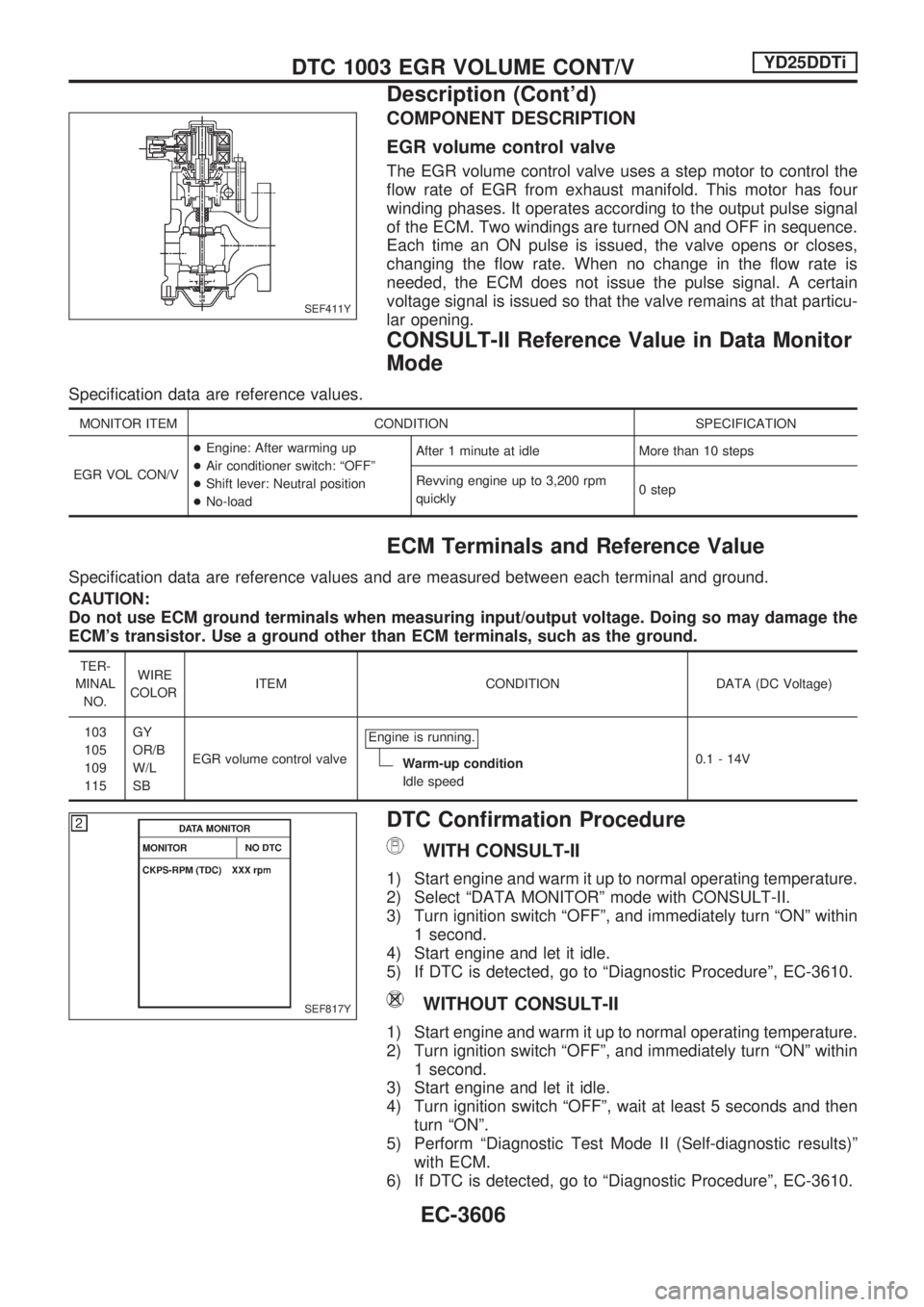
COMPONENT DESCRIPTION
EGR volume control valve
The EGR volume control valve uses a step motor to control the
flow rate of EGR from exhaust manifold. This motor has four
winding phases. It operates according to the output pulse signal
of the ECM. Two windings are turned ON and OFF in sequence.
Each time an ON pulse is issued, the valve opens or closes,
changing the flow rate. When no change in the flow rate is
needed, the ECM does not issue the pulse signal. A certain
voltage signal is issued so that the valve remains at that particu-
lar opening.
CONSULT-II Reference Value in Data Monitor
Mode
Specification data are reference values.
MONITOR ITEM CONDITION SPECIFICATION
EGR VOL CON/V+Engine: After warming up
+Air conditioner switch: ªOFFº
+Shift lever: Neutral position
+No-loadAfter 1 minute at idle More than 10 steps
Revving engine up to 3,200 rpm
quickly0 step
ECM Terminals and Reference Value
Specification data are reference values and are measured between each terminal and ground.
CAUTION:
Do not use ECM ground terminals when measuring input/output voltage. Doing so may damage the
ECM's transistor. Use a ground other than ECM terminals, such as the ground.
TER-
MINAL
NO.WIRE
COLORITEM CONDITION DATA (DC Voltage)
103
105
109
115GY
OR/B
W/L
SBEGR volume control valveEngine is running.
Warm-up condition
Idle speed0.1 - 14V
DTC Confirmation Procedure
WITH CONSULT-II
1) Start engine and warm it up to normal operating temperature.
2) Select ªDATA MONITORº mode with CONSULT-II.
3) Turn ignition switch ªOFFº, and immediately turn ªONº within
1 second.
4) Start engine and let it idle.
5) If DTC is detected, go to ªDiagnostic Procedureº, EC-3610.
WITHOUT CONSULT-II
1) Start engine and warm it up to normal operating temperature.
2) Turn ignition switch ªOFFº, and immediately turn ªONº within
1 second.
3) Start engine and let it idle.
4) Turn ignition switch ªOFFº, wait at least 5 seconds and then
turn ªONº.
5) Perform ªDiagnostic Test Mode II (Self-diagnostic results)º
with ECM.
6) If DTC is detected, go to ªDiagnostic Procedureº, EC-3610.
SEF411Y
SEF817Y
DTC 1003 EGR VOLUME CONT/VYD25DDTi
Description (Cont'd)
EC-3606
Page 637 of 1306
9 CHECK EGR VOLUME CONTROL VALVE-I
Check resistance between EGR volume control valve terminal 2 and terminals 1, 3, terminal 5 and terminals 4, 6.
SEF414Y
OK or NG
OK (With CONSULT-II)cGO TO 10.
OK (Without CONSULT-II)cGO TO 11.
NGcReplace EGR volume control valve.
10 CHECK EGR VOLUME CONTROL VALVE-II
With CONSULT-II
1. Remove EGR volume control valve.
2. Reconnect ECM harness connector and EGR volume control valve harness connector.
3. Turn ignition switch ªONº.
4. Perform ªEGR VOL CONT/Vº in ªACTIVE TESTº mode with CONSULT-II.
5. Check that EGR volume control valve shaft moves smoothly forward and backward according to the valve opening steps.
SEF819Y
OK or NG
OKcGO TO 12.
NGcReplace EGR volume control valve.
DTC 1003 EGR VOLUME CONT/VYD25DDTi
Diagnostic Procedure (Cont'd)
EC-3612
Page 641 of 1306
DTC Confirmation Procedure
WITH CONSULT-II
1) Turn ignition switch ªONº and wait at least 2 seconds.
2) Select ªDATA MONITORº mode with CONSULT-II.
3) Start engine and run it for at least 2 seconds at idle speed.
(If engine does not run, turn ignition switch to ªSTARTº for at
least 2 seconds.)
4) Turn ignition switch ªOFFº, wait at least 5 seconds and then
turn ªONº.
5) If DTC is detected, go to ªDiagnostic Procedureº, EC-3620.
WITHOUT CONSULT-II
1) Turn ignition switch ªONº and wait at least 2 seconds.
2) Start engine and run it for at least 2 seconds at idle speed.
(If engine does not run, turn ignition switch to ªSTARTº for at
least 2 seconds.)
3) Turn ignition switch ªOFFº, wait at least 5 seconds and then
turn ªONº.
4) Perform ªDiagnostic Test Mode II (Self-diagnostic results)º
with ECM.
5) If DTC is detected, go to ªDiagnostic Procedureº, EC-3620.
SEF817Y
DTC 1004 FUEL CUT SYSTEM1YD25DDTi
EC-3616
Page 649 of 1306
Diagnostic Procedure
1 INSPECTION START
Check fuel level, fuel supplying system, starter motor, etc.
OK or NG
OKcGO TO 2.
NGcCorrect.
2 CHECK INSTALLATION
Check that all glow plug connecting plate nuts are installed properly.
SEC250D
OK or NG
OK (With CONSULT-II)cGO TO 3.
OK (Without CONSULT-II)cGO TO 4.
NGcInstall properly.
3 CHECK GLOW INDICATOR LAMP OPERATION
With CONSULT-II
1. Turn ignition switch ªONº.
2. Select ªCOOLAN TEMP/Sº in ªDATA MONITORº mode with CONSULT-II.
3. Confirm that ªCOOLAN TEMP/Sº indicates below 75ÉC (167ÉF). If it indicates above 75ÉC (167ÉF), cool down engine.
SEF013Y
4. Turn ignition switch ªOFFº, wait at least 5 seconds and then turn ªONº.
5. Make sure that glow indicator lamp is turned ªONº for 1.5 seconds or more after turning ignition switch ªONº, and then turned
ªOFFº.
OK or NG
OKcGO TO 5.
NGcGO TO 6.
4 CHECK GLOW INDICATOR LAMP OPERATION
GLOW CONTROL SYSTEMYD25DDTi
EC-3624
Page 731 of 1306
System Description
UNIFIED CONTROL METER
+Speedometer, odo/trip meter, tachometer, fuel gauge and water temperature gauge are controlled totally
by control unit.
+Digital meter is adopted for odo/trip meter.*
*The record of the odo meter is kept even if the battery cable is disconnected. The record of the trip meter
is erased when the battery cable is disconnected.
+Odo/trip meter segment can be checked in diagnosis mode.
+Meter/gauge can be checked in diagnosis mode.
HOW TO CHANGE THE DISPLAY FOR ODO/TRIP METER
Note:
Turn ignition switch to the ªONº position to operate odo/trip meter.
SEL253V
METER AND GAUGES
EL-3056
Page 745 of 1306

Meter/Gauge Operation and Odo/Trip Meter
Segment Check in Diagnosis Mode
DIAGNOSIS FUNCTION
+Odo/trip meter segment can be checked in diagnosis mode.
+Meters/gauges can be checked in diagnosis mode.
HOW TO ALTERNATE DIAGNOSIS MODE
1. Turn ignition switch to ON and change odo/trip meter to
ªTRIP Aº or ªTRIP Bº.
2. Turn ignition switch to OFF.
3. Turn ignition switch to ON when pushing odo/trip meter
switch.
4. Confirm that trip meter indicates ª000.0º.
5. Push odo/trip meter switch more than three times within 5
seconds.
6. All odo/trip meter segments should be turned on.
NOTE: If some segments are not turned on, unified meter
control unit with odo/trip meter should be replaced.
At this point, the unified control meter is turned to diagnosis
mode.
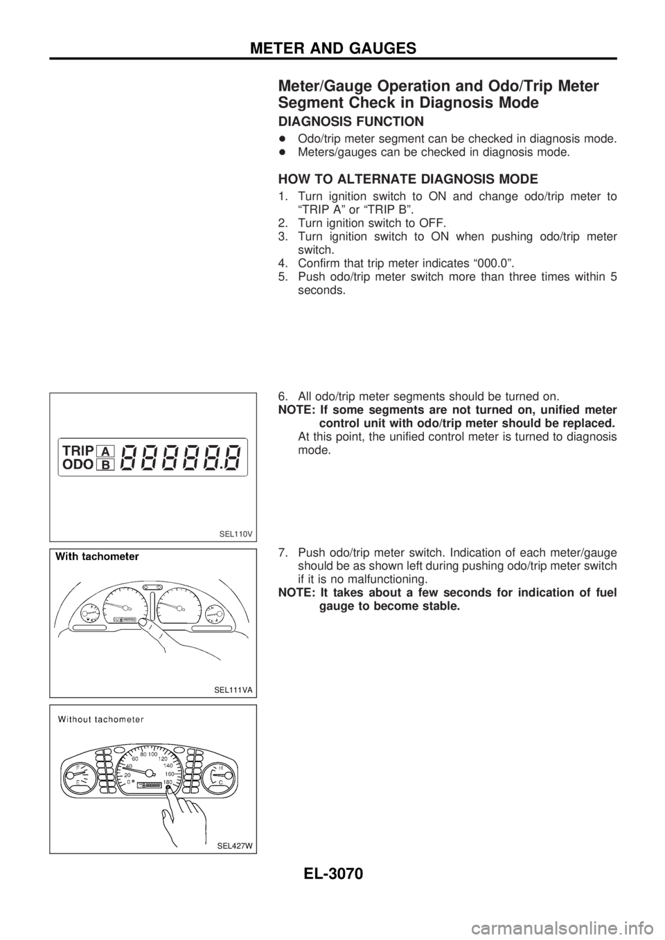
7. Push odo/trip meter switch. Indication of each meter/gauge
should be as shown left during pushing odo/trip meter switch
if it is no malfunctioning.
NOTE: It takes about a few seconds for indication of fuel
gauge to become stable.
SEL110V
SEL111VA
SEL427W
METER AND GAUGES
EL-3070
Page 814 of 1306

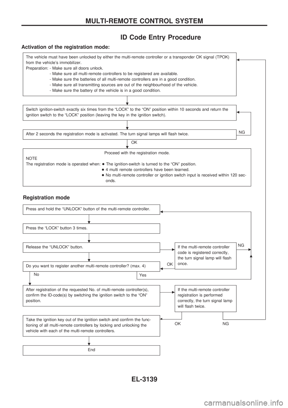
ID Code Entry Procedure
Activation of the registration mode:
The vehicle must have been unlocked by either the multi-remote controller or a transponder OK signal (TPOK)
from the vehicle's immobilizer.
Preparation: - Make sure all doors unlock.
- Make sure all multi-remote controllers to be registered are available.
- Make sure the batteries of all multi-remote controllers are in a good condition.
- Make sure all transmitting sources are out of the neighbourhood of the vehicle.
- Make sure the battery of the vehicle is in a good condition.b
Switch ignition-switch exactly six times from the ªLOCKº to the ªONº position within 10 seconds and return the
ignition switch to the ªLOCKº position (leaving the key in the ignition switch).b
After 2 seconds the registration mode is activated. The turn signal lamps will flash twice.
OKNG
Proceed with the registration mode.
NOTE
The registration mode is operated when:+The ignition-switch is turned to the ªONº position.
+4 multi remote controllers have been learned.
+No multi-remote controller or ignition switch input is received within 120 sec-
onds.
Registration mode
Press and hold the ªUNLOCKº button of the multi-remote controller.b
Press the ªLOCKº button 3 times.
Release the ªUNLOCKº button.cIf the multi-remote controller
code is registered correctly,
the turn signal lamp will flash
once.cNG
Do you want to register another multi-remote controller? (max. 4)
No
Yes
bOK
m
After registration of the requested No. of multi-remote controller(s),
confirm the ID-code(s) by switching the ignition switch to the ªONº
position.cIf the multi-remote controller
registration is performed
correctly, the turn signal lamp
will flash twice.
Take the ignition key out of the ignition switch and confirm the func-
tioning of all multi-remote controllers by locking and unlocking the
vehicle with each of the multi-remote controllers.b
OKNG
End
.
.
.
.
.
.
.
.
MULTI-REMOTE CONTROL SYSTEM
EL-3139
Page 823 of 1306

CONSULT-II DIAGNOSTIC TEST MODE FUNCTION
CONSULT-II DIAGNOSTIC TEST
MODEDescription
C/U INITIALIZATION When replacing any of the following components, C/U initialization is necessary.
[NATS ignition key/IMMU/ECM/Dongle unit]
SELF-DIAG RESULTS Detected items (screen terms) are as shown in the chart below.
NOTE:
When any initialization is performed, all ID previously registered will be erased. So all NATS ignition
keys must be registered again.
The engine cannot be started with an unregistered key. In this case, the system may show ªDIFFER-
ENCE OF KEYº or ªLOCK MODEº as a self-diagnostic result on the CONSULT-II screen.
When initialization is performed (for RHD models), security indicator will flash six times to demon-
strate recognition of dongle unit ID.
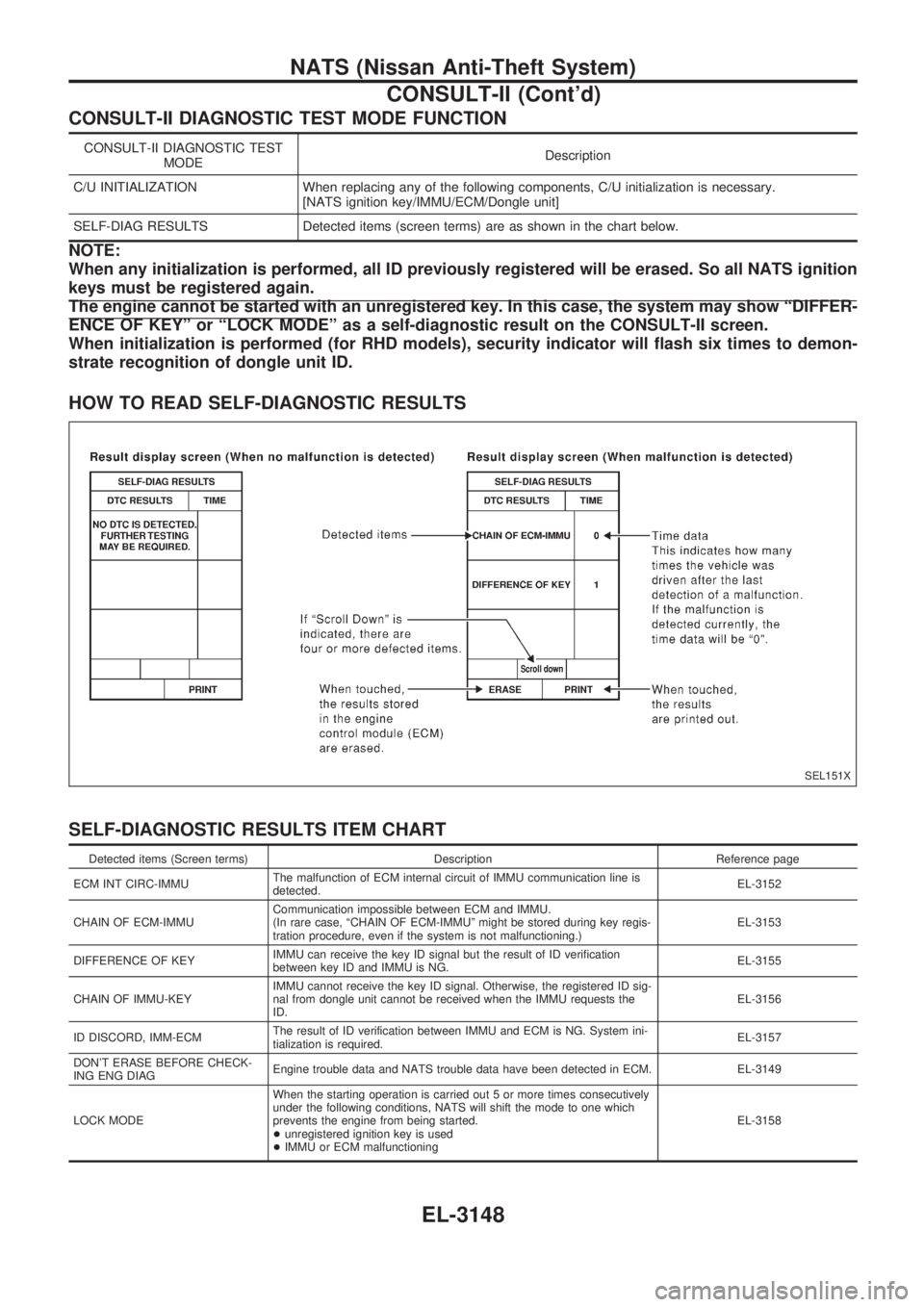
HOW TO READ SELF-DIAGNOSTIC RESULTS
SELF-DIAGNOSTIC RESULTS ITEM CHART
Detected items (Screen terms) Description Reference page
ECM INT CIRC-IMMUThe malfunction of ECM internal circuit of IMMU communication line is
detected.EL-3152
CHAIN OF ECM-IMMUCommunication impossible between ECM and IMMU.
(In rare case, ªCHAIN OF ECM-IMMUº might be stored during key regis-
tration procedure, even if the system is not malfunctioning.)EL-3153
DIFFERENCE OF KEYIMMU can receive the key ID signal but the result of ID verification
between key ID and IMMU is NG.EL-3155
CHAIN OF IMMU-KEYIMMU cannot receive the key ID signal. Otherwise, the registered ID sig-
nal from dongle unit cannot be received when the IMMU requests the
ID.EL-3156
ID DISCORD, IMM-ECMThe result of ID verification between IMMU and ECM is NG. System ini-
tialization is required.EL-3157
DON'T ERASE BEFORE CHECK-
ING ENG DIAGEngine trouble data and NATS trouble data have been detected in ECM. EL-3149
LOCK MODEWhen the starting operation is carried out 5 or more times consecutively
under the following conditions, NATS will shift the mode to one which
prevents the engine from being started.
+unregistered ignition key is used
+IMMU or ECM malfunctioningEL-3158
SEL151X
NATS (Nissan Anti-Theft System)
CONSULT-II (Cont'd)
EL-3148