Page 463 of 1306

REAL TIME DIAGNOSIS IN DATA MONITOR MODE
CONSULT-II has two kinds of triggers and they can be selected
by touching ªSETTINGº in ªDATA MONITORº mode.
1) ªAUTO TRIGº (Automatic trigger):
+The malfunction will be identified on the CONSULT-II screen
in real time.
In other words, DTC will be displayed if the malfunction is
detected by ECM.
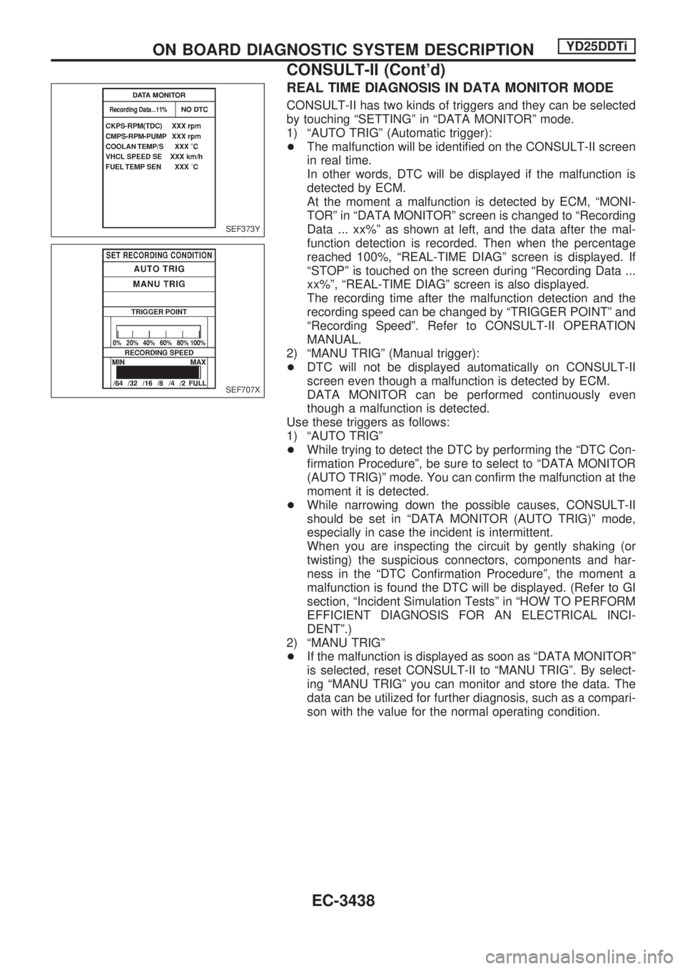
At the moment a malfunction is detected by ECM, ªMONI-
TORº in ªDATA MONITORº screen is changed to ªRecording
Data ... xx%º as shown at left, and the data after the mal-
function detection is recorded. Then when the percentage
reached 100%, ªREAL-TIME DIAGº screen is displayed. If
ªSTOPº is touched on the screen during ªRecording Data ...
xx%º, ªREAL-TIME DIAGº screen is also displayed.
The recording time after the malfunction detection and the
recording speed can be changed by ªTRIGGER POINTº and
ªRecording Speedº. Refer to CONSULT-II OPERATION
MANUAL.
2) ªMANU TRIGº (Manual trigger):
+DTC will not be displayed automatically on CONSULT-II
screen even though a malfunction is detected by ECM.
DATA MONITOR can be performed continuously even
though a malfunction is detected.
Use these triggers as follows:
1) ªAUTO TRIGº
+While trying to detect the DTC by performing the ªDTC Con-
firmation Procedureº, be sure to select to ªDATA MONITOR
(AUTO TRIG)º mode. You can confirm the malfunction at the
moment it is detected.
+While narrowing down the possible causes, CONSULT-II
should be set in ªDATA MONITOR (AUTO TRIG)º mode,
especially in case the incident is intermittent.
When you are inspecting the circuit by gently shaking (or
twisting) the suspicious connectors, components and har-
ness in the ªDTC Confirmation Procedureº, the moment a
malfunction is found the DTC will be displayed. (Refer to GI
section, ªIncident Simulation Testsº in ªHOW TO PERFORM
EFFICIENT DIAGNOSIS FOR AN ELECTRICAL INCI-
DENTº.)
2) ªMANU TRIGº
+If the malfunction is displayed as soon as ªDATA MONITORº
is selected, reset CONSULT-II to ªMANU TRIGº. By select-
ing ªMANU TRIGº you can monitor and store the data. The
data can be utilized for further diagnosis, such as a compari-
son with the value for the normal operating condition.
SEF373Y
SEF707X
ON BOARD DIAGNOSTIC SYSTEM DESCRIPTIONYD25DDTi
CONSULT-II (Cont'd)
EC-3438
Page 505 of 1306

Description
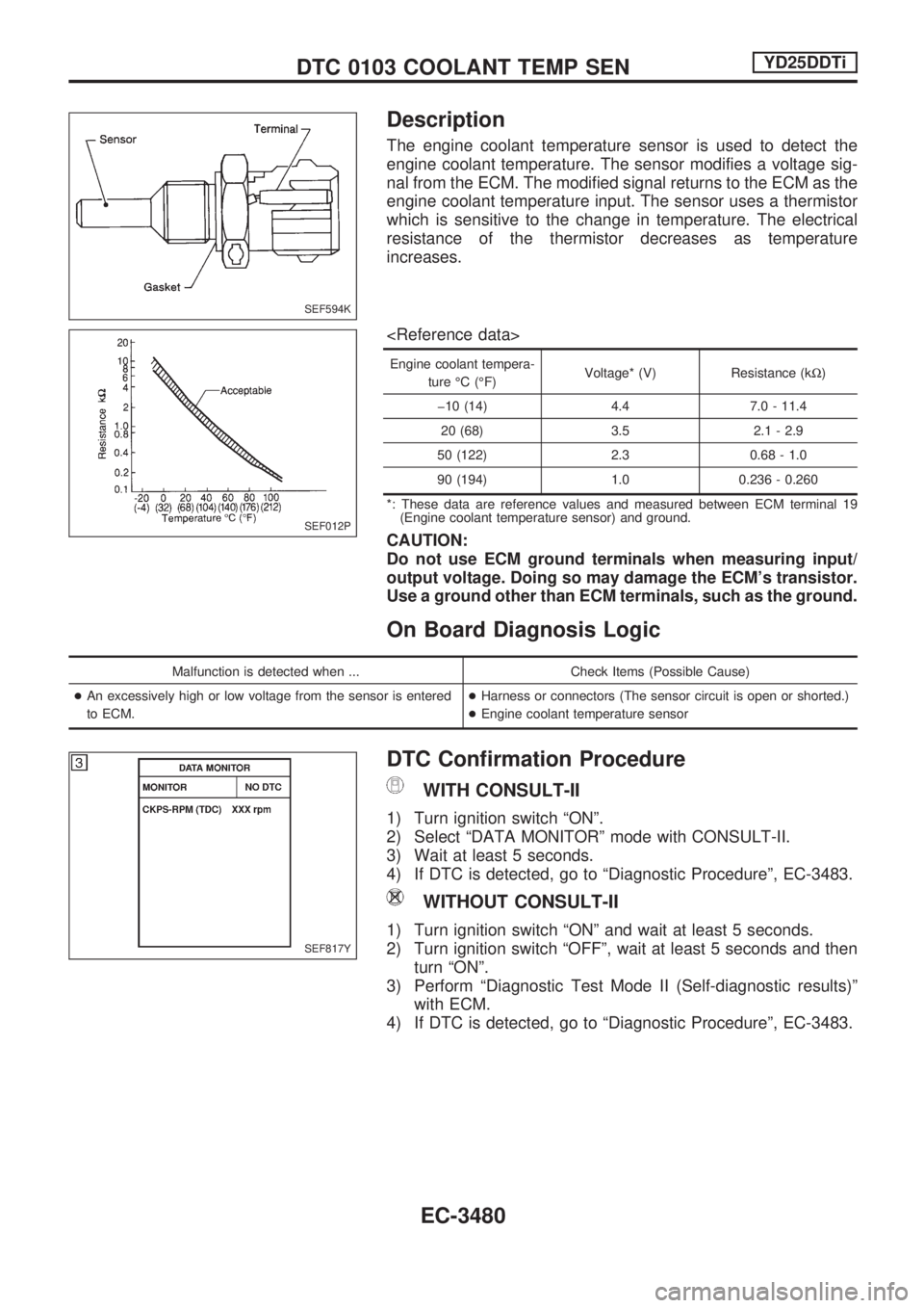
The engine coolant temperature sensor is used to detect the
engine coolant temperature. The sensor modifies a voltage sig-
nal from the ECM. The modified signal returns to the ECM as the
engine coolant temperature input. The sensor uses a thermistor
which is sensitive to the change in temperature. The electrical
resistance of the thermistor decreases as temperature
increases.
Engine coolant tempera-
ture ÉC (ÉF)Voltage* (V) Resistance (kW)
þ10 (14) 4.4 7.0 - 11.4
20 (68) 3.5 2.1 - 2.9
50 (122) 2.3 0.68 - 1.0
90 (194) 1.0 0.236 - 0.260
*: These data are reference values and measured between ECM terminal 19
(Engine coolant temperature sensor) and ground.
CAUTION:
Do not use ECM ground terminals when measuring input/
output voltage. Doing so may damage the ECM's transistor.
Use a ground other than ECM terminals, such as the ground.
On Board Diagnosis Logic
Malfunction is detected when ... Check Items (Possible Cause)
+An excessively high or low voltage from the sensor is entered
to ECM.+Harness or connectors (The sensor circuit is open or shorted.)
+Engine coolant temperature sensor
DTC Confirmation Procedure
WITH CONSULT-II
1) Turn ignition switch ªONº.
2) Select ªDATA MONITORº mode with CONSULT-II.
3) Wait at least 5 seconds.
4) If DTC is detected, go to ªDiagnostic Procedureº, EC-3483.
WITHOUT CONSULT-II
1) Turn ignition switch ªONº and wait at least 5 seconds.
2) Turn ignition switch ªOFFº, wait at least 5 seconds and then
turn ªONº.
3) Perform ªDiagnostic Test Mode II (Self-diagnostic results)º
with ECM.
4) If DTC is detected, go to ªDiagnostic Procedureº, EC-3483.
SEF594K
SEF012P
SEF817Y
DTC 0103 COOLANT TEMP SENYD25DDTi
EC-3480
Page 526 of 1306
Description
The ECM consists of a microcomputer and connectors for signal
input and output and for power supply. The unit controls the
engine.
On Board Diagnosis Logic
Malfunction is detected when ... Check Items (Possible Cause)
+ECM calculation function is malfunctioning.+ECM
(ECCS-D control module)
DTC Confirmation Procedure
WITH CONSULT-II
1) Turn ignition switch ªONº.
2) Select ªDATA MONITORº mode with CONSULT-II.
3) Start engine and wait at least 2 seconds.
4) If DTC is detected, go to ªDiagnostic Procedureº, EC-3503.
WITHOUT CONSULT-II
1) Turn ignition switch ªONº and wait at least 2 seconds.
2) Start engine and wait at least 2 seconds.
3) Turn ignition switch ªOFFº, wait at least 5 seconds and then
turn ªONº.
4) Perform ªDiagnostic Test Mode II (Self-diagnostic results)º
with ECM.
5) If DTC is detected, go to ªDiagnostic Procedureº, EC-3503.
SEC220B
SEF817Y
DTC 0301 ECM 2, DTC 901 ECM 12YD25DDTi
EC-3501
Page 528 of 1306

Component Description
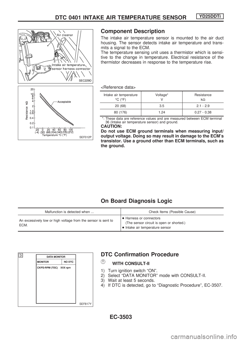
The intake air temperature sensor is mounted to the air duct
housing. The sensor detects intake air temperature and trans-
mits a signal to the ECM.
The temperature sensing unit uses a thermistor which is sensi-
tive to the change in temperature. Electrical resistance of the
thermistor decreases in response to the temperature rise.
Intake air temperature
ÉC (ÉF)Voltage*
VResistance
kW
20 (68) 3.5 2.1 - 2.9
80 (176) 1.24 0.27 - 0.38
*: These data are reference values and are measured between ECM terminal
36 (Intake air temperature sensor) and ground.
CAUTION:
Do not use ECM ground terminals when measuring input/
output voltage. Doing so may result in damage to the ECM's
transistor. Use a ground other than ECM terminals, such as
the ground.
On Board Diagnosis Logic
Malfunction is detected when ... Check Items (Possible Cause)
An excessively low or high voltage from the sensor is sent to
ECM.+Harness or connectors
(The sensor circuit is open or shorted.)
+Intake air temperature sensor
DTC Confirmation Procedure
WITH CONSULT-II
1) Turn ignition switch ªONº.
2) Select ªDATA MONITORº mode with CONSULT-II.
3) Wait at least 5 seconds.
4) If DTC is detected, go to ªDiagnostic Procedureº, EC-3507.
SEC229D
SEF012P
SEF817Y
DTC 0401 INTAKE AIR TEMPERATURE SENSORYD25DDTi
EC-3503
Page 529 of 1306
WITHOUT CONSULT-II
WITHOUT CONSULT-II
1. Turn ignition switch ªONº and wait at least 5 seconds.
2. Turn ignition switch ªOFFº, wait at least 5 seconds and then
turn ªONº.
3. Perform ªDiagnostic Test Mode II (Self-diagnostic results)º
with ECM.
4. If DTC is detected, go to EC-3507.
DTC 0401 INTAKE AIR TEMPERATURE SENSORYD25DDTi
DTC Confirmation Procedure (Cont'd)
EC-3504
Page 535 of 1306

On Board Diagnosis Logic
Malfunction is detected when .... Check Items (Possible cause)
+An improper voltage signal from fuel temperature sensor
(Built-into electronic control fuel injection pump) is sent to
injection pump control unit.+Harness or connectors
(Electronic control fuel injection pump circuit is open or
shorted.)
+Electronic control fuel injection pump
DTC Confirmation Procedure
WITH CONSULT-II
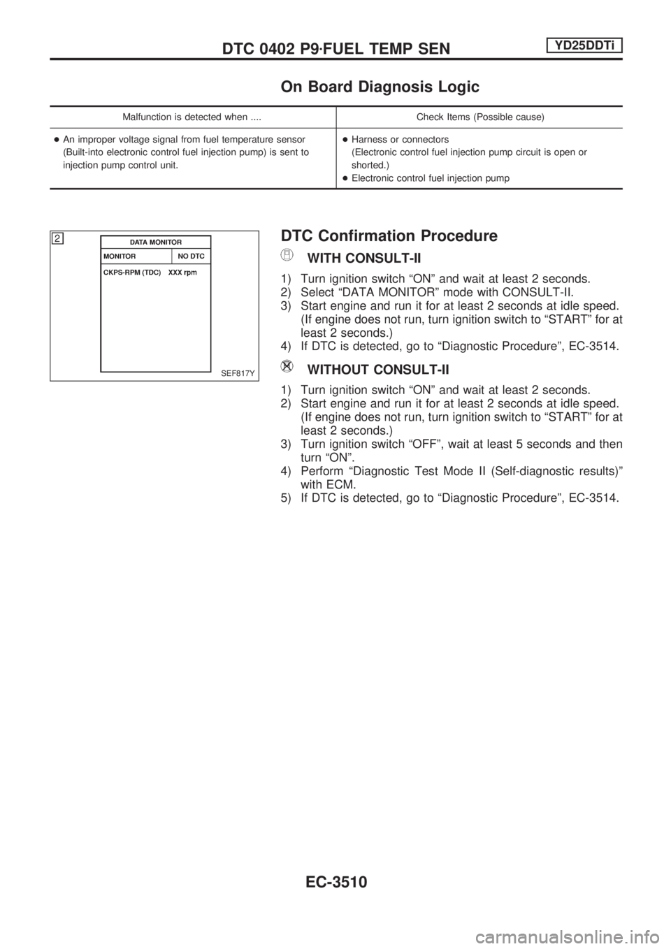
1) Turn ignition switch ªONº and wait at least 2 seconds.
2) Select ªDATA MONITORº mode with CONSULT-II.
3) Start engine and run it for at least 2 seconds at idle speed.
(If engine does not run, turn ignition switch to ªSTARTº for at
least 2 seconds.)
4) If DTC is detected, go to ªDiagnostic Procedureº, EC-3514.
WITHOUT CONSULT-II
1) Turn ignition switch ªONº and wait at least 2 seconds.
2) Start engine and run it for at least 2 seconds at idle speed.
(If engine does not run, turn ignition switch to ªSTARTº for at
least 2 seconds.)
3) Turn ignition switch ªOFFº, wait at least 5 seconds and then
turn ªONº.
4) Perform ªDiagnostic Test Mode II (Self-diagnostic results)º
with ECM.
5) If DTC is detected, go to ªDiagnostic Procedureº, EC-3514.
SEF817Y
DTC 0402 P9zFUEL TEMP SENYD25DDTi
EC-3510
Page 542 of 1306
DTC Confirmation Procedure
WITH CONSULT-II
1) Turn ignition switch ªONº.
2) Select ªDATA MONITORº mode with CONSULT-II.
3) Depress and release fully accelerator pedal slowly.
4) If DTC is detected, go to ªDiagnostic Procedureº, EC-3523.
WITHOUT CONSULT-II
1) Turn ignition switch ªONº.
2) Depress and release fully accelerator pedal slowly.
3) Turn ignition switch ªOFFº, wait at least 5 seconds and then
turn ªONº.
4) Perform ªDiagnostic Test Mode II (Self-diagnostic results)º
with ECM.
5) If DTC is detected, go to ªDiagnostic Procedureº, EC-3523.SEF817Y
DTC 0403 ACCEL POS SENSORYD25DDTi
EC-3517
Page 551 of 1306
9 CHECK ACCELERATOR POSITION SENSOR
With CONSULT-II
1. Reconnect all disconnected harness connectors.
2. Turn ignition switch ªONº.
3. Select ªDATA MONITORº mode with CONSULT-II.
4. Check the indication of ªACCEL POS SENº under the following conditions.
SEF818YB
OK or NG
OK (LHD models)cGO TO 13.
OK (RHD models)cGO TO 11.
NGcReplace accelerator pedal assembly.
10 CHECK ACCELERATOR POSITION SENSOR
Without CONSULT-II
1. Reconnect all disconnected harness connectors.
2. Turn ignition switch ªONº.
3. Check voltage between ECM terminal 23 and ground under the following conditions.
SEF407YB
OK or NG
OK (LHD models)cGO TO 14.
OK (RHD models)cGO TO 11.
NGcReplace accelerator pedal assembly.
DTC 0403 ACCEL POS SENSORYD25DDTi
Diagnostic Procedure (Cont'd)
EC-3526