2001 NISSAN PICK-UP check engine
[x] Cancel search: check enginePage 1036 of 1306
![NISSAN PICK-UP 2001 Repair Manual REMOVAL
1. Place a pan to catch the oil under the lower part of drain hose
outlet before removing filter body.
2. Using a hexagonal socket wrench [plane-to-plane width: 24
mm (0.94 in)], loosen the fi NISSAN PICK-UP 2001 Repair Manual REMOVAL
1. Place a pan to catch the oil under the lower part of drain hose
outlet before removing filter body.
2. Using a hexagonal socket wrench [plane-to-plane width: 24
mm (0.94 in)], loosen the fi](/manual-img/5/57372/w960_57372-1035.png)
REMOVAL
1. Place a pan to catch the oil under the lower part of drain hose
outlet before removing filter body.
2. Using a hexagonal socket wrench [plane-to-plane width: 24
mm (0.94 in)], loosen the filter body approximately four turns.
3. Remove the filter body, then remove the oil filter element.
4. Remove the O-ring from the filter body.
+Push the O-ring in one direction, lift the slack part using
fingers, and remove the O-ring from the filter body.
CAUTION:
Do not use wires or flat-bladed screwdrivers etc. as they
may cause damage to the filter body.
INSTALLATION
1. Completely remove all foreign objects adhering to the inside
of the filter body or O-ring mounting area (filter body side and
bracket side).
2. Install the oil filter element and O-ring to the filter body.
+Push the oil filter element into the filter body completely.
3. Install the filter body to the oil filter bracket.
:20-25Nzm (2.0 - 2.6 kg-m, 15 - 18 ft-lb)
4. After warming up the engine, check for engine oil leakage
and oil level.
CAUTION:
Completely wipe clean any engine oil remaining on the fil-
ter body or vehicle.
Changing Engine Coolant
To avoid the danger of being scalded, never change the
coolant when the engine is hot.
Ð DRAINING ENGINE COOLANT Ð
1. Set air conditioning system as follows to prevent coolant from
remaining in the system.
a. Turn ignition switch ON and set temperature controller to
maximum hot position.
b. Wait 10 seconds before turning ignition switch OFF.
2. Open radiator drain plug at the bottom of radiator and
remove radiator cap to drain coolant.
SMA160D
JLC292B OK
SMA161D
ENGINE MAINTENANCEYD25DDTi
Changing Oil Filter (Cont'd)
MA-3014
Page 1037 of 1306
3. Remove reservoir tank, drain coolant, then clean reservoir
tank.
+Be careful not to allow coolant to contact drive belts.
4. Remove drain plug of cylinder block.
5. Check drained coolant for contaminants such as rust, corro-
sion or discoloration. If contaminated flush engine cooling
system, refer to MA-3016, ªFLUSHING COOLING SYS-
TEMº.
Ð REFILLING ENGINE COOLANT Ð
1. Install reservoir tank, radiator drain plug and cylinder block
drain plug.
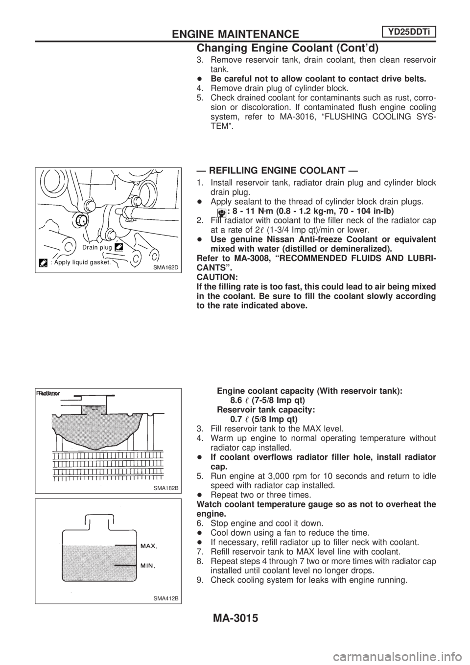
+Apply sealant to the thread of cylinder block drain plugs.
:8-11Nzm (0.8 - 1.2 kg-m, 70 - 104 in-lb)
2. Fill radiator with coolant to the filler neck of the radiator cap
at a rate of 2!(1-3/4 Imp qt)/min or lower.
+Use genuine Nissan Anti-freeze Coolant or equivalent
mixed with water (distilled or demineralized).
Refer to MA-3008, ªRECOMMENDED FLUIDS AND LUBRI-
CANTSº.
CAUTION:
If the filling rate is too fast, this could lead to air being mixed
in the coolant. Be sure to fill the coolant slowly according
to the rate indicated above.
Engine coolant capacity (With reservoir tank):
8.6!(7-5/8 Imp qt)
Reservoir tank capacity:
0.7!(5/8 Imp qt)
3. Fill reservoir tank to the MAX level.
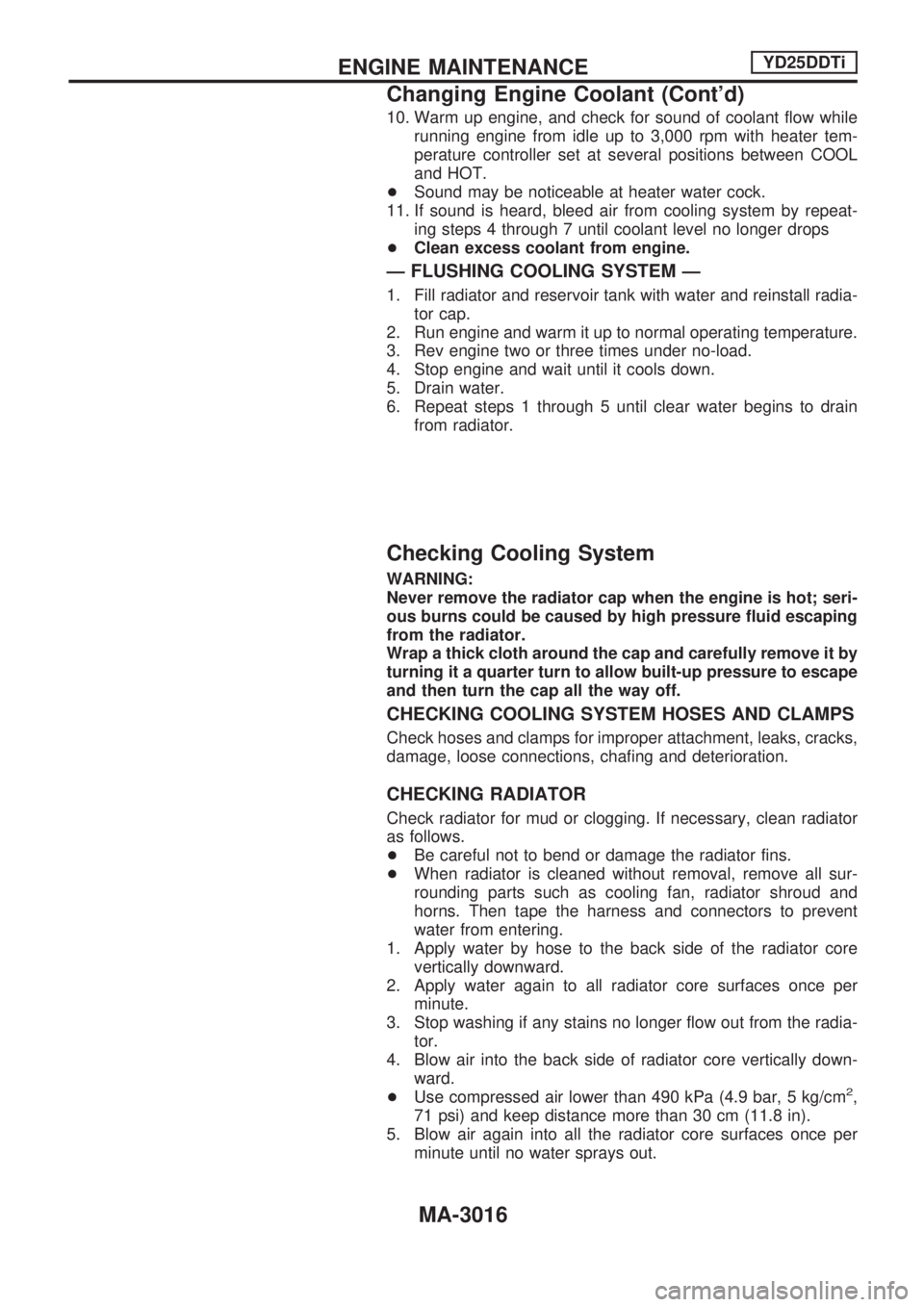
4. Warm up engine to normal operating temperature without
radiator cap installed.
+If coolant overflows radiator filler hole, install radiator
cap.
5. Run engine at 3,000 rpm for 10 seconds and return to idle
speed with radiator cap installed.
+Repeat two or three times.
Watch coolant temperature gauge so as not to overheat the
engine.
6. Stop engine and cool it down.
+Cool down using a fan to reduce the time.
+If necessary, refill radiator up to filler neck with coolant.
7. Refill reservoir tank to MAX level line with coolant.
8. Repeat steps 4 through 7 two or more times with radiator cap
installed until coolant level no longer drops.
9. Check cooling system for leaks with engine running.
SMA162D
SMA182B Radiator
SMA412B
ENGINE MAINTENANCEYD25DDTi
Changing Engine Coolant (Cont'd)
MA-3015
Page 1038 of 1306
10. Warm up engine, and check for sound of coolant flow while
running engine from idle up to 3,000 rpm with heater tem-
perature controller set at several positions between COOL
and HOT.
+Sound may be noticeable at heater water cock.
11. If sound is heard, bleed air from cooling system by repeat-
ing steps 4 through 7 until coolant level no longer drops
+Clean excess coolant from engine.
Ð FLUSHING COOLING SYSTEM Ð
1. Fill radiator and reservoir tank with water and reinstall radia-
tor cap.
2. Run engine and warm it up to normal operating temperature.
3. Rev engine two or three times under no-load.
4. Stop engine and wait until it cools down.
5. Drain water.
6. Repeat steps 1 through 5 until clear water begins to drain
from radiator.
Checking Cooling System
WARNING:
Never remove the radiator cap when the engine is hot; seri-
ous burns could be caused by high pressure fluid escaping
from the radiator.
Wrap a thick cloth around the cap and carefully remove it by
turning it a quarter turn to allow built-up pressure to escape
and then turn the cap all the way off.
CHECKING COOLING SYSTEM HOSES AND CLAMPS
Check hoses and clamps for improper attachment, leaks, cracks,
damage, loose connections, chafing and deterioration.
CHECKING RADIATOR
Check radiator for mud or clogging. If necessary, clean radiator
as follows.
+Be careful not to bend or damage the radiator fins.
+When radiator is cleaned without removal, remove all sur-
rounding parts such as cooling fan, radiator shroud and
horns. Then tape the harness and connectors to prevent
water from entering.
1. Apply water by hose to the back side of the radiator core
vertically downward.
2. Apply water again to all radiator core surfaces once per
minute.
3. Stop washing if any stains no longer flow out from the radia-
tor.
4. Blow air into the back side of radiator core vertically down-
ward.
+Use compressed air lower than 490 kPa (4.9 bar, 5 kg/cm
2,
71 psi) and keep distance more than 30 cm (11.8 in).
5. Blow air again into all the radiator core surfaces once per
minute until no water sprays out.
ENGINE MAINTENANCEYD25DDTi
Changing Engine Coolant (Cont'd)
MA-3016
Page 1039 of 1306
CHECKING RADIATOR CAP
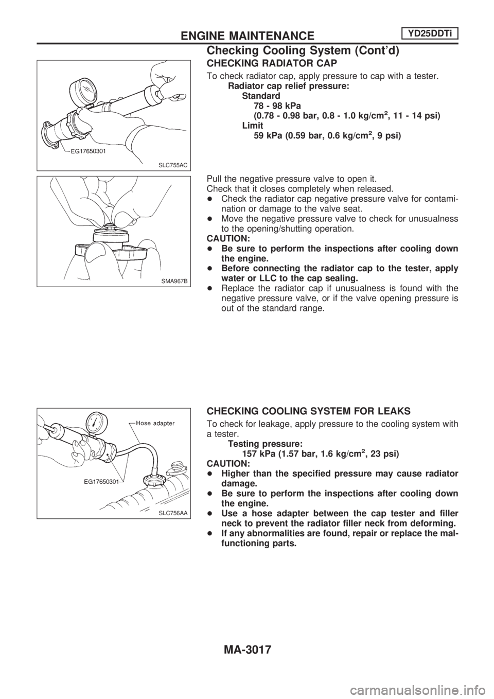
To check radiator cap, apply pressure to cap with a tester.
Radiator cap relief pressure:
Standard
78-98kPa
(0.78 - 0.98 bar, 0.8 - 1.0 kg/cm
2, 11 - 14 psi)
Limit
59 kPa (0.59 bar, 0.6 kg/cm
2, 9 psi)
Pull the negative pressure valve to open it.
Check that it closes completely when released.
+Check the radiator cap negative pressure valve for contami-
nation or damage to the valve seat.
+Move the negative pressure valve to check for unusualness
to the opening/shutting operation.
CAUTION:
+Be sure to perform the inspections after cooling down
the engine.
+Before connecting the radiator cap to the tester, apply
water or LLC to the cap sealing.
+Replace the radiator cap if unusualness is found with the
negative pressure valve, or if the valve opening pressure is
out of the standard range.
CHECKING COOLING SYSTEM FOR LEAKS
To check for leakage, apply pressure to the cooling system with
a tester.
Testing pressure:
157 kPa (1.57 bar, 1.6 kg/cm
2, 23 psi)
CAUTION:
+Higher than the specified pressure may cause radiator
damage.
+Be sure to perform the inspections after cooling down
the engine.
+Use a hose adapter between the cap tester and filler
neck to prevent the radiator filler neck from deforming.
+If any abnormalities are found, repair or replace the mal-
functioning parts.
SLC755AC
SMA967B
SLC756AA
ENGINE MAINTENANCEYD25DDTi
Checking Cooling System (Cont'd)
MA-3017
Page 1040 of 1306
Checking and Replacing Fuel Filter and
Draining Water
Be careful not to spill fuel in engine compartment. Place a
rag to absorb fuel.
CHECKING FUEL FILTER
Check fuel filter for fuel leakage, damage and other abnormal
signs.
REPLACING FUEL FILTER
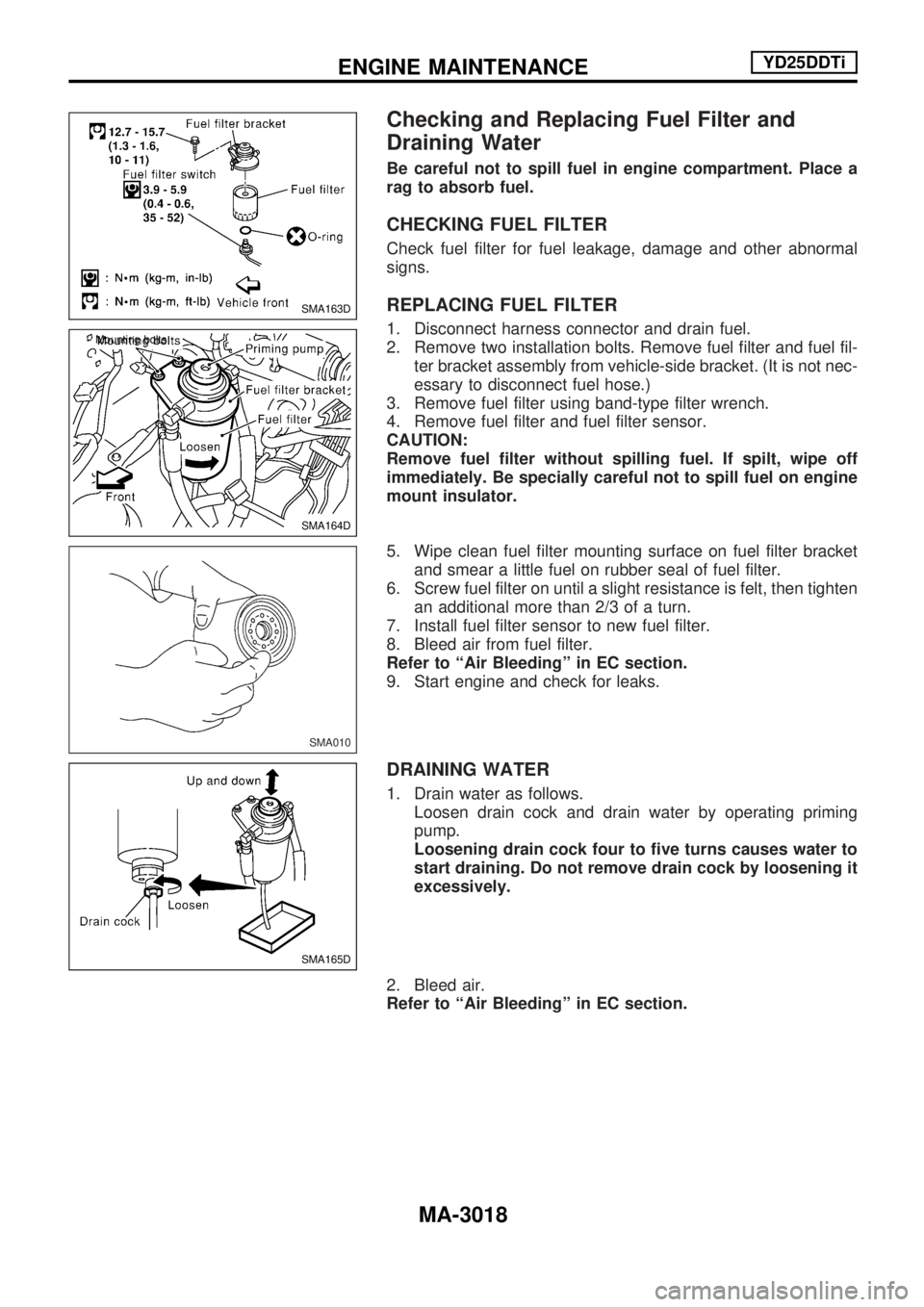
1. Disconnect harness connector and drain fuel.
2. Remove two installation bolts. Remove fuel filter and fuel fil-
ter bracket assembly from vehicle-side bracket. (It is not nec-
essary to disconnect fuel hose.)
3. Remove fuel filter using band-type filter wrench.
4. Remove fuel filter and fuel filter sensor.
CAUTION:
Remove fuel filter without spilling fuel. If spilt, wipe off
immediately. Be specially careful not to spill fuel on engine
mount insulator.
5. Wipe clean fuel filter mounting surface on fuel filter bracket
and smear a little fuel on rubber seal of fuel filter.
6. Screw fuel filter on until a slight resistance is felt, then tighten
an additional more than 2/3 of a turn.
7. Install fuel filter sensor to new fuel filter.
8. Bleed air from fuel filter.
Refer to ªAir Bleedingº in EC section.
9. Start engine and check for leaks.
DRAINING WATER
1. Drain water as follows.
Loosen drain cock and drain water by operating priming
pump.
Loosening drain cock four to five turns causes water to
start draining. Do not remove drain cock by loosening it
excessively.
2. Bleed air.
Refer to ªAir Bleedingº in EC section.
SMA163D
SMA164D Mounting bolts
SMA010
SMA165D
ENGINE MAINTENANCEYD25DDTi
MA-3018
Page 1041 of 1306
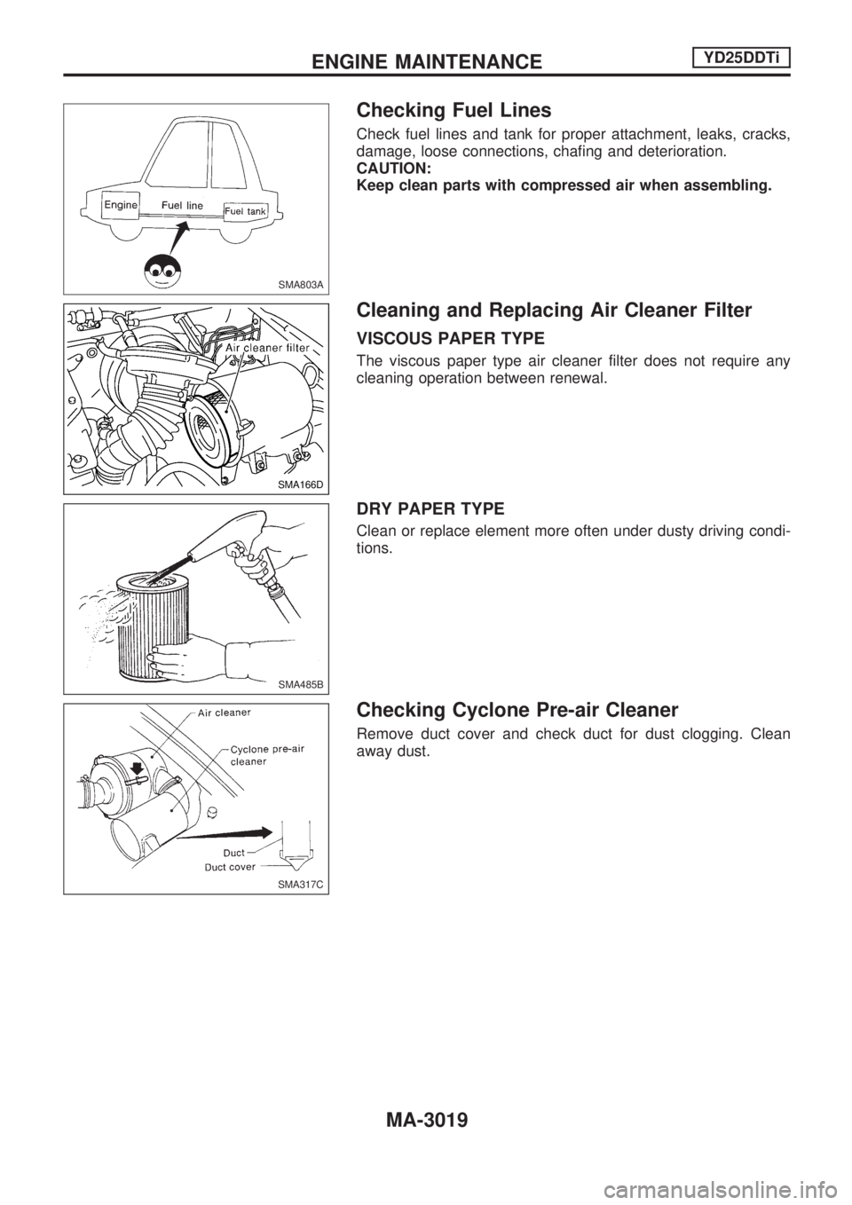
Checking Fuel Lines
Check fuel lines and tank for proper attachment, leaks, cracks,
damage, loose connections, chafing and deterioration.
CAUTION:
Keep clean parts with compressed air when assembling.
Cleaning and Replacing Air Cleaner Filter
VISCOUS PAPER TYPE
The viscous paper type air cleaner filter does not require any
cleaning operation between renewal.
DRY PAPER TYPE
Clean or replace element more often under dusty driving condi-
tions.
Checking Cyclone Pre-air Cleaner
Remove duct cover and check duct for dust clogging. Clean
away dust.
SMA803A
SMA166D
SMA485B
SMA317C
ENGINE MAINTENANCEYD25DDTi
MA-3019
Page 1042 of 1306
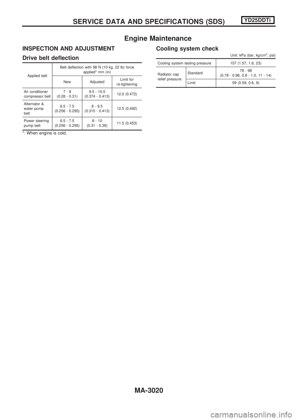
Engine Maintenance
INSPECTION AND ADJUSTMENT
Drive belt deflection
Applied beltBelt deflection with 98 N (10 kg, 22 lb) force
applied* mm (in)
New Adjusted Limit for
re-tightening
Air conditioner
compressor belt 7-8
(0.28 - 0.31) 9.5 - 10.5
(0.374 - 0.413) 12.0 (0.472)
Alternator &
water pump
belt 6.5 - 7.5
(0.256 - 0.295) 8 - 9.5
(0.315 - 0.413) 12.5 (0.492)
Power steering
pump belt 6.5 - 7.5
(0.256 - 0.295) 8-10
(0.31 - 0.39) 11.5 (0.453)
*: When engine is cold.
Cooling system check
Unit: kPa (bar, kg/cm2, psi)
Cooling system testing pressure 157 (1.57, 1.6, 23)
Radiator cap
relief pressureStandard
78-98
(0.78 - 0.98, 0.8 - 1.0, 11 - 14)
Limit 59 (0.59, 0.6, 9)
SERVICEDATAANDSPECIFICATIONS(SDS) YD25DDTi
MA-3020
Page 1043 of 1306
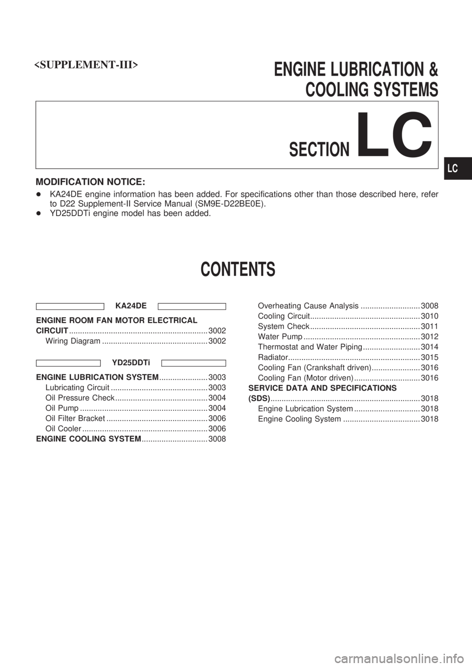
ENGINE LUBRICATION &
COOLING SYSTEMS
SECTION
LC
MODIFICATION NOTICE:
+KA24DE engine information has been added. For specifications other than those described here, refer
to D22 Supplement-II Service Manual (SM9E-D22BE0E).
+YD25DDTi engine model has been added.
CONTENTS
KA24DE
ENGINE ROOM FAN MOTOR ELECTRICAL
CIRCUIT............................................................... 3002
Wiring Diagram ................................................ 3002
YD25DDTi
ENGINE LUBRICATION SYSTEM...................... 3003
Lubricating Circuit ............................................ 3003
Oil Pressure Check .......................................... 3004
Oil Pump .......................................................... 3004
Oil Filter Bracket .............................................. 3006
Oil Cooler ......................................................... 3006
ENGINE COOLING SYSTEM.............................. 3008Overheating Cause Analysis ........................... 3008
Cooling Circuit.................................................. 3010
System Check .................................................. 3011
Water Pump ..................................................... 3012
Thermostat and Water Piping .......................... 3014
Radiator............................................................ 3015
Cooling Fan (Crankshaft driven)...................... 3016
Cooling Fan (Motor driven) .............................. 3016
SERVICE DATA AND SPECIFICATIONS
(SDS).................................................................... 3018
Engine Lubrication System .............................. 3018
Engine Cooling System ................................... 3018
LC