2001 NISSAN PICK-UP check engine
[x] Cancel search: check enginePage 942 of 1306
Removal operation
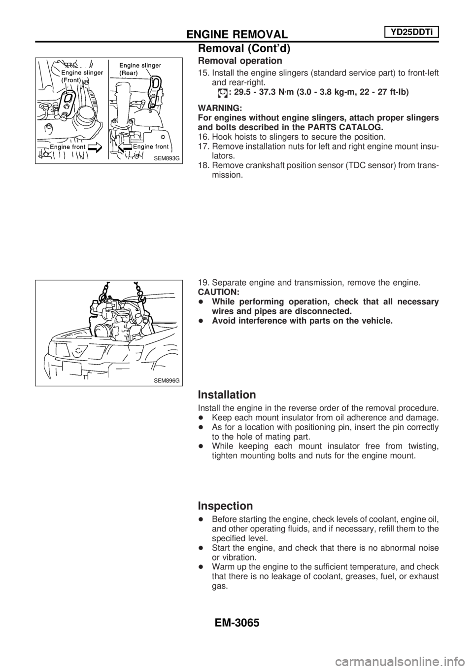
15. Install the engine slingers (standard service part) to front-left
and rear-right.
: 29.5 - 37.3 Nzm (3.0 - 3.8 kg-m, 22 - 27 ft-lb)
WARNING:
For engines without engine slingers, attach proper slingers
and bolts described in the PARTS CATALOG.
16. Hook hoists to slingers to secure the position.
17. Remove installation nuts for left and right engine mount insu-
lators.
18. Remove crankshaft position sensor (TDC sensor) from trans-
mission.
19. Separate engine and transmission, remove the engine.
CAUTION:
+While performing operation, check that all necessary
wires and pipes are disconnected.
+Avoid interference with parts on the vehicle.
Installation
Install the engine in the reverse order of the removal procedure.
+Keep each mount insulator from oil adherence and damage.
+As for a location with positioning pin, insert the pin correctly
to the hole of mating part.
+While keeping each mount insulator free from twisting,
tighten mounting bolts and nuts for the engine mount.
Inspection
+Before starting the engine, check levels of coolant, engine oil,
and other operating fluids, and if necessary, refill them to the
specified level.
+Start the engine, and check that there is no abnormal noise
or vibration.
+Warm up the engine to the sufficient temperature, and check
that there is no leakage of coolant, greases, fuel, or exhaust
gas.
SEM893G
SEM896G
ENGINE REMOVALYD25DDTi
Removal (Cont'd)
EM-3065
Page 945 of 1306
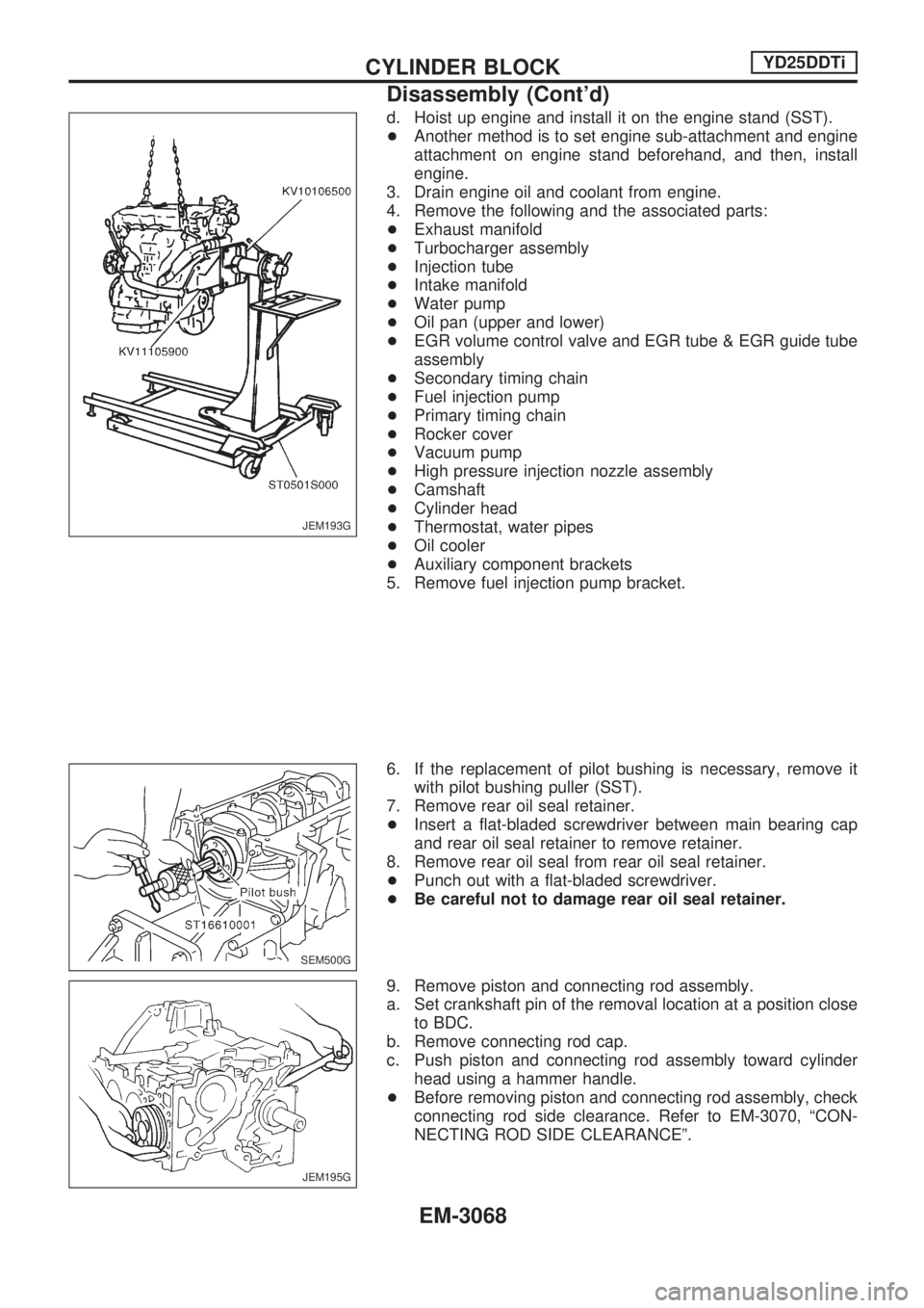
d. Hoist up engine and install it on the engine stand (SST).
+Another method is to set engine sub-attachment and engine
attachment on engine stand beforehand, and then, install
engine.
3. Drain engine oil and coolant from engine.
4. Remove the following and the associated parts:
+Exhaust manifold
+Turbocharger assembly
+Injection tube
+Intake manifold
+Water pump
+Oil pan (upper and lower)
+EGR volume control valve and EGR tube & EGR guide tube
assembly
+Secondary timing chain
+Fuel injection pump
+Primary timing chain
+Rocker cover
+Vacuum pump
+High pressure injection nozzle assembly
+Camshaft
+Cylinder head
+Thermostat, water pipes
+Oil cooler
+Auxiliary component brackets
5. Remove fuel injection pump bracket.
6. If the replacement of pilot bushing is necessary, remove it
with pilot bushing puller (SST).
7. Remove rear oil seal retainer.
+Insert a flat-bladed screwdriver between main bearing cap
and rear oil seal retainer to remove retainer.
8. Remove rear oil seal from rear oil seal retainer.
+Punch out with a flat-bladed screwdriver.
+Be careful not to damage rear oil seal retainer.
9. Remove piston and connecting rod assembly.
a. Set crankshaft pin of the removal location at a position close
to BDC.
b. Remove connecting rod cap.
c. Push piston and connecting rod assembly toward cylinder
head using a hammer handle.
+Before removing piston and connecting rod assembly, check
connecting rod side clearance. Refer to EM-3070, ªCON-
NECTING ROD SIDE CLEARANCEº.
JEM193G
SEM500G
JEM195G
CYLINDER BLOCKYD25DDTi
Disassembly (Cont'd)
EM-3068
Page 949 of 1306
Refer to SDS (EM-3094).
+When replacing the piston, check the cylinder block surface
for scratches or seizure. If scratches or seizure is found,
hone or replace the cylinder block.
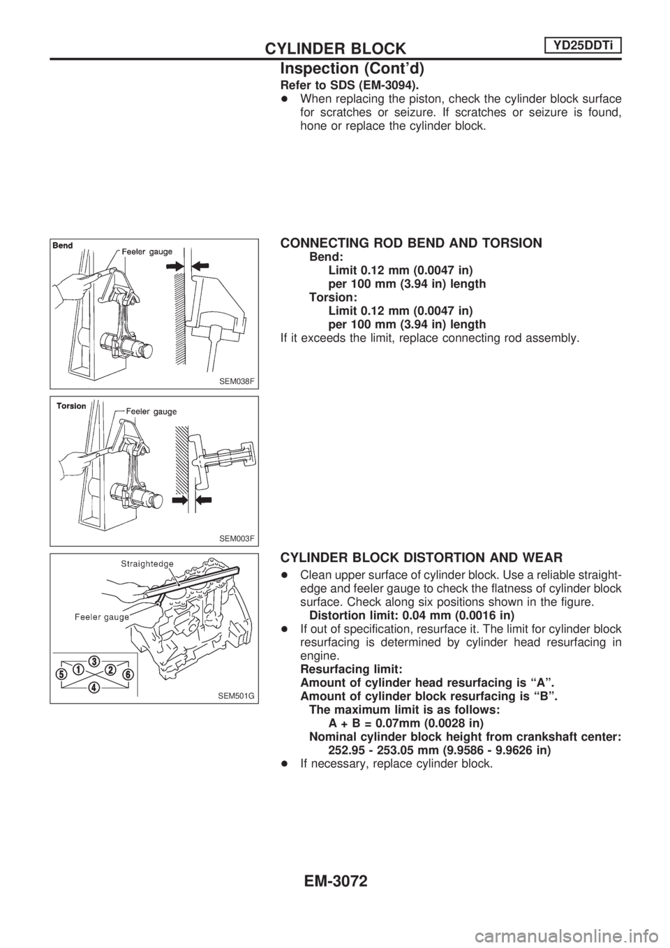
CONNECTING ROD BEND AND TORSION
Bend:
Limit 0.12 mm (0.0047 in)
per 100 mm (3.94 in) length
Torsion:
Limit 0.12 mm (0.0047 in)
per 100 mm (3.94 in) length
If it exceeds the limit, replace connecting rod assembly.
CYLINDER BLOCK DISTORTION AND WEAR
+Clean upper surface of cylinder block. Use a reliable straight-
edge and feeler gauge to check the flatness of cylinder block
surface. Check along six positions shown in the figure.
Distortion limit: 0.04 mm (0.0016 in)
+If out of specification, resurface it. The limit for cylinder block
resurfacing is determined by cylinder head resurfacing in
engine.
Resurfacing limit:
Amount of cylinder head resurfacing is ªAº.
Amount of cylinder block resurfacing is ªBº.
The maximum limit is as follows:
A+B=0.07mm (0.0028 in)
Nominal cylinder block height from crankshaft center:
252.95 - 253.05 mm (9.9586 - 9.9626 in)
+If necessary, replace cylinder block.
SEM038F
SEM003F
SEM501G
CYLINDER BLOCKYD25DDTi
Inspection (Cont'd)
EM-3072
Page 959 of 1306

CRANKSHAFT
1. Blow air sufficiently into the coolant passage, oil passage in
the cylinder block, inside of crankshaft case, and inside of
cylinder bores to remove any foreign materials.
2. Install oil jet relief valves.
3. Install oil jets.
4. Install main bearings and thrust bearings.
a. Remove debris, dust, and oil from the locations on the cylin-
der block and main bearing caps where bearings are
installed.
b. Install thrust bearing on each side of cylinder block No. 3
housing.
+Install thrust bearings with oil groove facing in the direction
of the crankshaft arm (outside).
c. Be sure to install main bearings in the correct direction.
+Make sure those with oil holes or oil grooves are mounted on
the cylinder block side, and those without oil holes or oil
grooves are on the main cap side.
+Before installing, apply engine oil on the front (inner) surfaces
of bearings. Do not apply oil to the back surfaces, but thor-
oughly clean them.
+Align stopper notches on bearings and install.
+Check the oil holes on cylinder block and those on bearings
are aligned.
5. Install crankshaft to cylinder block.
+Make sure crankshaft rotates smoothly by hand.
6. Install main bearing caps.
+Identify main bearing caps by the punched mark. Install
correctly, matching the journal No. on the bearing cap and
the journal, with the front mark facing forward.
+Main bearing caps are commonly processed with the cylin-
der block. Therefore, caps and cylinder block should be
replaced as a set.
JEM223G
JEM224G
JEM213G
JEM225G
CYLINDER BLOCKYD25DDTi
Assembly (Cont'd)
EM-3082
Page 960 of 1306
7. Check the main bearing cap bolts for deformation.
Refer to EM-3079, ªMAIN BEARING CAP BOLT DEFORMA-
TIONº.
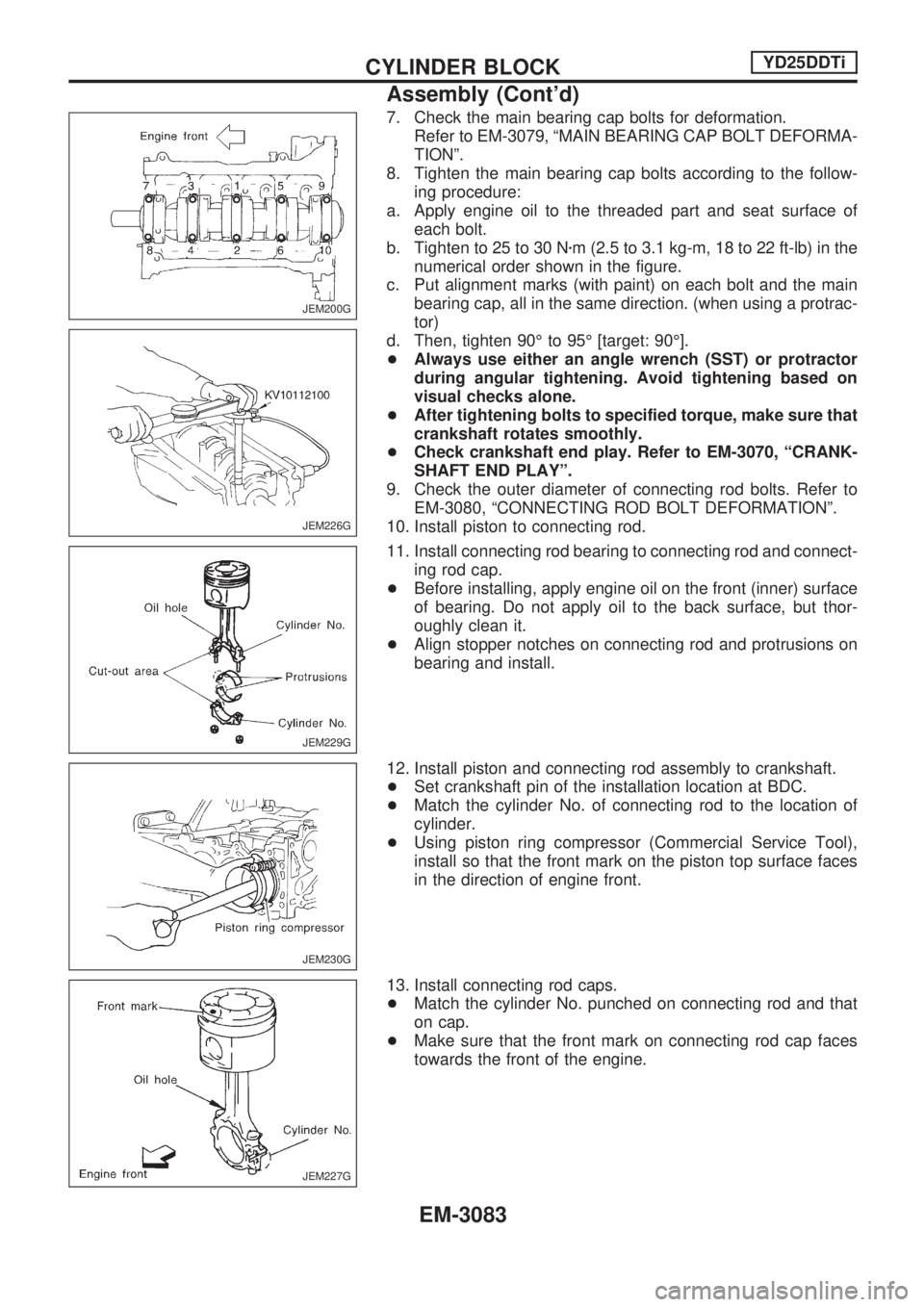
8. Tighten the main bearing cap bolts according to the follow-
ing procedure:
a. Apply engine oil to the threaded part and seat surface of
each bolt.
b. Tighten to 25 to 30 Nzm (2.5 to 3.1 kg-m, 18 to 22 ft-lb) in the
numerical order shown in the figure.
c. Put alignment marks (with paint) on each bolt and the main
bearing cap, all in the same direction. (when using a protrac-
tor)
d. Then, tighten 90É to 95É [target: 90É].
+Always use either an angle wrench (SST) or protractor
during angular tightening. Avoid tightening based on
visual checks alone.
+After tightening bolts to specified torque, make sure that
crankshaft rotates smoothly.
+Check crankshaft end play. Refer to EM-3070, ªCRANK-
SHAFT END PLAYº.
9. Check the outer diameter of connecting rod bolts. Refer to
EM-3080, ªCONNECTING ROD BOLT DEFORMATIONº.
10. Install piston to connecting rod.
11. Install connecting rod bearing to connecting rod and connect-
ing rod cap.
+Before installing, apply engine oil on the front (inner) surface
of bearing. Do not apply oil to the back surface, but thor-
oughly clean it.
+Align stopper notches on connecting rod and protrusions on
bearing and install.
12. Install piston and connecting rod assembly to crankshaft.
+Set crankshaft pin of the installation location at BDC.
+Match the cylinder No. of connecting rod to the location of
cylinder.
+Using piston ring compressor (Commercial Service Tool),
install so that the front mark on the piston top surface faces
in the direction of engine front.
13. Install connecting rod caps.
+Match the cylinder No. punched on connecting rod and that
on cap.
+Make sure that the front mark on connecting rod cap faces
towards the front of the engine.
JEM200G
JEM226G
JEM229G
JEM230G
JEM227G
CYLINDER BLOCKYD25DDTi
Assembly (Cont'd)
EM-3083
Page 961 of 1306
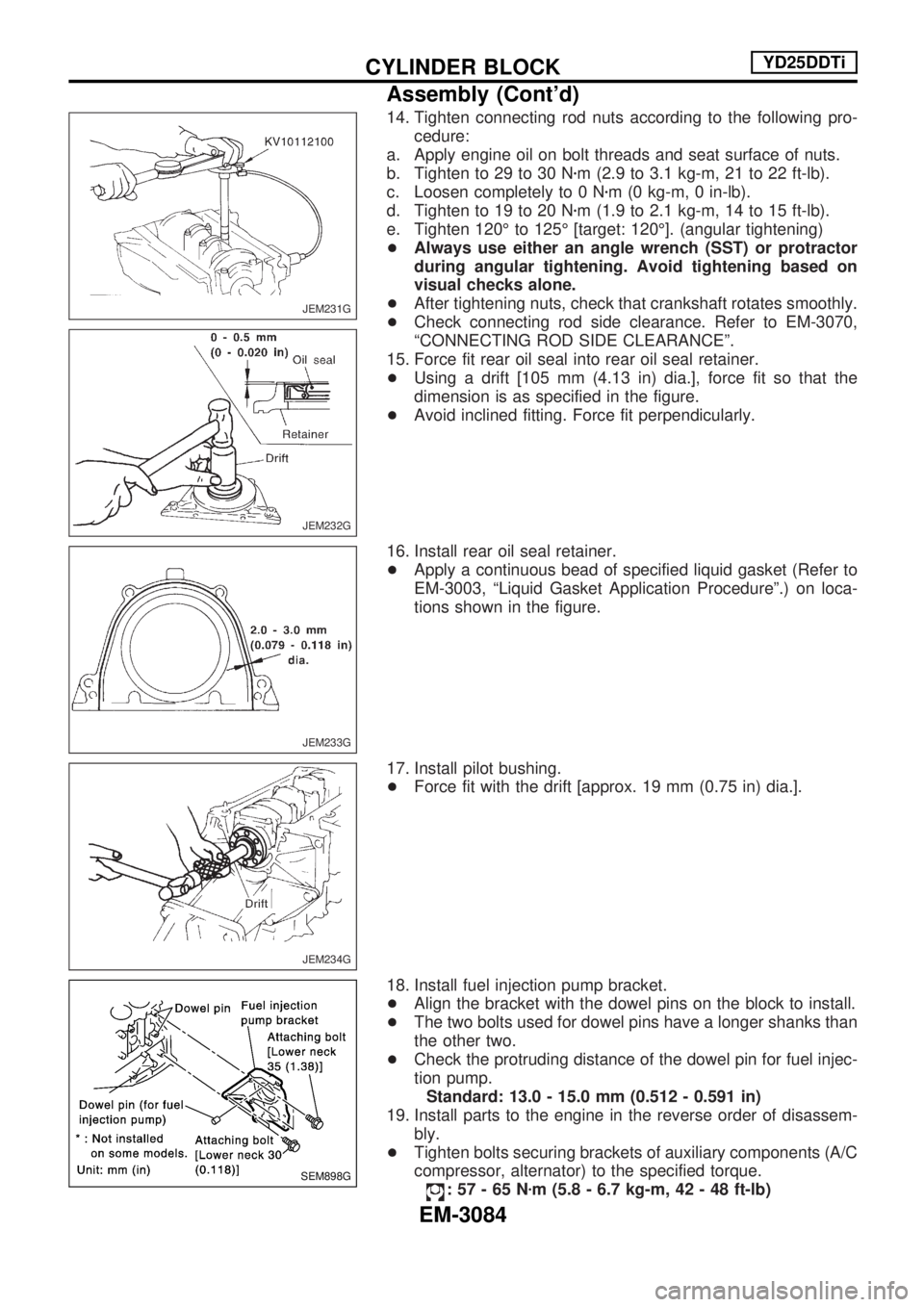
14. Tighten connecting rod nuts according to the following pro-
cedure:
a. Apply engine oil on bolt threads and seat surface of nuts.
b. Tighten to 29 to 30 Nzm (2.9 to 3.1 kg-m, 21 to 22 ft-lb).
c. Loosen completely to 0 Nzm (0 kg-m, 0 in-lb).
d. Tighten to 19 to 20 Nzm (1.9 to 2.1 kg-m, 14 to 15 ft-lb).
e. Tighten 120É to 125É [target: 120É]. (angular tightening)
+Always use either an angle wrench (SST) or protractor
during angular tightening. Avoid tightening based on
visual checks alone.
+After tightening nuts, check that crankshaft rotates smoothly.
+Check connecting rod side clearance. Refer to EM-3070,
ªCONNECTING ROD SIDE CLEARANCEº.
15. Force fit rear oil seal into rear oil seal retainer.
+Using a drift [105 mm (4.13 in) dia.], force fit so that the
dimension is as specified in the figure.
+Avoid inclined fitting. Force fit perpendicularly.
16. Install rear oil seal retainer.
+Apply a continuous bead of specified liquid gasket (Refer to
EM-3003, ªLiquid Gasket Application Procedureº.) on loca-
tions shown in the figure.
17. Install pilot bushing.
+Force fit with the drift [approx. 19 mm (0.75 in) dia.].
18. Install fuel injection pump bracket.
+Align the bracket with the dowel pins on the block to install.
+The two bolts used for dowel pins have a longer shanks than
the other two.
+Check the protruding distance of the dowel pin for fuel injec-
tion pump.
Standard: 13.0 - 15.0 mm (0.512 - 0.591 in)
19. Install parts to the engine in the reverse order of disassem-
bly.
+Tighten bolts securing brackets of auxiliary components (A/C
compressor, alternator) to the specified torque.
:57-65Nzm (5.8 - 6.7 kg-m, 42 - 48 ft-lb)
JEM231G
JEM232G
JEM233G
JEM234G
SEM898G
CYLINDER BLOCKYD25DDTi
Assembly (Cont'd)
EM-3084
Page 975 of 1306
HEATER &
AIR CONDITIONER
SECTION
HA
MODIFICATION NOTICE:
+Wiring Diagrams have been changed.
+Thermo switch has been abolished.
+A/C cycle for YD engine has been added.
CONTENTS
MANUAL AND AUTO
PRECAUTIONS AND PREPARATION............... 3002
Precautions for Refrigerant Connection .......... 3002
MANUAL
TROUBLE DIAGNOSES..................................... 3004
Wiring Diagram - HEATER -............................ 3004
Circuit Diagram - A/C, M - ............................... 3005
Wiring Diagram - A/C, M -/LHD Models with
KA, YD Engine ................................................. 3006
Wiring Diagram - A/C, M -/RHD Models with
KA, YD Engine ................................................. 3009
Magnet Clutch .................................................. 3012
AUTO
TROUBLE DIAGNOSES..................................... 3020
Circuit Diagram - A/C, A -................................ 3020
Wiring Diagram - A/C, A -................................ 3021
Magnet Clutch .................................................. 3026
SERVICE PROCEDURES................................... 3030
Refrigerant Lines.............................................. 3030
MANUAL AND AUTO
SERVICE PROCEDURES................................... 3031
Checking Refrigerant Leaks ............................ 3031
SERVICE PROCEDURES................................... 3032
Compressor Mounting...................................... 3032
MANUAL AND AUTO
SERVICE DATA AND SPECIFICATIONS
(SDS).................................................................... 3033
General Specifications ..................................... 3033
Inspection and Adjustment .............................. 3033
HA
Page 986 of 1306
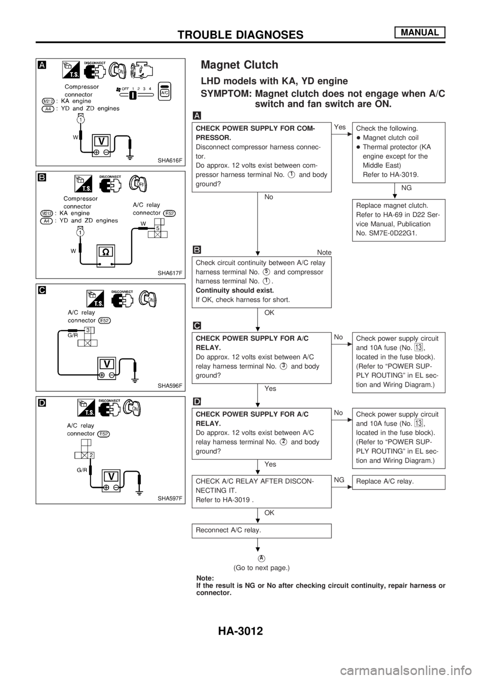
Magnet Clutch
LHD models with KA, YD engine
SYMPTOM: Magnet clutch does not engage when A/C
switch and fan switch are ON.
CHECK POWER SUPPLY FOR COM-
PRESSOR.
Disconnect compressor harness connec-
tor.
Do approx. 12 volts exist between com-
pressor harness terminal No.
V1and body
ground?
No
cYes
Check the following.
+Magnet clutch coil
+Thermal protector (KA
engine except for the
Middle East)
Refer to HA-3019.
NG
Replace magnet clutch.
Refer to HA-69 in D22 Ser-
vice Manual, Publication
No. SM7E-0D22G1.
Note
Check circuit continuity between A/C relay
harness terminal No.
V5and compressor
harness terminal No.
V1.
Continuity should exist.
If OK, check harness for short.
OK
CHECK POWER SUPPLY FOR A/C
RELAY.
Do approx. 12 volts exist between A/C
relay harness terminal No.
V3and body
ground?
Yes
cNo
Check power supply circuit
and 10A fuse (No.
13,
located in the fuse block).
(Refer to ªPOWER SUP-
PLY ROUTINGº in EL sec-
tion and Wiring Diagram.)
CHECK POWER SUPPLY FOR A/C
RELAY.
Do approx. 12 volts exist between A/C
relay harness terminal No.
V2and body
ground?
Yes
cNo
Check power supply circuit
and 10A fuse (No.
13,
located in the fuse block).
(Refer to ªPOWER SUP-
PLY ROUTINGº in EL sec-
tion and Wiring Diagram.)
CHECK A/C RELAY AFTER DISCON-
NECTING IT.
Refer to HA-3019 .
OK
cNG
Replace A/C relay.
Reconnect A/C relay.
VA
(Go to next page.)
Note:
If the result is NG or No after checking circuit continuity, repair harness or
connector.
SHA616F
SHA617F
SHA596F
SHA597F
.
.
.
.
.
.
.
TROUBLE DIAGNOSESMANUAL
HA-3012