2001 NISSAN PICK-UP check engine
[x] Cancel search: check enginePage 748 of 1306
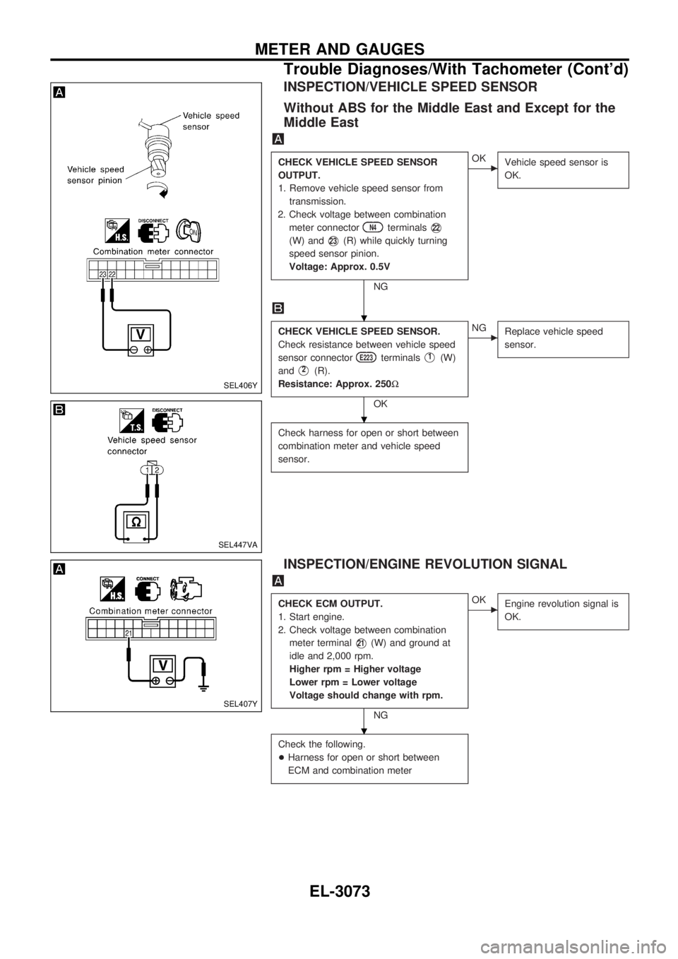
INSPECTION/VEHICLE SPEED SENSOR
Without ABS for the Middle East and Except for the
Middle East
CHECK VEHICLE SPEED SENSOR
OUTPUT.
1. Remove vehicle speed sensor from
transmission.
2. Check voltage between combination
meter connector
N4terminalsV22
(W) andV23(R) while quickly turning
speed sensor pinion.
Voltage: Approx. 0.5V
NG
cOK
Vehicle speed sensor is
OK.
CHECK VEHICLE SPEED SENSOR.
Check resistance between vehicle speed
sensor connector
E223terminalsV1(W)
and
V2(R).
Resistance: Approx. 250W
OK
cNG
Replace vehicle speed
sensor.
Check harness for open or short between
combination meter and vehicle speed
sensor.
INSPECTION/ENGINE REVOLUTION SIGNAL
CHECK ECM OUTPUT.
1. Start engine.
2. Check voltage between combination
meter terminal
V21(W) and ground at
idle and 2,000 rpm.
Higher rpm = Higher voltage
Lower rpm = Lower voltage
Voltage should change with rpm.
NG
cOK
Engine revolution signal is
OK.
Check the following.
+Harness for open or short between
ECM and combination meter
SEL406Y
SEL447VA
SEL407Y
.
.
.
METER AND GAUGES
Trouble Diagnoses/With Tachometer (Cont'd)
EL-3073
Page 823 of 1306
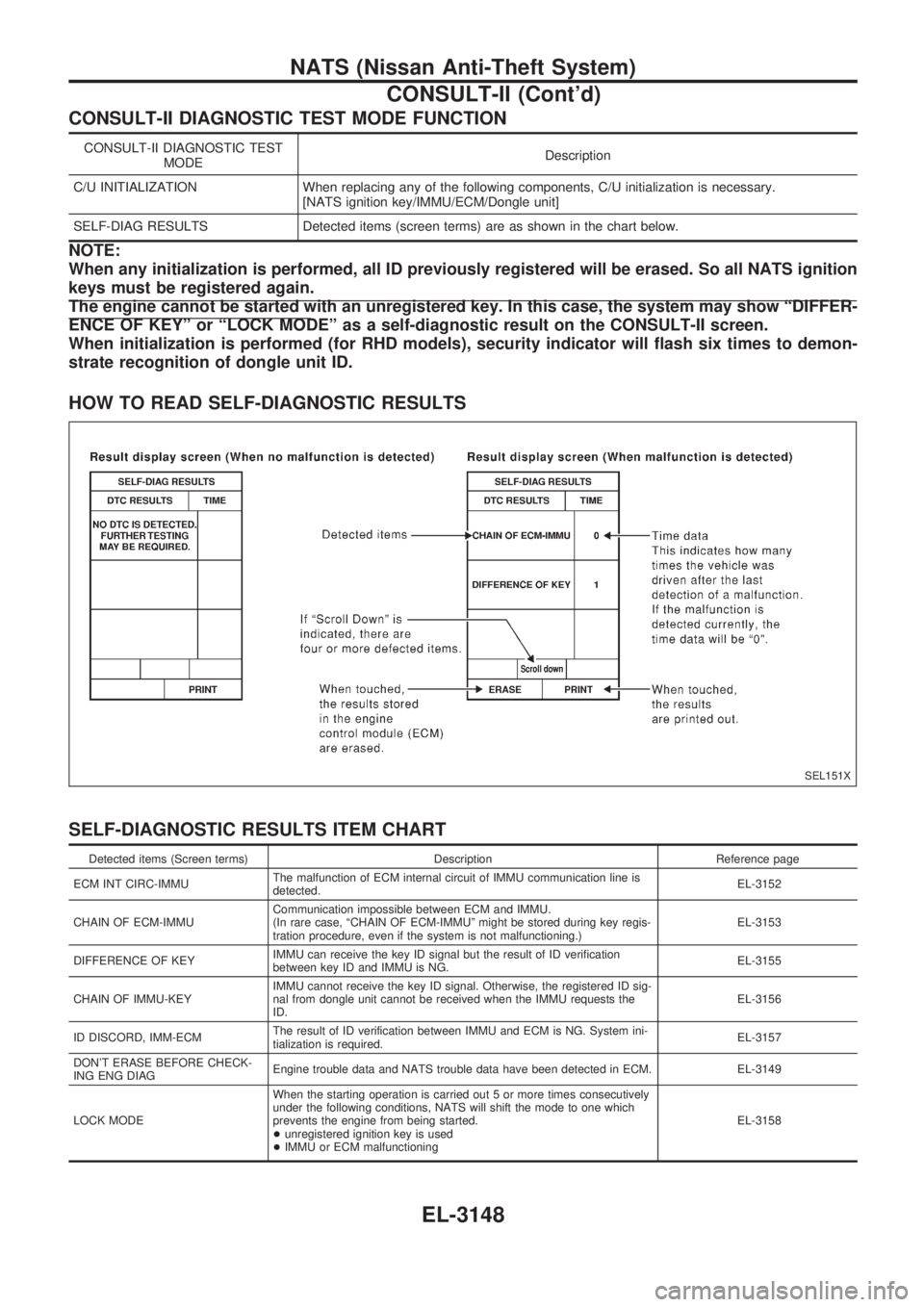
CONSULT-II DIAGNOSTIC TEST MODE FUNCTION
CONSULT-II DIAGNOSTIC TEST
MODEDescription
C/U INITIALIZATION When replacing any of the following components, C/U initialization is necessary.
[NATS ignition key/IMMU/ECM/Dongle unit]
SELF-DIAG RESULTS Detected items (screen terms) are as shown in the chart below.
NOTE:
When any initialization is performed, all ID previously registered will be erased. So all NATS ignition
keys must be registered again.
The engine cannot be started with an unregistered key. In this case, the system may show ªDIFFER-
ENCE OF KEYº or ªLOCK MODEº as a self-diagnostic result on the CONSULT-II screen.
When initialization is performed (for RHD models), security indicator will flash six times to demon-
strate recognition of dongle unit ID.
HOW TO READ SELF-DIAGNOSTIC RESULTS
SELF-DIAGNOSTIC RESULTS ITEM CHART
Detected items (Screen terms) Description Reference page
ECM INT CIRC-IMMUThe malfunction of ECM internal circuit of IMMU communication line is
detected.EL-3152
CHAIN OF ECM-IMMUCommunication impossible between ECM and IMMU.
(In rare case, ªCHAIN OF ECM-IMMUº might be stored during key regis-
tration procedure, even if the system is not malfunctioning.)EL-3153
DIFFERENCE OF KEYIMMU can receive the key ID signal but the result of ID verification
between key ID and IMMU is NG.EL-3155
CHAIN OF IMMU-KEYIMMU cannot receive the key ID signal. Otherwise, the registered ID sig-
nal from dongle unit cannot be received when the IMMU requests the
ID.EL-3156
ID DISCORD, IMM-ECMThe result of ID verification between IMMU and ECM is NG. System ini-
tialization is required.EL-3157
DON'T ERASE BEFORE CHECK-
ING ENG DIAGEngine trouble data and NATS trouble data have been detected in ECM. EL-3149
LOCK MODEWhen the starting operation is carried out 5 or more times consecutively
under the following conditions, NATS will shift the mode to one which
prevents the engine from being started.
+unregistered ignition key is used
+IMMU or ECM malfunctioningEL-3158
SEL151X
NATS (Nissan Anti-Theft System)
CONSULT-II (Cont'd)
EL-3148
Page 824 of 1306
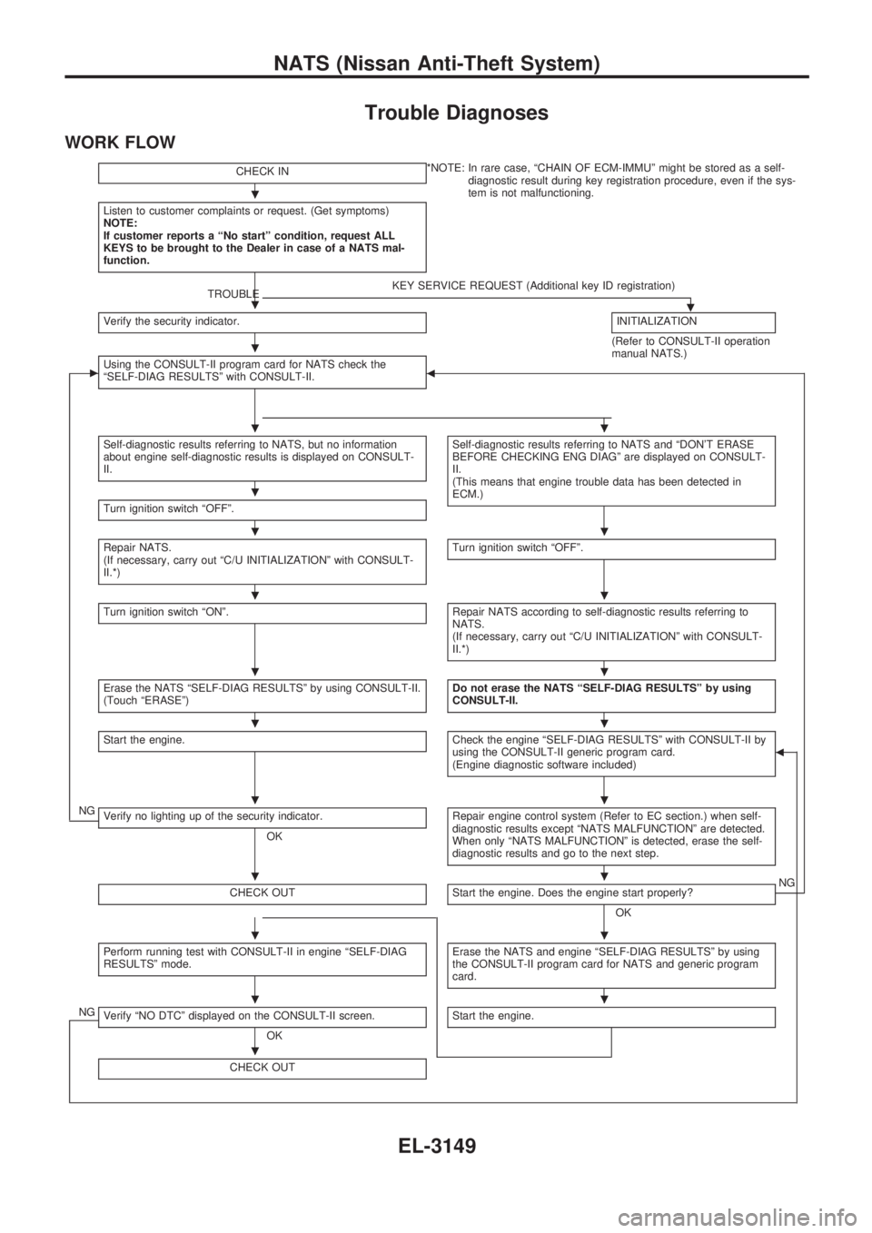
Trouble Diagnoses
WORK FLOW
CHECK IN*NOTE: In rare case, ªCHAIN OF ECM-IMMUº might be stored as a self-
diagnostic result during key registration procedure, even if the sys-
tem is not malfunctioning.
Listen to customer complaints or request. (Get symptoms)
NOTE:
If customer reports a ªNo startº condition, request ALL
KEYS to be brought to the Dealer in case of a NATS mal-
function.
TROUBLEKEY SERVICE REQUEST (Additional key ID registration).Verify the security indicator.INITIALIZATION
(Refer to CONSULT-II operation
manual NATS.)
cUsing the CONSULT-II program card for NATS check the
ªSELF-DIAG RESULTSº with CONSULT-II.b
Self-diagnostic results referring to NATS, but no information
about engine self-diagnostic results is displayed on CONSULT-
II.Self-diagnostic results referring to NATS and ªDON'T ERASE
BEFORE CHECKING ENG DIAGº are displayed on CONSULT-
II.
(This means that engine trouble data has been detected in
ECM.)
Turn ignition switch ªOFFº.
Repair NATS.
(If necessary, carry out ªC/U INITIALIZATIONº with CONSULT-
II.*)Turn ignition switch ªOFFº.
Turn ignition switch ªONº.Repair NATS according to self-diagnostic results referring to
NATS.
(If necessary, carry out ªC/U INITIALIZATIONº with CONSULT-
II.*)
Erase the NATS ªSELF-DIAG RESULTSº by using CONSULT-II.
(Touch ªERASEº)Do not erase the NATS ªSELF-DIAG RESULTSº by using
CONSULT-II.
Start the engine.Check the engine ªSELF-DIAG RESULTSº with CONSULT-II by
using the CONSULT-II generic program card.
(Engine diagnostic software included)b
NGVerify no lighting up of the security indicator.
OKRepair engine control system (Refer to EC section.) when self-
diagnostic results except ªNATS MALFUNCTIONº are detected.
When only ªNATS MALFUNCTIONº is detected, erase the self-
diagnostic results and go to the next step.
CHECK OUTStart the engine. Does the engine start properly?
OKNG
Perform running test with CONSULT-II in engine ªSELF-DIAG
RESULTSº mode.Erase the NATS and engine ªSELF-DIAG RESULTSº by using
the CONSULT-II program card for NATS and generic program
card.
NGVerify ªNO DTCº displayed on the CONSULT-II screen.
OKStart the engine.
CHECK OUT
.
.
.
..
.
..
..
..
..
..
..
..
..
.
NATS (Nissan Anti-Theft System)
EL-3149
Page 828 of 1306
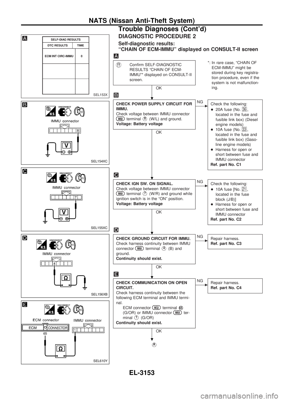
DIAGNOSTIC PROCEDURE 2
Self-diagnostic results:
ªCHAIN OF ECM-IMMUº displayed on CONSULT-II screen
Confirm SELF-DIAGNOSTIC
RESULTS ªCHAIN OF ECM-
IMMUº* displayed on CONSULT-II
screen.
OK*: In rare case, ªCHAIN OF
ECM-IMMUº might be
stored during key registra-
tion procedure, even if the
system is not malfunction-
ing.
CHECK POWER SUPPLY CIRCUIT FOR
IMMU.
Check voltage between IMMU connector
M68terminalV8(W/L) and ground.
Voltage: Battery voltage
OK
cNG
Check the following:
+20A fuse (No.
36,
located in the fuse and
fusible link box) (Diesel
engine models)
+10A fuse (No.
33,
located in the fuse and
fusible link box) (Gaso-
line engine models)
+Harness for open or
short between fuse and
IMMU connector
Ref. part No. C1
CHECK IGN SW. ON SIGNAL.
Check voltage between IMMU connector
M68terminalV7(W/R) and ground while
ignition switch is in the ªONº position.
Voltage: Battery voltage
OK
cNG
Check the following:
+10A fuse [No.
21,
located in the fuse
block (J/B)]
+Harness for open or
short between fuse and
IMMU connector
Ref. part No. C2
CHECK GROUND CIRCUIT FOR IMMU.
Check harness continuity between IMMU
connector
M68terminalV4(B) and
ground.
Continuity should exist.
OK
cNG
Repair harness.
Ref. part No. C3
CHECK COMMUNICATION ON OPEN
CIRCUIT.
Check harness continuity between the
following ECM terminal and IMMU termi-
nal.
ECM connector
M32terminalV65
(G/OR) or IMMU connectorM68ter-
minal
V1(G/OR)
Continuity should exist.
OK
cNG
Repair harness.
Ref. part No. C4
VA
SEL153X
SEL154XC
SEL155XC
SEL156XB
SEL610Y
.
.
.
.
.
NATS (Nissan Anti-Theft System)
Trouble Diagnoses (Cont'd)
EL-3153
Page 831 of 1306
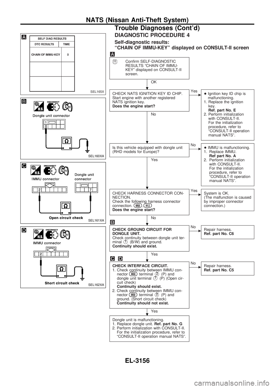
DIAGNOSTIC PROCEDURE 4
Self-diagnostic results:
ªCHAIN OF IMMU-KEYº displayed on CONSULT-II screen
Confirm SELF-DIAGNOSTIC
RESULTS ªCHAIN OF IMMU-
KEYº displayed on CONSULT-II
screen.
OK
CHECK NATS IGNITION KEY ID CHIP.
Start engine with another registered
NATS ignition key.
Does the engine start?
No
cYes
+Ignition key ID chip is
malfunctioning.
1. Replace the ignition
key.
Ref. part No. E
2. Perform initialization
with CONSULT-II.
For the initialization
procedure, refer to
ªCONSULT-II operation
manual NATSº.
Is this vehicle equipped with dongle unit
(RHD models for Europe)?
Yes
cNo
+IMMU is malfunctioning.
1. Replace IMMU.
Ref part No. A
2. Perform initialization
with CONSULT-II.
For the initialization
procedure, refer to
ªCONSULT-II operation
manual NATSº.
CHECK HARNESS CONNECTOR CON-
NECTION.
Check the following harness connector
connection.
M68,N12Does the engine start?
No
cYes
System is OK.
(The malfunction is caused
by improper connector
connection.)
CHECK GROUND CIRCUIT FOR
DONGLE UNIT.
Check continuity between dongle unit ter-
minal
V1(B/W) and ground.
Continuity should exist.
Yes
cNo
Repair harness.
Ref. part No. C6
CHECK INTERFACE CIRCUIT.
1. Check continuity between IMMU con-
nector
M68terminalV2(P) and
dongle unit terminalV7(P) (Open cir-
cuit check)
Continuity should exist.
2. Check continuity between IMMU con-
nector
M68terminalV2(P) and
ground. (Short circuit check)
Continuity should not exist.
Yes
cNo
Repair harness.
Ref. part No. C5
Dongle unit is malfunctioning.
1. Replace dongle unit.Ref. part No. G
2. Perform initialization with CONSULT-II.
For the initialization procedure, refer to
ªCONSULT-II operation manual NATSº.
SEL165X
SEL160XA
SEL161XA
SEL162XA
.
.
.
.
.
.
NATS (Nissan Anti-Theft System)
Trouble Diagnoses (Cont'd)
EL-3156
Page 833 of 1306
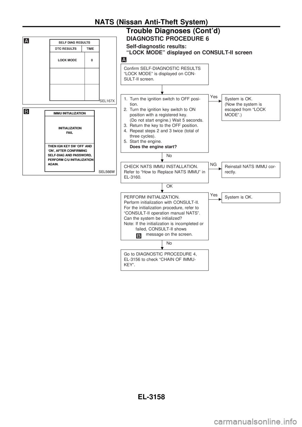
DIAGNOSTIC PROCEDURE 6
Self-diagnostic results:
ªLOCK MODEº displayed on CONSULT-II screen
Confirm SELF-DIAGNOSTIC RESULTS
ªLOCK MODEº is displayed on CON-
SULT-II screen.
1. Turn the ignition switch to OFF posi-
tion.
2. Turn the ignition key switch to ON
position with a registered key.
(Do not start engine.) Wait 5 seconds.
3. Return the key to the OFF position.
4. Repeat steps 2 and 3 twice (total of
three cycles).
5. Start the engine.
Does the engine start?
No
cYes
System is OK.
(Now the system is
escaped from ªLOCK
MODEº.)
CHECK NATS IMMU INSTALLATION.
Refer to ªHow to Replace NATS IMMUº in
EL-3160.
OK
cNG
Reinstall NATS IMMU cor-
rectly.
PERFORM INITIALIZATION.
Perform initialization with CONSULT-II.
For the initialization procedure, refer to
ªCONSULT-II operation manual NATSº.
Can the system be initialized?
Note: If the initialization is incompleted or
failed, CONSULT-II shows
message on the screen.
No
cYes
System is OK.
Go to DIAGNOSTIC PROCEDURE 4,
EL-3156 to check ªCHAIN OF IMMU-
KEYº.
SEL167X
SEL566W
.
.
.
.
NATS (Nissan Anti-Theft System)
Trouble Diagnoses (Cont'd)
EL-3158
Page 834 of 1306
![NISSAN PICK-UP 2001 Repair Manual DIAGNOSTIC PROCEDURE 7
ªSECURITY IND. DOES NOT LIGHT UPº
Check 10A fuse [No.6, located in the
fuse block (J/B)].
OK
cNG
Replace fuse.
NATS INITIALIZATION
1) Install the 10A fuse.
2) Perform initiali NISSAN PICK-UP 2001 Repair Manual DIAGNOSTIC PROCEDURE 7
ªSECURITY IND. DOES NOT LIGHT UPº
Check 10A fuse [No.6, located in the
fuse block (J/B)].
OK
cNG
Replace fuse.
NATS INITIALIZATION
1) Install the 10A fuse.
2) Perform initiali](/manual-img/5/57372/w960_57372-833.png)
DIAGNOSTIC PROCEDURE 7
ªSECURITY IND. DOES NOT LIGHT UPº
Check 10A fuse [No.6, located in the
fuse block (J/B)].
OK
cNG
Replace fuse.
NATS INITIALIZATION
1) Install the 10A fuse.
2) Perform initialization with CON-
SULT-II.
For the operation of
initialization, refer to ªCON-
SULT-II operation manual
NATSº.
Turn ignition switch ªOFFº.
Start engine and turn ignition switch
ªOFFº.
Check the security ind. lighting.
NG
cOK
END
Check voltage between security ind. con-
nectorM55terminalV1(R/G) and
ground.
Voltage: Battery voltage
OK
cNG
Check harness for open or
short between fuse and
security ind.
CHECK INDICATOR LAMP.
OK
cNG
Repair harness.
CHECK NATS IMMU FUNCTION.
1. Connect NATS IMMU connectorM68.
2. Disconnect security ind. connector
M55.
3. Check continuity between NATS IMMU
connector
M68terminalV6(L) and
ground.
Continuity should exist intermit-
tently.
OK
cNG
NATS IMMU is malfunc-
tioning. Replace IMMU.
Perform initializa-
tion with CON-
SULT-II.
For the operation
of initialization,
refer to ªCON-
SULT-II operation
manual NATSº.
Check harness for open or short between
security indicator and NATS IMMU.
SEL931UC
SEL164XA
.
.
.
.
.
.
.
.
.
NATS (Nissan Anti-Theft System)
Trouble Diagnoses (Cont'd)
EL-3159
Page 872 of 1306
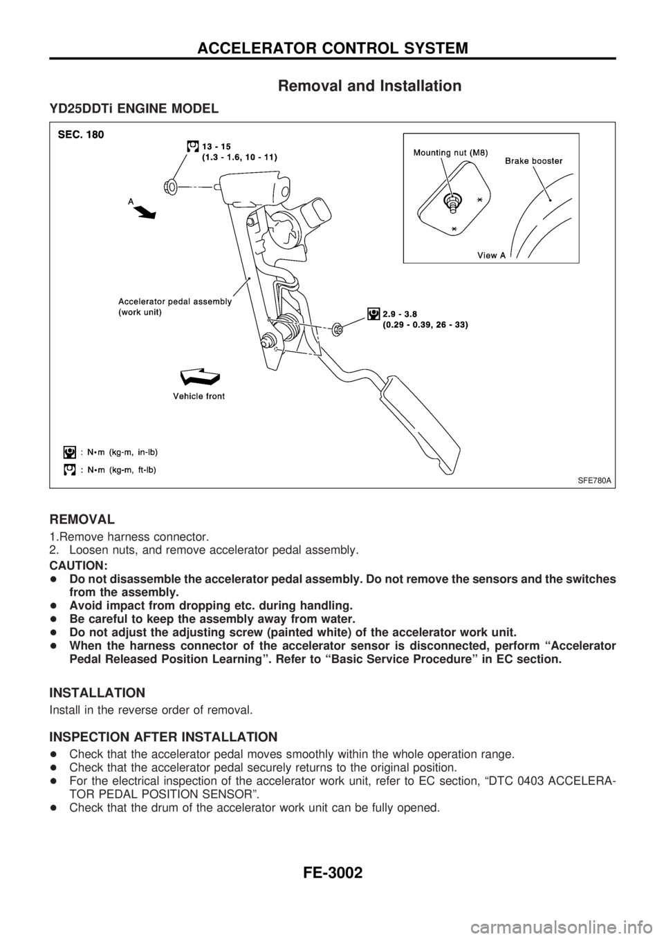
Removal and Installation
YD25DDTi ENGINE MODEL
REMOVAL
1.Remove harness connector.
2. Loosen nuts, and remove accelerator pedal assembly.
CAUTION:
+Do not disassemble the accelerator pedal assembly. Do not remove the sensors and the switches
from the assembly.
+Avoid impact from dropping etc. during handling.
+Be careful to keep the assembly away from water.
+Do not adjust the adjusting screw (painted white) of the accelerator work unit.
+When the harness connector of the accelerator sensor is disconnected, perform ªAccelerator
Pedal Released Position Learningº. Refer to ªBasic Service Procedureº in EC section.
INSTALLATION
Install in the reverse order of removal.
INSPECTION AFTER INSTALLATION
+Check that the accelerator pedal moves smoothly within the whole operation range.
+Check that the accelerator pedal securely returns to the original position.
+For the electrical inspection of the accelerator work unit, refer to EC section, ªDTC 0403 ACCELERA-
TOR PEDAL POSITION SENSORº.
+Check that the drum of the accelerator work unit can be fully opened.
SFE780A
ACCELERATOR CONTROL SYSTEM
FE-3002