2001 NISSAN PICK-UP check engine
[x] Cancel search: check enginePage 625 of 1306
Component Description
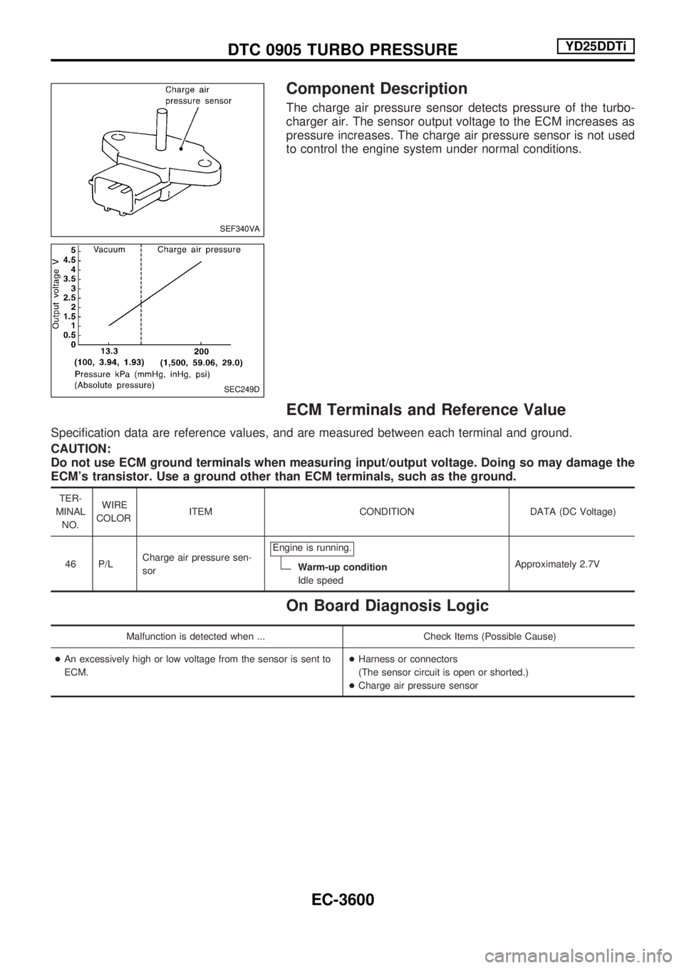
The charge air pressure sensor detects pressure of the turbo-
charger air. The sensor output voltage to the ECM increases as
pressure increases. The charge air pressure sensor is not used
to control the engine system under normal conditions.
ECM Terminals and Reference Value
Specification data are reference values, and are measured between each terminal and ground.
CAUTION:
Do not use ECM ground terminals when measuring input/output voltage. Doing so may damage the
ECM's transistor. Use a ground other than ECM terminals, such as the ground.
TER-
MINAL
NO.WIRE
COLORITEM CONDITION DATA (DC Voltage)
46 P/LCharge air pressure sen-
sorEngine is running.
Warm-up condition
Idle speedApproximately 2.7V
On Board Diagnosis Logic
Malfunction is detected when ... Check Items (Possible Cause)
+An excessively high or low voltage from the sensor is sent to
ECM.+Harness or connectors
(The sensor circuit is open or shorted.)
+Charge air pressure sensor
SEF340VA
SEC249D
DTC 0905 TURBO PRESSUREYD25DDTi
EC-3600
Page 628 of 1306
Diagnostic Procedure
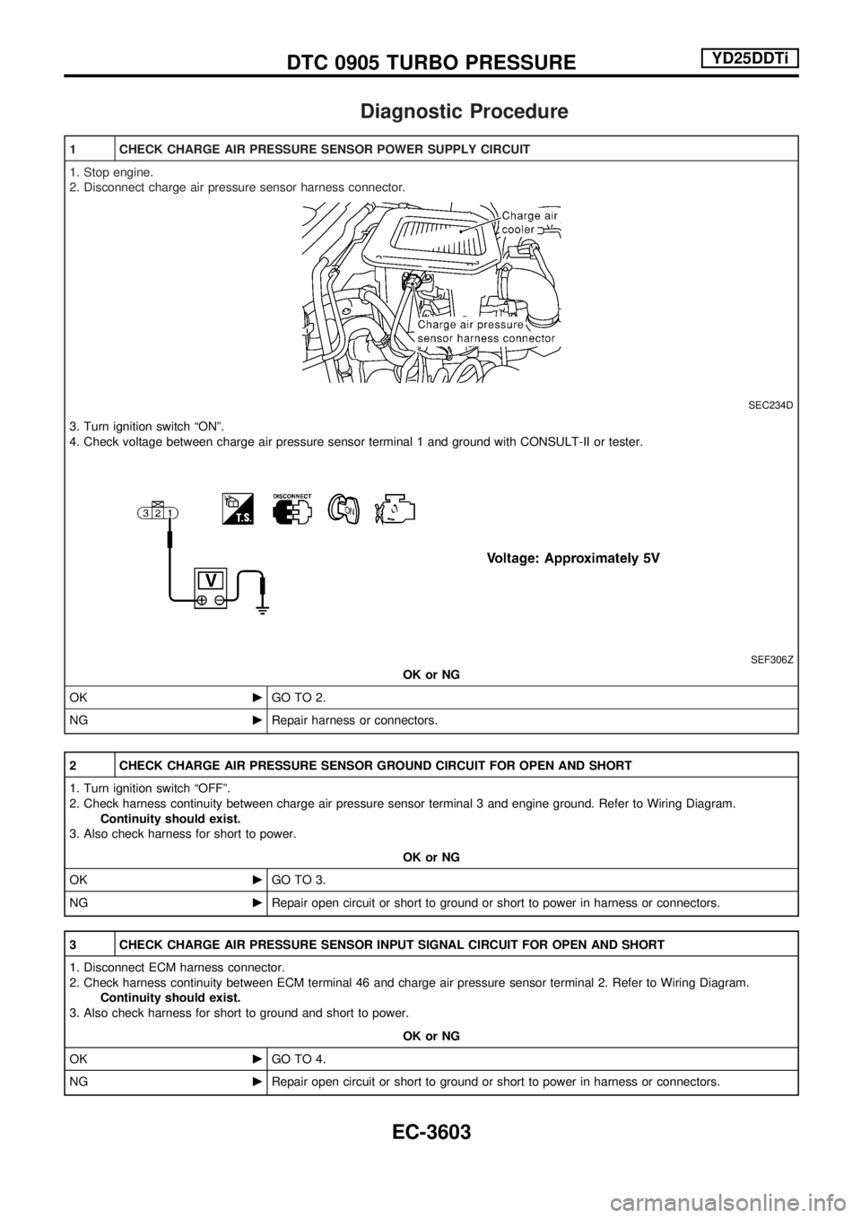
1 CHECK CHARGE AIR PRESSURE SENSOR POWER SUPPLY CIRCUIT
1. Stop engine.
2. Disconnect charge air pressure sensor harness connector.
SEC234D
3. Turn ignition switch ªONº.
4. Check voltage between charge air pressure sensor terminal 1 and ground with CONSULT-II or tester.
SEF306Z
OK or NG
OKcGO TO 2.
NGcRepair harness or connectors.
2 CHECK CHARGE AIR PRESSURE SENSOR GROUND CIRCUIT FOR OPEN AND SHORT
1. Turn ignition switch ªOFFº.
2. Check harness continuity between charge air pressure sensor terminal 3 and engine ground. Refer to Wiring Diagram.
Continuity should exist.
3. Also check harness for short to power.
OK or NG
OKcGO TO 3.
NGcRepair open circuit or short to ground or short to power in harness or connectors.
3 CHECK CHARGE AIR PRESSURE SENSOR INPUT SIGNAL CIRCUIT FOR OPEN AND SHORT
1. Disconnect ECM harness connector.
2. Check harness continuity between ECM terminal 46 and charge air pressure sensor terminal 2. Refer to Wiring Diagram.
Continuity should exist.
3. Also check harness for short to ground and short to power.
OK or NG
OKcGO TO 4.
NGcRepair open circuit or short to ground or short to power in harness or connectors.
DTC 0905 TURBO PRESSUREYD25DDTi
EC-3603
Page 629 of 1306
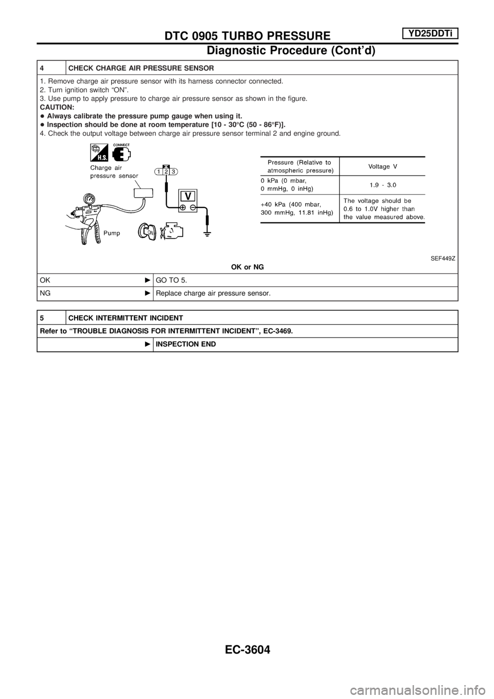
4 CHECK CHARGE AIR PRESSURE SENSOR
1. Remove charge air pressure sensor with its harness connector connected.
2. Turn ignition switch ªONº.
3. Use pump to apply pressure to charge air pressure sensor as shown in the figure.
CAUTION:
+Always calibrate the pressure pump gauge when using it.
+Inspection should be done at room temperature [10 - 30ÉC (50 - 86ÉF)].
4. Check the output voltage between charge air pressure sensor terminal 2 and engine ground.
SEF449Z
OK or NG
OKcGO TO 5.
NGcReplace charge air pressure sensor.
5 CHECK INTERMITTENT INCIDENT
Refer to ªTROUBLE DIAGNOSIS FOR INTERMITTENT INCIDENTº, EC-3469.
cINSPECTION END
DTC 0905 TURBO PRESSUREYD25DDTi
Diagnostic Procedure (Cont'd)
EC-3604
Page 640 of 1306
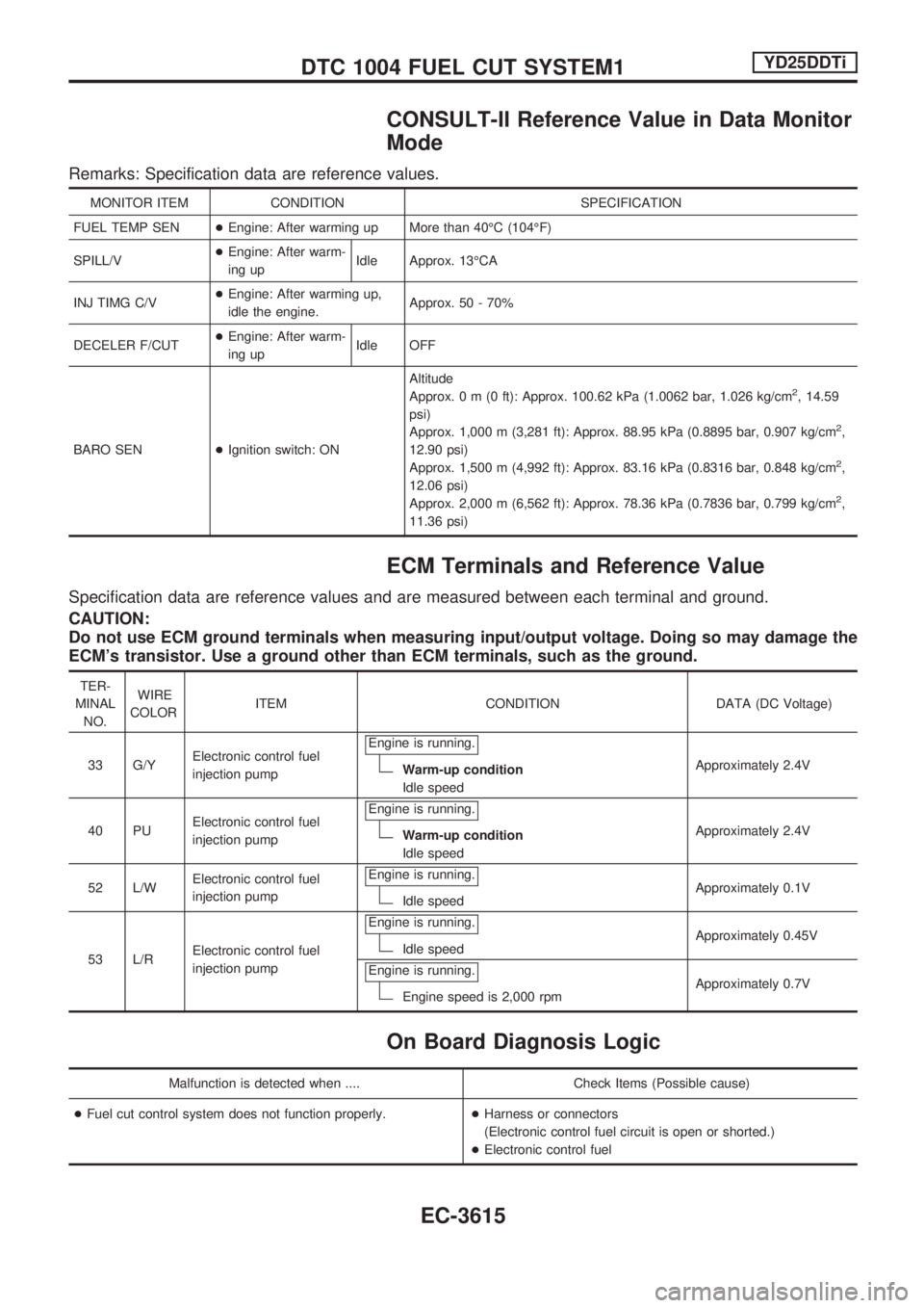
CONSULT-II Reference Value in Data Monitor
Mode
Remarks: Specification data are reference values.
MONITOR ITEM CONDITION SPECIFICATION
FUEL TEMP SEN+Engine: After warming up More than 40ÉC (104ÉF)
SPILL/V+Engine: After warm-
ing upIdle Approx. 13ÉCA
INJ TIMG C/V+Engine: After warming up,
idle the engine.Approx. 50 - 70%
DECELER F/CUT+Engine: After warm-
ing upIdle OFF
BARO SEN+Ignition switch: ONAltitude
Approx.0m(0ft): Approx. 100.62 kPa (1.0062 bar, 1.026 kg/cm
2, 14.59
psi)
Approx. 1,000 m (3,281 ft): Approx. 88.95 kPa (0.8895 bar, 0.907 kg/cm
2,
12.90 psi)
Approx. 1,500 m (4,992 ft): Approx. 83.16 kPa (0.8316 bar, 0.848 kg/cm
2,
12.06 psi)
Approx. 2,000 m (6,562 ft): Approx. 78.36 kPa (0.7836 bar, 0.799 kg/cm
2,
11.36 psi)
ECM Terminals and Reference Value
Specification data are reference values and are measured between each terminal and ground.
CAUTION:
Do not use ECM ground terminals when measuring input/output voltage. Doing so may damage the
ECM's transistor. Use a ground other than ECM terminals, such as the ground.
TER-
MINAL
NO.WIRE
COLORITEM CONDITION DATA (DC Voltage)
33 G/YElectronic control fuel
injection pumpEngine is running.
Warm-up condition
Idle speedApproximately 2.4V
40 PUElectronic control fuel
injection pumpEngine is running.
Warm-up condition
Idle speedApproximately 2.4V
52 L/WElectronic control fuel
injection pumpEngine is running.
Idle speedApproximately 0.1V
53 L/RElectronic control fuel
injection pumpEngine is running.
Idle speedApproximately 0.45V
Engine is running.
Engine speed is 2,000 rpmApproximately 0.7V
On Board Diagnosis Logic
Malfunction is detected when .... Check Items (Possible cause)
+Fuel cut control system does not function properly.+Harness or connectors
(Electronic control fuel circuit is open or shorted.)
+Electronic control fuel
DTC 1004 FUEL CUT SYSTEM1YD25DDTi
EC-3615
Page 645 of 1306
4 DETECT MALFUNCTIONING PART
Check the following.
+Harness connectors E236, M278 (LHD models)
+Harness connectors E236, F35 (RHD models)
+Harness for open or short between electronic control fuel injection pump and engine ground
cRepair open circuit or short to ground or short to power in harness or connectors.
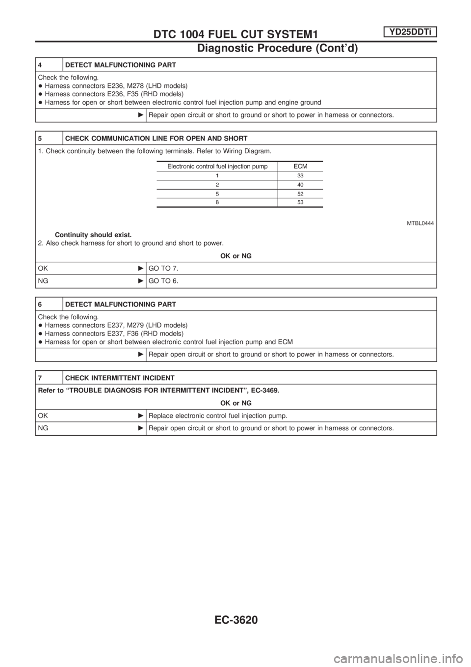
5 CHECK COMMUNICATION LINE FOR OPEN AND SHORT
1. Check continuity between the following terminals. Refer to Wiring Diagram.
MTBL0444
Continuity should exist.
2. Also check harness for short to ground and short to power.
OK or NG
OKcGO TO 7.
NGcGO TO 6.
6 DETECT MALFUNCTIONING PART
Check the following.
+Harness connectors E237, M279 (LHD models)
+Harness connectors E237, F36 (RHD models)
+Harness for open or short between electronic control fuel injection pump and ECM
cRepair open circuit or short to ground or short to power in harness or connectors.
7 CHECK INTERMITTENT INCIDENT
Refer to ªTROUBLE DIAGNOSIS FOR INTERMITTENT INCIDENTº, EC-3469.
OK or NG
OKcReplace electronic control fuel injection pump.
NGcRepair open circuit or short to ground or short to power in harness or connectors.
DTC 1004 FUEL CUT SYSTEM1YD25DDTi
Diagnostic Procedure (Cont'd)
EC-3620
Page 649 of 1306
Diagnostic Procedure
1 INSPECTION START
Check fuel level, fuel supplying system, starter motor, etc.
OK or NG
OKcGO TO 2.
NGcCorrect.
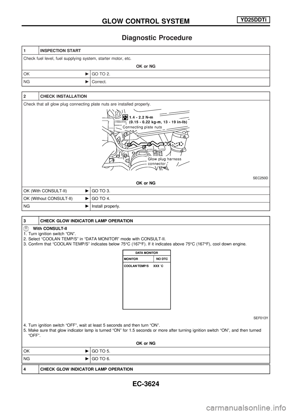
2 CHECK INSTALLATION
Check that all glow plug connecting plate nuts are installed properly.
SEC250D
OK or NG
OK (With CONSULT-II)cGO TO 3.
OK (Without CONSULT-II)cGO TO 4.
NGcInstall properly.
3 CHECK GLOW INDICATOR LAMP OPERATION
With CONSULT-II
1. Turn ignition switch ªONº.
2. Select ªCOOLAN TEMP/Sº in ªDATA MONITORº mode with CONSULT-II.
3. Confirm that ªCOOLAN TEMP/Sº indicates below 75ÉC (167ÉF). If it indicates above 75ÉC (167ÉF), cool down engine.
SEF013Y
4. Turn ignition switch ªOFFº, wait at least 5 seconds and then turn ªONº.
5. Make sure that glow indicator lamp is turned ªONº for 1.5 seconds or more after turning ignition switch ªONº, and then turned
ªOFFº.
OK or NG
OKcGO TO 5.
NGcGO TO 6.
4 CHECK GLOW INDICATOR LAMP OPERATION
GLOW CONTROL SYSTEMYD25DDTi
EC-3624
Page 650 of 1306
Without CONSULT-II
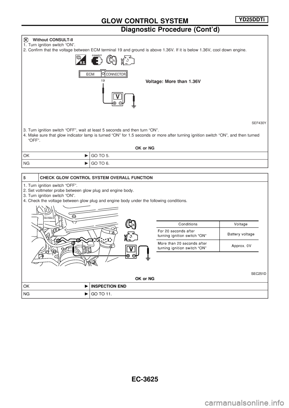
1. Turn ignition switch ªONº.
2. Confirm that the voltage between ECM terminal 19 and ground is above 1.36V. If it is below 1.36V, cool down engine.
SEF430Y
3. Turn ignition switch ªOFFº, wait at least 5 seconds and then turn ªONº.
4. Make sure that glow indicator lamp is turned ªONº for 1.5 seconds or more after turning ignition switch ªONº, and then turned
ªOFFº.
OK or NG
OKcGO TO 5.
NGcGO TO 6.
5 CHECK GLOW CONTROL SYSTEM OVERALL FUNCTION
1. Turn ignition switch ªOFFº.
2. Set voltmeter probe between glow plug and engine body.
3. Turn ignition switch ªONº.
4. Check the voltage between glow plug and engine body under the following conditions.
SEC251D
OK or NG
OKcINSPECTION END
NGcGO TO 11.
GLOW CONTROL SYSTEMYD25DDTi
Diagnostic Procedure (Cont'd)
EC-3625
Page 677 of 1306

METER AND GAUGES....................................... 3056
System Description .......................................... 3056
Combination Meter/With Tachometer .............. 3057
Combination Meter/Without Tachometer ......... 3058
Schematic/With Tachometer ............................ 3059
Schematic/Without Tachometer ....................... 3060
Construction ..................................................... 3061
Wiring Diagram - METER -/Gasoline Engine
with Tachometer .............................................. 3062
Wiring Diagram - METER -/Gasoline Engine
without Tachometer ......................................... 3064
Wiring Diagram - METER -/LHD Diesel Engine
Models with Tachometer.................................. 3065
Wiring Diagram - METER -/RHD Diesel
Engine Models with Tachometer ..................... 3067
Wiring Diagram - METER -/Diesel Engine
without Tachometer ......................................... 3069
Meter/Gauge Operation and Odo/Trip Meter
Segment Check in Diagnosis Mode ................ 3070
Trouble Diagnoses/With Tachometer .............. 3071
Trouble Diagnoses/Without Tachometer ......... 3076
WARNING LAMPS.............................................. 3081
Schematic/With Tachometer ............................ 3081
Schematic/Without Tachometer ....................... 3082
Wiring Diagram - WARN -/Gasoline Engine
with Tachometer .............................................. 3083
Wiring Diagram - WARN -/Gasoline Engine
without Tachometer ......................................... 3087
Wiring Diagram - WARN -/Diesel Engine with
Tachometer ...................................................... 3091
Wiring Diagram - WARN -/Diesel Engine
without Tachometer ......................................... 3095
A/T INDICATOR................................................... 3100
Wiring Diagram - AT/IND -/RHD Models ......... 3100
Wiring Diagram - CHIME -/LHD Models.......... 3101
Wiring Diagram - CHIME -/RHD Models ......... 3102
FRONT WIPER AND WASHER.......................... 3103
Wiring Diagram - WIPER -/Without Intermittent
for Floor-shift .................................................... 3103
Wiring Diagram - WIPER -/Without Intermittent
for RHD Column-shift Models .......................... 3106
HEADLAMP WASHER........................................ 3108
Wiring Diagram - HLC - ................................... 3108
HORN................................................................... 3109
Wiring Diagram - HORN -................................ 3109
CIGARETTE LIGHTER........................................ 3110
Wiring Diagram - CIGAR - ............................... 3110
CLOCK................................................................. 3111
Wiring Diagram - CLOCK - .............................. 3111
REAR WINDOW DEFOGGER AND MIRROR
DEFOGGER......................................................... 3112
Wiring Diagram - DEF - ................................... 3112
AUDIO.................................................................. 3113
Wiring Diagram - AUDIO -/LHD Models .......... 3113Wiring Diagram - AUDIO -/RHD Models ......... 3114
AUDIO ANTENNA............................................... 3115
Power Antenna/Wiring Diagram - P/ANT - ...... 3115
POWER DOOR MIRROR.................................... 3116
Wiring Diagram - MIRROR -/LHD Models....... 3116
Wiring Diagram - MIRROR -/RHD Models ...... 3117
HEATED SEAT.................................................... 3118
Wiring Diagram - H/SEAT - ............................. 3118
POWER WINDOW............................................... 3120
Schematic/Without Interruption Detection
Function ........................................................... 3120
Schematic/With Interruption Detection
Function ........................................................... 3121
Wiring Diagram - WINDOW -/Without
Interruption Detection Function........................ 3122
Wiring Diagram - WINDOW -/With Interruption
Detection Function ........................................... 3126
Trouble Diagnoses/Without Interruption
Detection Function ........................................... 3130
Trouble Diagnoses/With Interruption Detection
Function ........................................................... 3131
POWER DOOR LOCK......................................... 3133
Wiring Diagram - D/LOCK - ............................. 3133
MULTI-REMOTE CONTROL SYSTEM............... 3135
System Description .......................................... 3135
MULTI-REMOTE CONTROL SYSTEM............... 3136
Wiring Diagram - MULTI - ............................... 3136
Trouble Diagnoses ........................................... 3137
ID Code Entry Procedure ................................ 3139
Remote Controller Battery Replacement ......... 3140
THEFT WARNING SYSTEM............................... 3141
Wiring Diagram - PRWIRE - ............................ 3141
NATS (Nissan Anti-Theft System).................... 3142
Component Parts and Harness Connector
Location............................................................ 3142
System Description .......................................... 3143
System Composition ........................................ 3144
Wiring Diagram - NATS -/LHD Models............ 3145
Wiring Diagram - NATS -/RHD Diesel Engine
Models.............................................................. 3146
CONSULT-II ..................................................... 3147
Trouble Diagnoses ........................................... 3149
How to Replace NATS IMMU .......................... 3160
LOCATION OF ELECTRICAL UNITS................. 3161
Engine Compartment ....................................... 3161
Passenger Compartment ................................. 3162
HARNESS LAYOUT............................................ 3164
Main Harness ................................................... 3164
Engine Room Harness..................................... 3174
Engine Control Harness/KA engine ................. 3182
Engine Control Harness................................... 3184
Engine Harness ............................................... 3185
Alternator Harness ........................................... 3187
Instrument Harness.......................................... 3189
EL-3002