2001 NISSAN PICK-UP check engine
[x] Cancel search: check enginePage 889 of 1306
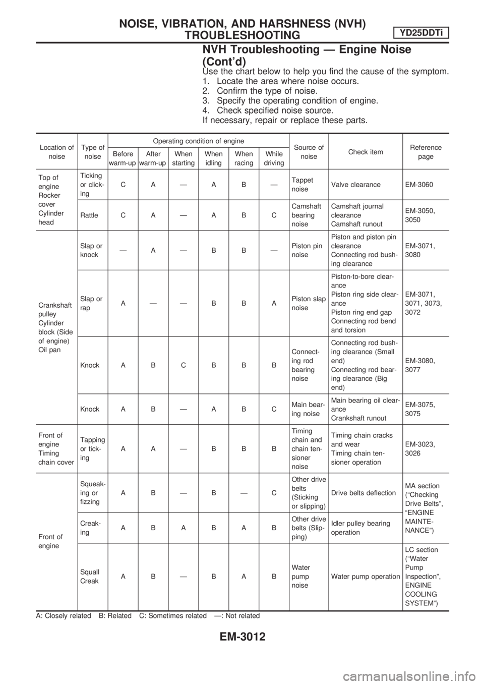
Use the chart below to help you find the cause of the symptom.
1. Locate the area where noise occurs.
2. Confirm the type of noise.
3. Specify the operating condition of engine.
4. Check specified noise source.
If necessary, repair or replace these parts.
Location of
noiseType of
noiseOperating condition of engine
Source of
noiseCheck itemReference
page Before
warm-upAfter
warm-upWhen
startingWhen
idlingWhen
racingWhile
driving
Top of
engine
Rocker
cover
Cylinder
headTicking
or click-
ingCAÐABÐTappet
noiseValve clearance EM-3060
Rattle C A Ð A B CCamshaft
bearing
noiseCamshaft journal
clearance
Camshaft runoutEM-3050,
3050
Crankshaft
pulley
Cylinder
block (Side
of engine)
Oil panSlap or
knockÐAÐB BÐPiston pin
noisePiston and piston pin
clearance
Connecting rod bush-
ing clearanceEM-3071,
3080
Slap or
rapAÐÐBBAPiston slap
noisePiston-to-bore clear-
ance
Piston ring side clear-
ance
Piston ring end gap
Connecting rod bend
and torsionEM-3071,
3071, 3073,
3072
Knock A B C B B BConnect-
ing rod
bearing
noiseConnecting rod bush-
ing clearance (Small
end)
Connecting rod bear-
ing clearance (Big
end)EM-3080,
3077
Knock A B Ð A B CMain bear-
ing noiseMain bearing oil clear-
ance
Crankshaft runoutEM-3075,
3075
Front of
engine
Timing
chain coverTapping
or tick-
ingAAÐBBBTiming
chain and
chain ten-
sioner
noiseTiming chain cracks
and wear
Timing chain ten-
sioner operationEM-3023,
3026
Front of
engineSqueak-
ing or
fizzingABÐBÐCOther drive
belts
(Sticking
or slipping)Drive belts deflectionMA section
(ªChecking
Drive Beltsº,
ªENGINE
MAINTE-
NANCEº) Creak-
ingABABABOther drive
belts (Slip-
ping)Idler pulley bearing
operation
Squall
CreakABÐBABWater
pump
noiseWater pump operationLC section
(ªWater
Pump
Inspectionº,
ENGINE
COOLING
SYSTEMº)
A: Closely related B: Related C: Sometimes related Ð: Not related
NOISE, VIBRATION, AND HARSHNESS (NVH)
TROUBLESHOOTINGYD25DDTi
NVH Troubleshooting Ð Engine Noise
(Cont'd)
EM-3012
Page 890 of 1306
1. Warm up engine.
2. Turn ignition switch OFF.
3. Using CONSULT-II, make sure no error codes are indicated
for self-diagnosis items. Refer to ªTrouble Diagnosis Ð
INDEXº in EC section.
+Do not disconnect CONSULT-II until the end of this opera-
tion; it will be used to check engine rpm and for error detec-
tion at the end of this operation.
4. Disconnect the negative battery terminal.
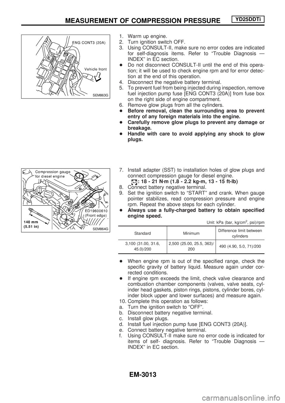
5. To prevent fuel from being injected during inspection, remove
fuel injection pump fuse [ENG CONT3 (20A)] from fuse box
on the right side of engine compartment.
6. Remove glow plugs from all the cylinders.
+Before removal, clean the surrounding area to prevent
entry of any foreign materials into the engine.
+Carefully remove glow plugs to prevent any damage or
breakage.
+Handle with care to avoid applying any shock to glow
plugs.
7. Install adapter (SST) to installation holes of glow plugs and
connect compression gauge for diesel engine.
:18-21Nzm (1.8 - 2.2 kg-m, 13 - 15 ft-lb)
8. Connect battery negative terminal.
9. Set the ignition switch to ªSTARTº and crank. When gauge
pointer stabilizes, read compression pressure and engine
rpm. Repeat the above steps for each cylinder.
+Always use a fully-charged battery to obtain specified
engine speed.
Unit: kPa (bar, kg/cm2, psi)/rpm
Standard MinimumDifference limit between
cylinders
3,100 (31.00, 31.6,
45.0)/2002,500 (25.00, 25.5, 363)/
200490 (4.90, 5.0, 71)/200
+When engine rpm is out of the specified range, check the
specific gravity of battery liquid. Measure again under cor-
rected conditions.
+If engine rpm exceeds the limit, check valve clearance and
combustion chamber components (valves, valve seats, cyl-
inder head gaskets, piston rings, pistons, cylinder bores, cyl-
inder block upper and lower surfaces) and measure again.
10. Complete this operation as follows:
a. Turn the ignition switch to ªOFFº.
b. Disconnect battery negative terminal.
c. Install glow plugs.
d. Install fuel injection pump fuse [ENG CONT3 (20A)].
e. Connect battery negative terminal.
f. Using CONSULT-II make sure no error code is indicated for
items of self- diagnosis. Refer to ªTrouble Diagnosis Ð
INDEXº in EC section.
SEM863G
SEM864G
MEASUREMENT OF COMPRESSION PRESSUREYD25DDTi
EM-3013
Page 909 of 1306
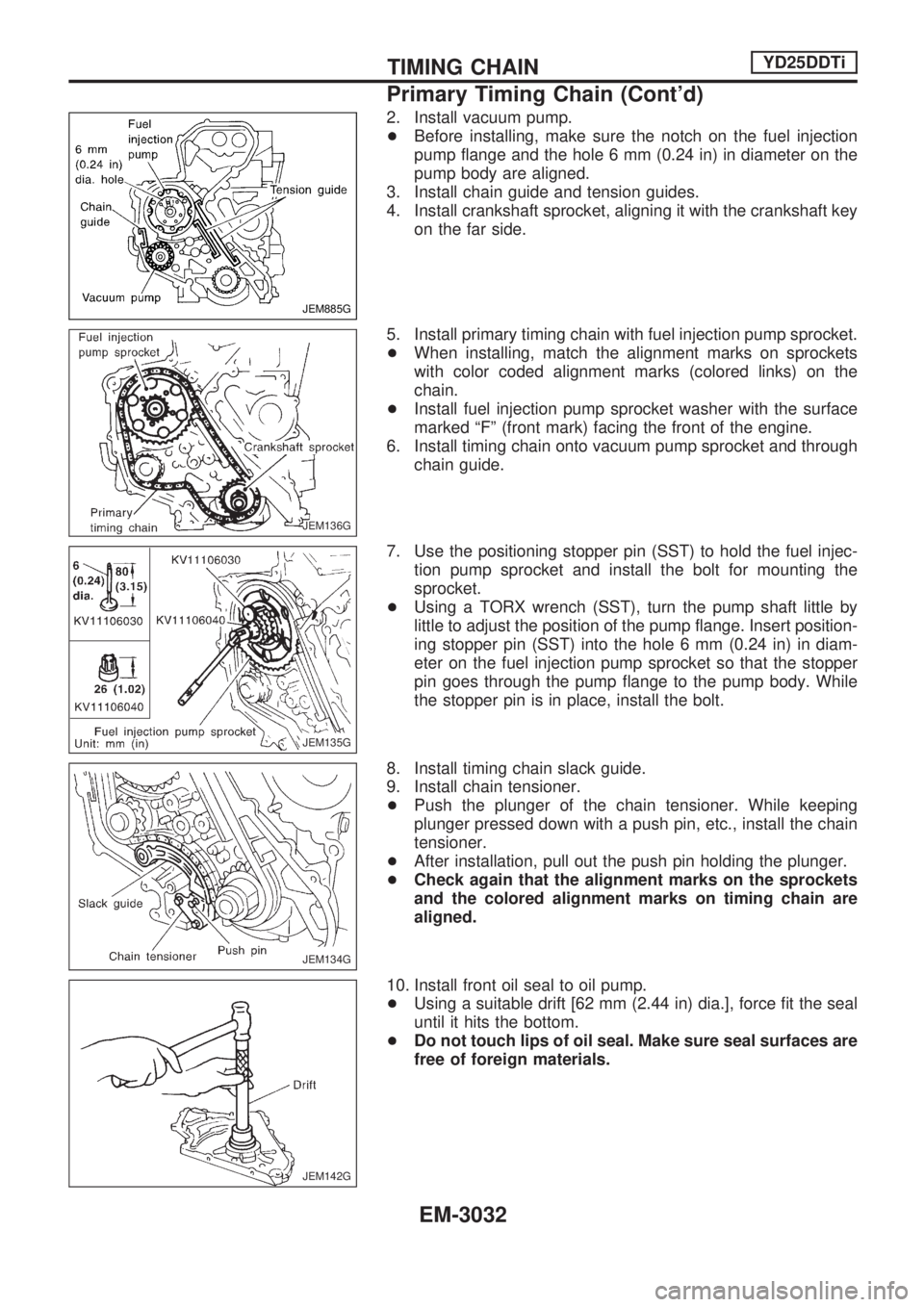
2. Install vacuum pump.
+Before installing, make sure the notch on the fuel injection
pump flange and the hole 6 mm (0.24 in) in diameter on the
pump body are aligned.
3. Install chain guide and tension guides.
4. Install crankshaft sprocket, aligning it with the crankshaft key
on the far side.
5. Install primary timing chain with fuel injection pump sprocket.
+When installing, match the alignment marks on sprockets
with color coded alignment marks (colored links) on the
chain.
+Install fuel injection pump sprocket washer with the surface
marked ªFº (front mark) facing the front of the engine.
6. Install timing chain onto vacuum pump sprocket and through
chain guide.
7. Use the positioning stopper pin (SST) to hold the fuel injec-
tion pump sprocket and install the bolt for mounting the
sprocket.
+Using a TORX wrench (SST), turn the pump shaft little by
little to adjust the position of the pump flange. Insert position-
ing stopper pin (SST) into the hole 6 mm (0.24 in) in diam-
eter on the fuel injection pump sprocket so that the stopper
pin goes through the pump flange to the pump body. While
the stopper pin is in place, install the bolt.
8. Install timing chain slack guide.
9. Install chain tensioner.
+Push the plunger of the chain tensioner. While keeping
plunger pressed down with a push pin, etc., install the chain
tensioner.
+After installation, pull out the push pin holding the plunger.
+Check again that the alignment marks on the sprockets
and the colored alignment marks on timing chain are
aligned.
10. Install front oil seal to oil pump.
+Using a suitable drift [62 mm (2.44 in) dia.], force fit the seal
until it hits the bottom.
+Do not touch lips of oil seal. Make sure seal surfaces are
free of foreign materials.
JEM885G
JEM136G
JEM135G
JEM134G
JEM142G
TIMING CHAINYD25DDTi
Primary Timing Chain (Cont'd)
EM-3032
Page 910 of 1306
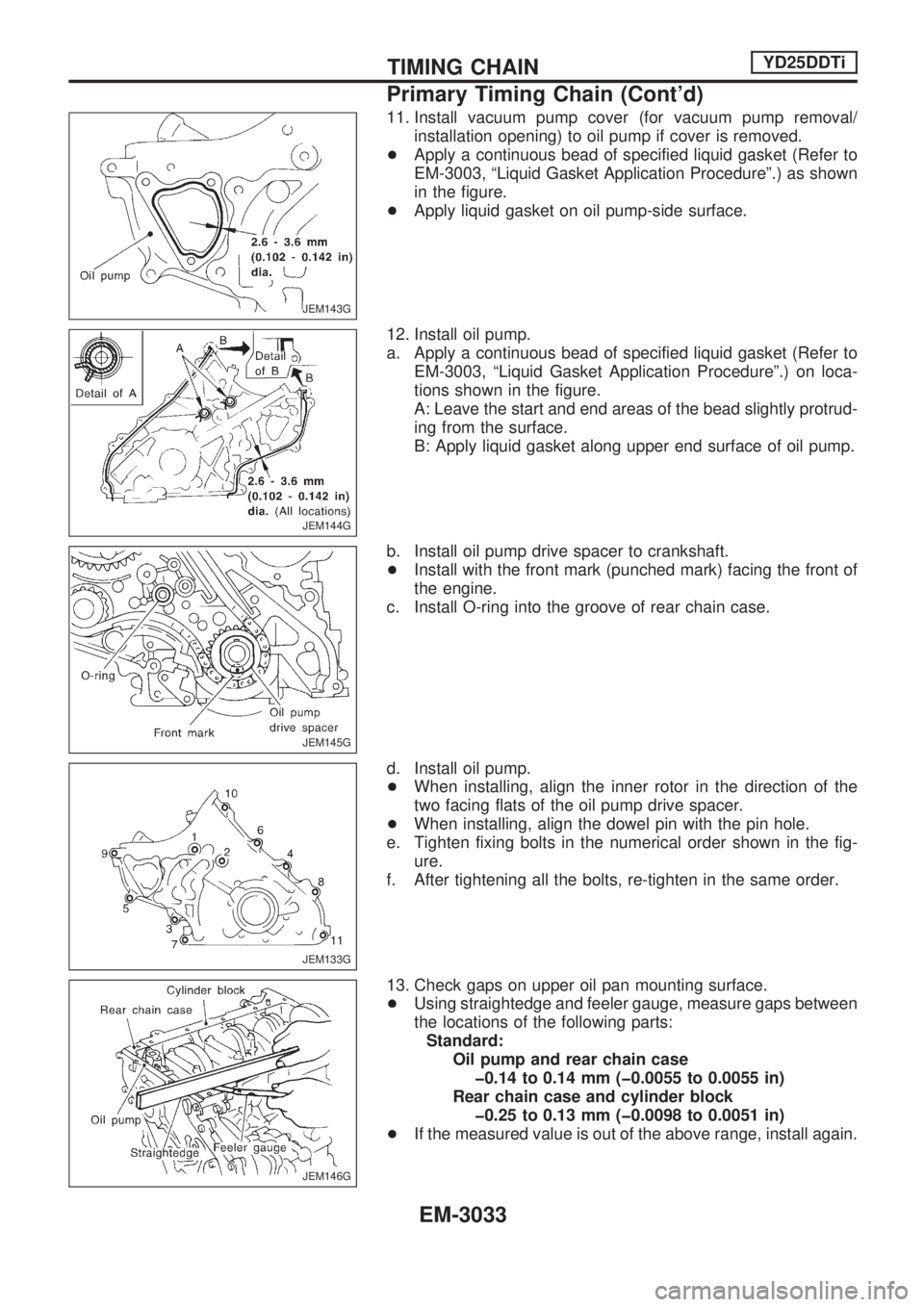
11. Install vacuum pump cover (for vacuum pump removal/
installation opening) to oil pump if cover is removed.
+Apply a continuous bead of specified liquid gasket (Refer to
EM-3003, ªLiquid Gasket Application Procedureº.) as shown
in the figure.
+Apply liquid gasket on oil pump-side surface.
12. Install oil pump.
a. Apply a continuous bead of specified liquid gasket (Refer to
EM-3003, ªLiquid Gasket Application Procedureº.) on loca-
tions shown in the figure.
A: Leave the start and end areas of the bead slightly protrud-
ing from the surface.
B: Apply liquid gasket along upper end surface of oil pump.
b. Install oil pump drive spacer to crankshaft.
+Install with the front mark (punched mark) facing the front of
the engine.
c. Install O-ring into the groove of rear chain case.
d. Install oil pump.
+When installing, align the inner rotor in the direction of the
two facing flats of the oil pump drive spacer.
+When installing, align the dowel pin with the pin hole.
e. Tighten fixing bolts in the numerical order shown in the fig-
ure.
f. After tightening all the bolts, re-tighten in the same order.
13. Check gaps on upper oil pan mounting surface.
+Using straightedge and feeler gauge, measure gaps between
the locations of the following parts:
Standard:
Oil pump and rear chain case
þ0.14 to 0.14 mm (þ0.0055 to 0.0055 in)
Rear chain case and cylinder block
þ0.25 to 0.13 mm (þ0.0098 to 0.0051 in)
+If the measured value is out of the above range, install again.
JEM143G
JEM144G
JEM145G
JEM133G
JEM146G
TIMING CHAINYD25DDTi
Primary Timing Chain (Cont'd)
EM-3033
Page 913 of 1306
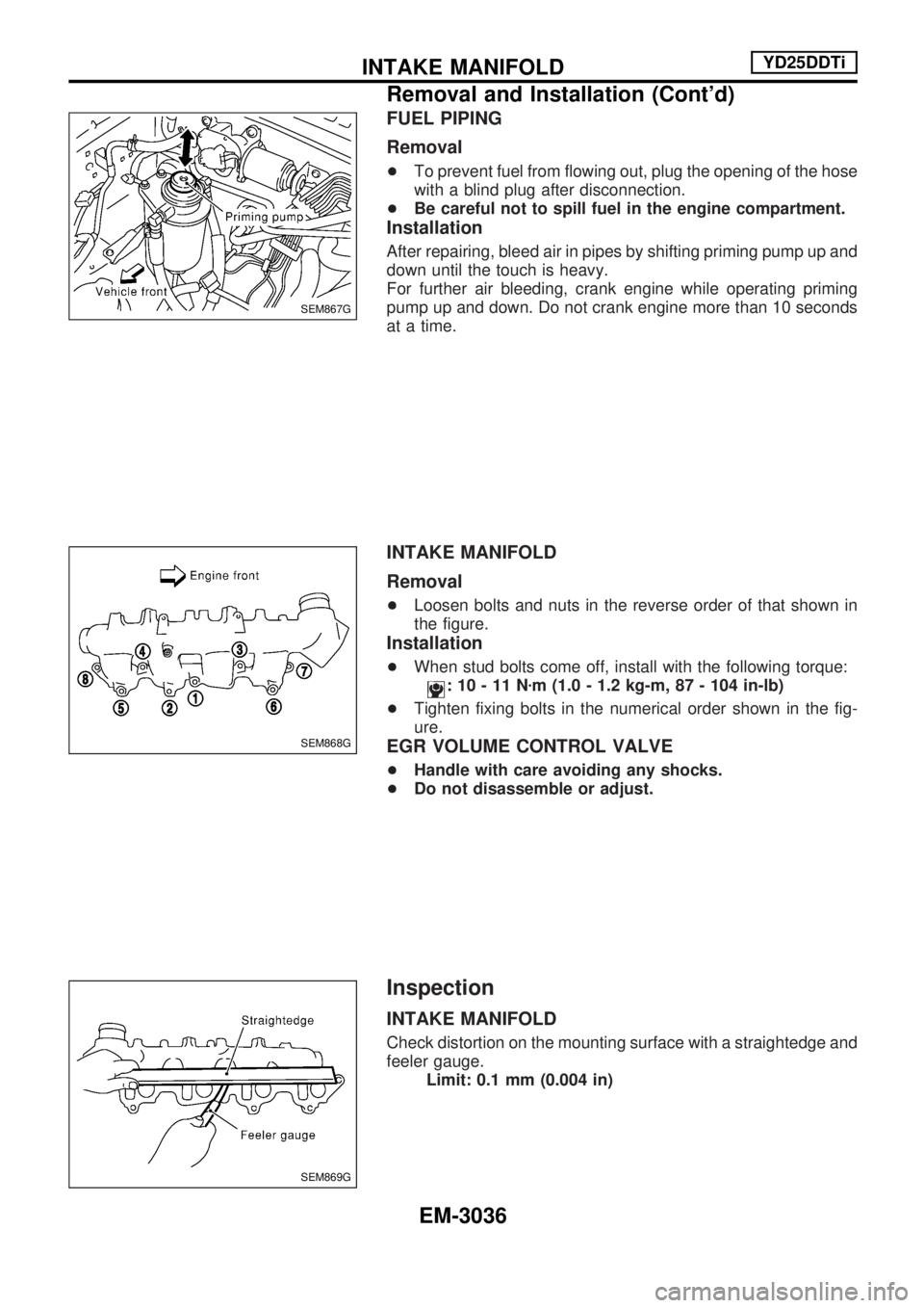
FUEL PIPING
Removal
+To prevent fuel from flowing out, plug the opening of the hose
with a blind plug after disconnection.
+Be careful not to spill fuel in the engine compartment.
Installation
After repairing, bleed air in pipes by shifting priming pump up and
down until the touch is heavy.
For further air bleeding, crank engine while operating priming
pump up and down. Do not crank engine more than 10 seconds
at a time.
INTAKE MANIFOLD
Removal
+Loosen bolts and nuts in the reverse order of that shown in
the figure.
Installation
+When stud bolts come off, install with the following torque:
:10-11Nzm (1.0 - 1.2 kg-m, 87 - 104 in-lb)
+Tighten fixing bolts in the numerical order shown in the fig-
ure.
EGR VOLUME CONTROL VALVE
+Handle with care avoiding any shocks.
+Do not disassemble or adjust.
Inspection
INTAKE MANIFOLD
Check distortion on the mounting surface with a straightedge and
feeler gauge.
Limit: 0.1 mm (0.004 in)
SEM867G
SEM868G
SEM869G
INTAKE MANIFOLDYD25DDTi
Removal and Installation (Cont'd)
EM-3036
Page 921 of 1306
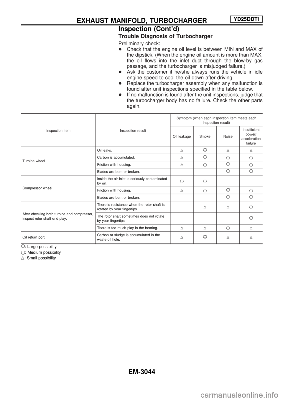
Trouble Diagnosis of Turbocharger
Preliminary check:
+Check that the engine oil level is between MIN and MAX of
the dipstick. (When the engine oil amount is more than MAX,
the oil flows into the inlet duct through the blow-by gas
passage, and the turbocharger is misjudged failure.)
+Ask the customer if he/she always runs the vehicle in idle
engine speed to cool the oil down after driving.
+Replace the turbocharger assembly when any malfunction is
found after unit inspections specified in the table below.
+If no malfunction is found after the unit inspections, judge that
the turbocharger body has no failure. Check the other parts
again.
Inspection item Inspection resultSymptom (when each inspection item meets each
inspection result)
Oil leakage Smoke NoiseInsufficient
power/
acceleration
failure
Turbine wheelOil leaks.n
nn
Carbon is accumulated.n
jj
Friction with housing.nj
j
Blades are bent or broken.
Compressor wheelInside the air inlet is seriously contaminated
by oil.jj
Friction with housing.njj
Blades are bent or broken.
After checking both turbine and compressor,
inspect rotor shaft end play.There is resistance when the rotor shaft is
rotated by your fingertips.nnj
The rotor shaft sometimes does not rotate
by your fingertips.
There is too much play in the bearing.nnjn
Oil return portCarbon or sludge is accumulated in the
waste oil hole.n
nn
: Large possibility
j: Medium possibility
n: Small possibility
EXHAUST MANIFOLD, TURBOCHARGERYD25DDTi
Inspection (Cont'd)
EM-3044
Page 935 of 1306
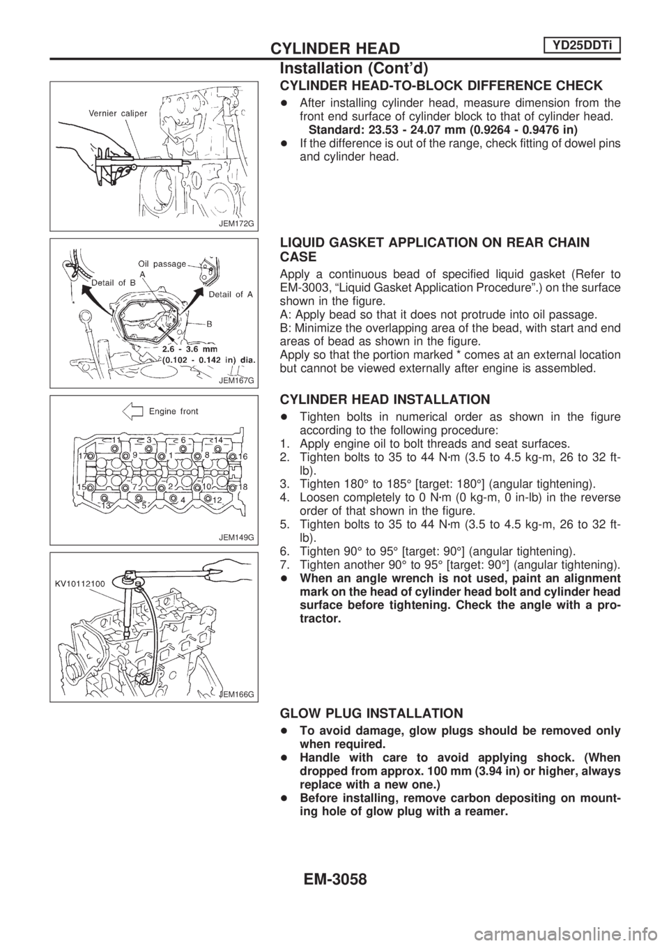
CYLINDER HEAD-TO-BLOCK DIFFERENCE CHECK
+After installing cylinder head, measure dimension from the
front end surface of cylinder block to that of cylinder head.
Standard: 23.53 - 24.07 mm (0.9264 - 0.9476 in)
+If the difference is out of the range, check fitting of dowel pins
and cylinder head.
LIQUID GASKET APPLICATION ON REAR CHAIN
CASE
Apply a continuous bead of specified liquid gasket (Refer to
EM-3003, ªLiquid Gasket Application Procedureº.) on the surface
shown in the figure.
A: Apply bead so that it does not protrude into oil passage.
B: Minimize the overlapping area of the bead, with start and end
areas of bead as shown in the figure.
Apply so that the portion marked * comes at an external location
but cannot be viewed externally after engine is assembled.
CYLINDER HEAD INSTALLATION
+Tighten bolts in numerical order as shown in the figure
according to the following procedure:
1. Apply engine oil to bolt threads and seat surfaces.
2. Tighten bolts to 35 to 44 Nzm (3.5 to 4.5 kg-m, 26 to 32 ft-
lb).
3. Tighten 180É to 185É [target: 180É] (angular tightening).
4. Loosen completely to 0 Nzm (0 kg-m, 0 in-lb) in the reverse
order of that shown in the figure.
5. Tighten bolts to 35 to 44 Nzm (3.5 to 4.5 kg-m, 26 to 32 ft-
lb).
6. Tighten 90É to 95É [target: 90É] (angular tightening).
7. Tighten another 90É to 95É [target: 90É] (angular tightening).
+When an angle wrench is not used, paint an alignment
mark on the head of cylinder head bolt and cylinder head
surface before tightening. Check the angle with a pro-
tractor.
GLOW PLUG INSTALLATION
+To avoid damage, glow plugs should be removed only
when required.
+Handle with care to avoid applying shock. (When
dropped from approx. 100 mm (3.94 in) or higher, always
replace with a new one.)
+Before installing, remove carbon depositing on mount-
ing hole of glow plug with a reamer.
JEM172G
JEM167G
JEM149G
JEM166G
CYLINDER HEADYD25DDTi
Installation (Cont'd)
EM-3058
Page 937 of 1306
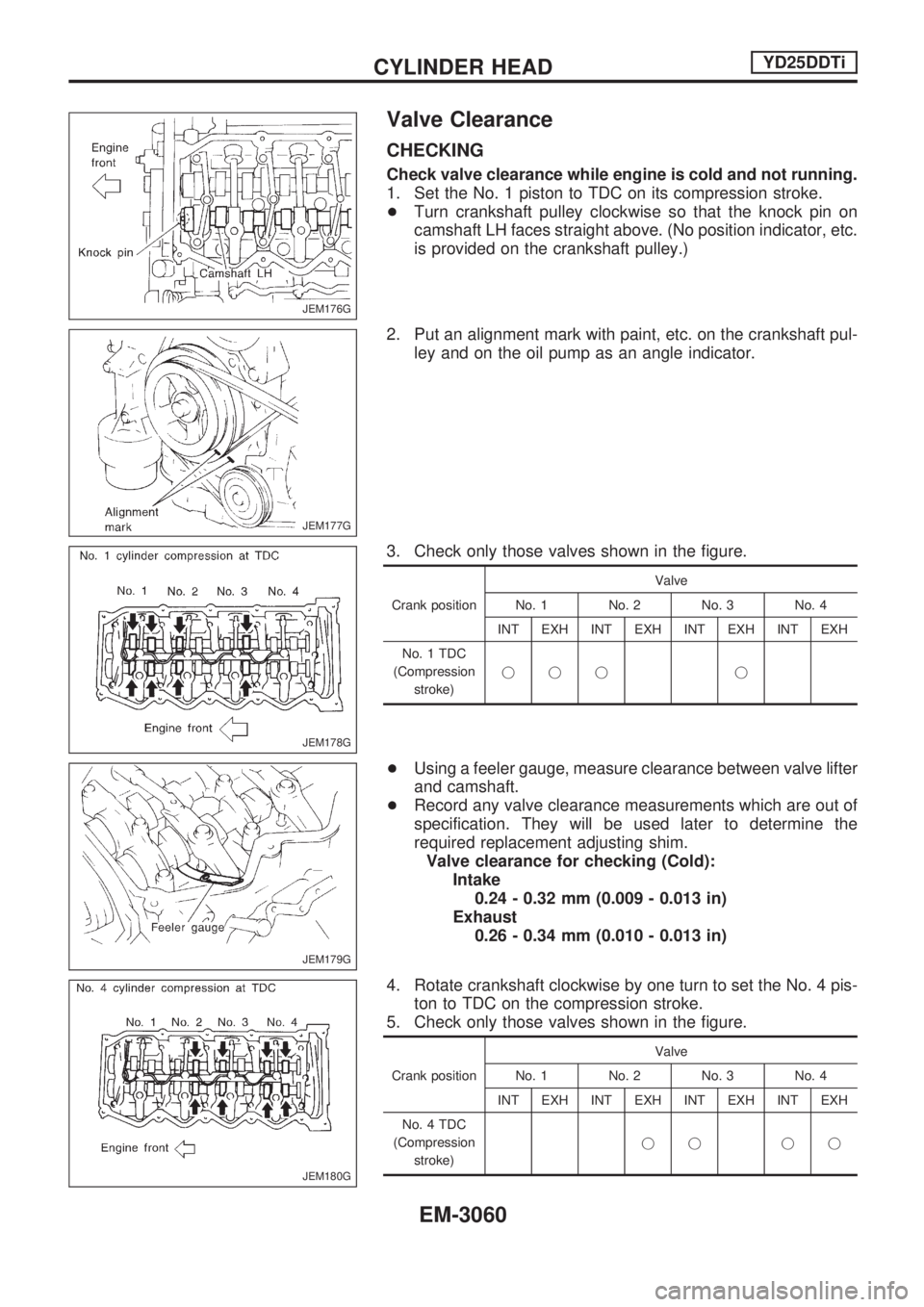
Valve Clearance
CHECKING
Check valve clearance while engine is cold and not running.
1. Set the No. 1 piston to TDC on its compression stroke.
+Turn crankshaft pulley clockwise so that the knock pin on
camshaft LH faces straight above. (No position indicator, etc.
is provided on the crankshaft pulley.)
2. Put an alignment mark with paint, etc. on the crankshaft pul-
ley and on the oil pump as an angle indicator.
3. Check only those valves shown in the figure.
Crank positionValve
No. 1 No. 2 No. 3 No. 4
INT EXH INT EXH INT EXH INT EXH
No. 1 TDC
(Compression
stroke)jjj j
+Using a feeler gauge, measure clearance between valve lifter
and camshaft.
+Record any valve clearance measurements which are out of
specification. They will be used later to determine the
required replacement adjusting shim.
Valve clearance for checking (Cold):
Intake
0.24 - 0.32 mm (0.009 - 0.013 in)
Exhaust
0.26 - 0.34 mm (0.010 - 0.013 in)
4. Rotate crankshaft clockwise by one turn to set the No. 4 pis-
ton to TDC on the compression stroke.
5. Check only those valves shown in the figure.
Crank positionValve
No. 1 No. 2 No. 3 No. 4
INT EXH INT EXH INT EXH INT EXH
No. 4 TDC
(Compression
stroke)jj jj
JEM176G
JEM177G
JEM178G
JEM179G
JEM180G
CYLINDER HEADYD25DDTi
EM-3060