Page 1046 of 1306

Oil Pressure Check
WARNING:
+Be careful not to burn yourself, as the engine and oil
may be hot.
+Oil pressure check should be done in ªNeutral positionº.
1. Check oil level.
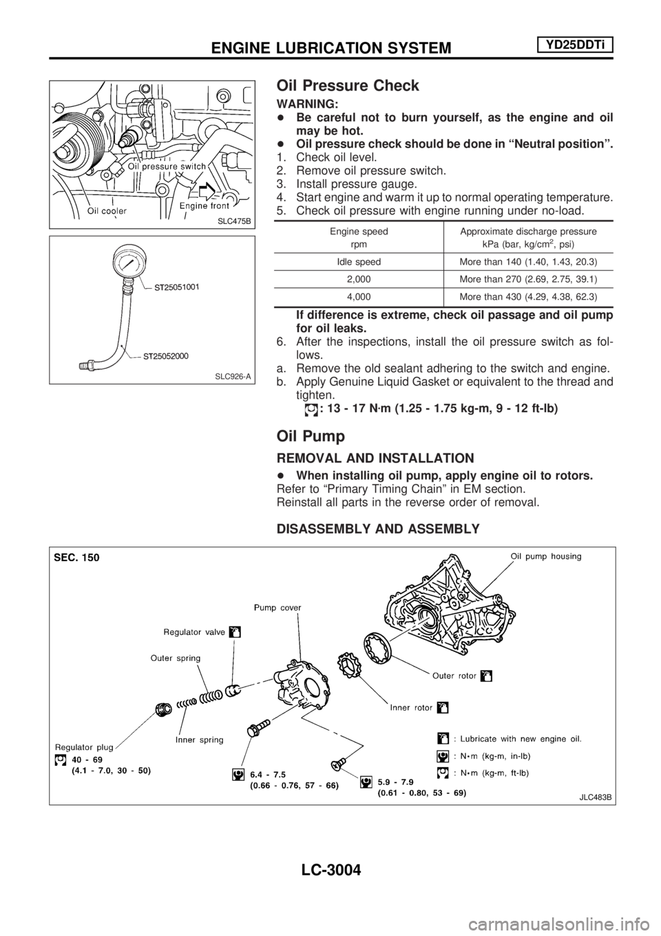
2. Remove oil pressure switch.
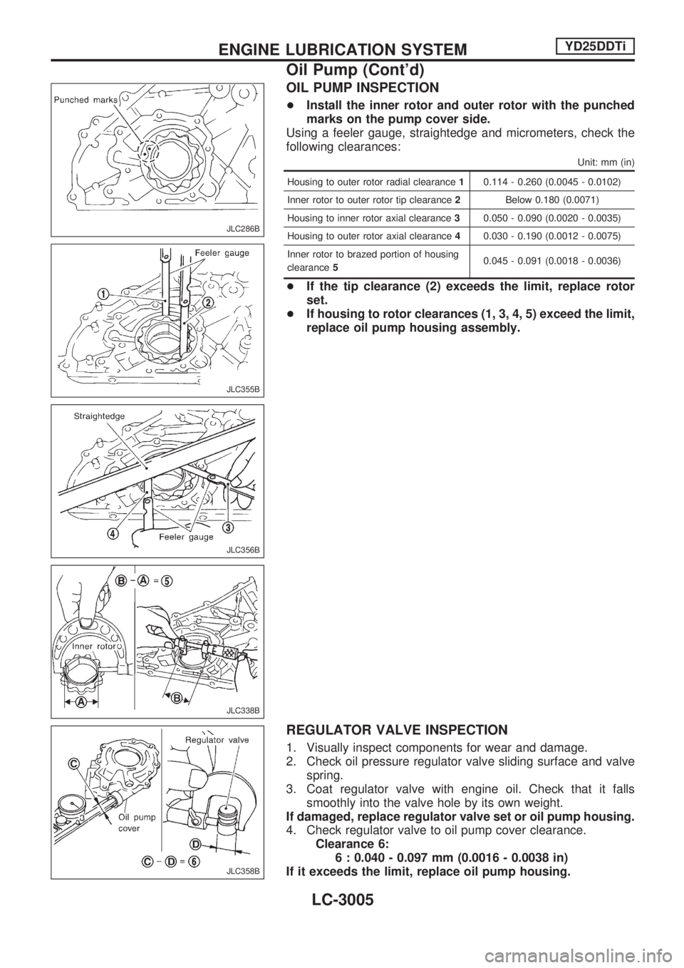
3. Install pressure gauge.
4. Start engine and warm it up to normal operating temperature.
5. Check oil pressure with engine running under no-load.
Engine speed
rpmApproximate discharge pressure
kPa (bar, kg/cm2, psi)
Idle speed More than 140 (1.40, 1.43, 20.3)
2,000 More than 270 (2.69, 2.75, 39.1)
4,000 More than 430 (4.29, 4.38, 62.3)
If difference is extreme, check oil passage and oil pump
for oil leaks.
6. After the inspections, install the oil pressure switch as fol-
lows.
a. Remove the old sealant adhering to the switch and engine.
b. Apply Genuine Liquid Gasket or equivalent to the thread and
tighten.
:13-17Nzm (1.25 - 1.75 kg-m,9-12ft-lb)
Oil Pump
REMOVAL AND INSTALLATION
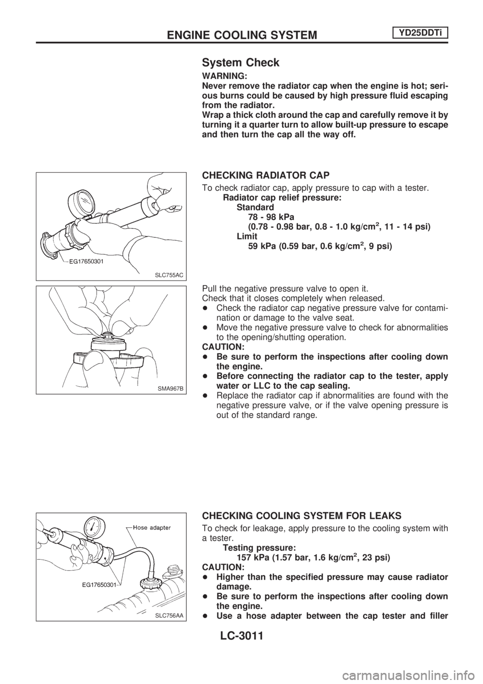
+When installing oil pump, apply engine oil to rotors.
Refer to ªPrimary Timing Chainº in EM section.
Reinstall all parts in the reverse order of removal.
DISASSEMBLY AND ASSEMBLY
SLC475B
SLC926-A
JLC483B
ENGINE LUBRICATION SYSTEMYD25DDTi
LC-3004
Page 1047 of 1306

OIL PUMP INSPECTION
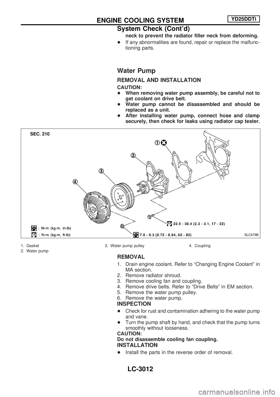
+Install the inner rotor and outer rotor with the punched
marks on the pump cover side.
Using a feeler gauge, straightedge and micrometers, check the
following clearances:
Unit: mm (in)
Housing to outer rotor radial clearance10.114 - 0.260 (0.0045 - 0.0102)
Inner rotor to outer rotor tip clearance2Below 0.180 (0.0071)
Housing to inner rotor axial clearance30.050 - 0.090 (0.0020 - 0.0035)
Housing to outer rotor axial clearance40.030 - 0.190 (0.0012 - 0.0075)
Inner rotor to brazed portion of housing
clearance50.045 - 0.091 (0.0018 - 0.0036)
+If the tip clearance (2) exceeds the limit, replace rotor
set.
+If housing to rotor clearances (1, 3, 4, 5) exceed the limit,
replace oil pump housing assembly.
REGULATOR VALVE INSPECTION
1. Visually inspect components for wear and damage.
2. Check oil pressure regulator valve sliding surface and valve
spring.
3. Coat regulator valve with engine oil. Check that it falls
smoothly into the valve hole by its own weight.
If damaged, replace regulator valve set or oil pump housing.
4. Check regulator valve to oil pump cover clearance.
Clearance 6:
6 : 0.040 - 0.097 mm (0.0016 - 0.0038 in)
If it exceeds the limit, replace oil pump housing.
JLC286B
JLC355B
JLC356B
JLC338B
JLC358B
ENGINE LUBRICATION SYSTEMYD25DDTi
Oil Pump (Cont'd)
LC-3005
Page 1050 of 1306
Overheating Cause Analysis
TROUBLESHOOTING CHART
Symptom Check items
Cooling system parts
malfunctionPoor heat transferWater pump malfunction Worn or loose drive belt
Ð Thermostat stuck closed Ð
Damaged finsDust contamination or
paper clogging
Mechanical damage
Clogged radiator cooling
tubeExcess foreign material
(rust, dirt, sand, etc.)
Reduced air flowCooling fan does not
operate
ÐÐ High resistance to fan
rotation
Damaged fan blades
Damaged radiator
shroudÐÐÐ
Improper coolant mixture
ratioÐÐÐ
Poor coolant quality Ð Ð Ð
Insufficient coolantCoolant leaksCooling hoseLoose clamp
Cracked hose
Water pump Poor sealing
Radiator capLoose
Poor sealing
RadiatorO-ring for damage, dete-
rioration or improper fit-
ting
Cracked radiator tank
Cracked radiator core
Reservoir tank Cracked reservoir tank
Overflowing reservoir
tankExhaust gas leaks into
cooling systemCylinder head deteriora-
tion
Cylinder head gasket
deterioration
ENGINE COOLING SYSTEMYD25DDTi
LC-3008
Page 1051 of 1306
Symptom Check items
Except cooling system
parts malfunctionÐ Overload on engineAbusive drivingHigh engine rpm under
no load
Driving in low gear for
extended time
Driving at extremely high
speed
Power train system mal-
function
Ð Installed improper size
wheels and tires
Dragging brakes
Improper ignition timing
Blocked or restricted air
flowBlocked bumper Ð
Ð Blocked radiator grilleInstalled car brassiere
Mud contamination or
paper clogging
Blocked radiator Ð
Blocked condenser
Ð
Installed large fog lamp
ENGINE COOLING SYSTEMYD25DDTi
Overheating Cause Analysis (Cont'd)
LC-3009
Page 1053 of 1306

System Check
WARNING:
Never remove the radiator cap when the engine is hot; seri-
ous burns could be caused by high pressure fluid escaping
from the radiator.
Wrap a thick cloth around the cap and carefully remove it by
turning it a quarter turn to allow built-up pressure to escape
and then turn the cap all the way off.
CHECKING RADIATOR CAP
To check radiator cap, apply pressure to cap with a tester.
Radiator cap relief pressure:
Standard
78-98kPa
(0.78 - 0.98 bar, 0.8 - 1.0 kg/cm
2, 11 - 14 psi)
Limit
59 kPa (0.59 bar, 0.6 kg/cm
2, 9 psi)
Pull the negative pressure valve to open it.
Check that it closes completely when released.
+Check the radiator cap negative pressure valve for contami-
nation or damage to the valve seat.
+Move the negative pressure valve to check for abnormalities
to the opening/shutting operation.
CAUTION:
+Be sure to perform the inspections after cooling down
the engine.
+Before connecting the radiator cap to the tester, apply
water or LLC to the cap sealing.
+Replace the radiator cap if abnormalities are found with the
negative pressure valve, or if the valve opening pressure is
out of the standard range.
CHECKING COOLING SYSTEM FOR LEAKS
To check for leakage, apply pressure to the cooling system with
a tester.
Testing pressure:
157 kPa (1.57 bar, 1.6 kg/cm
2, 23 psi)
CAUTION:
+Higher than the specified pressure may cause radiator
damage.
+Be sure to perform the inspections after cooling down
the engine.
+Use a hose adapter between the cap tester and filler
SLC755AC
SMA967B
SLC756AA
ENGINE COOLING SYSTEMYD25DDTi
LC-3011
Page 1054 of 1306

neck to prevent the radiator filler neck from deforming.
+If any abnormalities are found, repair or replace the malfunc-
tioning parts.
Water Pump
REMOVAL AND INSTALLATION
CAUTION:
+When removing water pump assembly, be careful not to
get coolant on drive belt.
+Water pump cannot be disassembled and should be
replaced as a unit.
+After installing water pump, connect hose and clamp
securely, then check for leaks using radiator cap tester.
1. Gasket
2. Water pump3. Water pump pulley 4. Coupling
REMOVAL
1. Drain engine coolant. Refer to ªChanging Engine Coolantº in
MA section.
2. Remove radiator shroud.
3. Remove cooling fan and coupling.
4. Remove drive belts. Refer to ªDrive Beltsº in EM section.
5. Remove the water pump pulley.
6. Remove the water pump.
INSPECTION
+Check for rust and contamination adhering to the water pump
and vane.
+Turn the pump shaft by hand, and check that the pump turns
smoothly without looseness.
CAUTION:
Do not disassemble cooling fan coupling.
INSTALLATION
+Install the parts in the reverse order of removal.
SLC479B
ENGINE COOLING SYSTEMYD25DDTi
System Check (Cont'd)
LC-3012
Page 1056 of 1306
Thermostat and Water Piping
REMOVAL AND INSTALLATION
+Be careful not to spill coolant over engine compartment.
Use a rag to absorb coolant.
1. Drain engine coolant. Refer to ªChanging Engine Coolantº in
MA section.
2. Remove water inlet.
3. Remove thermostat.
4. Install thermostat with jiggle valve facing upward.
+Carefully install the rubber ring to the flange of the
thermostat, making sure it does not slip out of place.
5. After installation and refilling coolant, run engine for a few
minutes, and check for leaks.
SLC480B
JLC300B
ENGINE COOLING SYSTEMYD25DDTi
LC-3014
Page 1057 of 1306
INSPECTION
1. Check valve seating condition at ordinary room tempera-
tures. It should seat tightly.
2. Check valve opening temperature and maximum valve lift.
Standard
Valve opening temperature Above 80 - 84ÉC (176 - 183ÉF)
Valve lift More than 10 mm/95ÉC
(0.39 in/203ÉF)
3. Then check if valve closes at 5ÉC (9ÉF) below valve opening
temperature.
Radiator
REMOVAL AND INSTALLATION
1. Remove under guard.
2. Drain engine coolant. Refer to MA section, ªChanging Engine
Coolantº.
3. Remove radiator shroud (lower).
4. Remove radiator shroud (upper).
5. Disconnect radiator hose (upper and lower).
6. Disconnect reservoir tank hose.
7. Remove radiator.
8. After repairing or replacing radiator, install all removed parts
in reverse order of removal.
SLC252B
SLC481B
ENGINE COOLING SYSTEMYD25DDTi
Thermostat and Water Piping (Cont'd)
LC-3015