2001 NISSAN PICK-UP check engine
[x] Cancel search: check enginePage 1060 of 1306
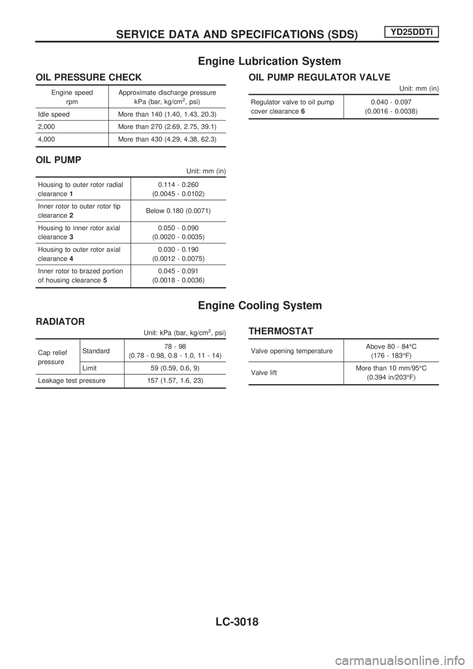
Engine Lubrication System
OIL PRESSURE CHECK
Engine speed
rpmApproximate discharge pressure
kPa (bar, kg/cm2, psi)
Idle speed More than 140 (1.40, 1.43, 20.3)
2,000 More than 270 (2.69, 2.75, 39.1)
4,000 More than 430 (4.29, 4.38, 62.3)
OIL PUMP
Unit: mm (in)
Housing to outer rotor radial
clearance10.114 - 0.260
(0.0045 - 0.0102)
Inner rotor to outer rotor tip
clearance2Below 0.180 (0.0071)
Housing to inner rotor axial
clearance30.050 - 0.090
(0.0020 - 0.0035)
Housing to outer rotor axial
clearance40.030 - 0.190
(0.0012 - 0.0075)
Inner rotor to brazed portion
of housing clearance50.045 - 0.091
(0.0018 - 0.0036)
OIL PUMP REGULATOR VALVE
Unit: mm (in)
Regulator valve to oil pump
cover clearance60.040 - 0.097
(0.0016 - 0.0038)
Engine Cooling System
RADIATOR
Unit: kPa (bar, kg/cm2, psi)
Cap relief
pressureStandard78-98
(0.78 - 0.98, 0.8 - 1.0, 11 - 14)
Limit 59 (0.59, 0.6, 9)
Leakage test pressure 157 (1.57, 1.6, 23)
THERMOSTAT
Valve opening temperatureAbove 80 - 84ÉC
(176 - 183ÉF)
Valve liftMore than 10 mm/95ÉC
(0.394 in/203ÉF)
SERVICE DATA AND SPECIFICATIONS (SDS)YD25DDTi
LC-3018
Page 1063 of 1306
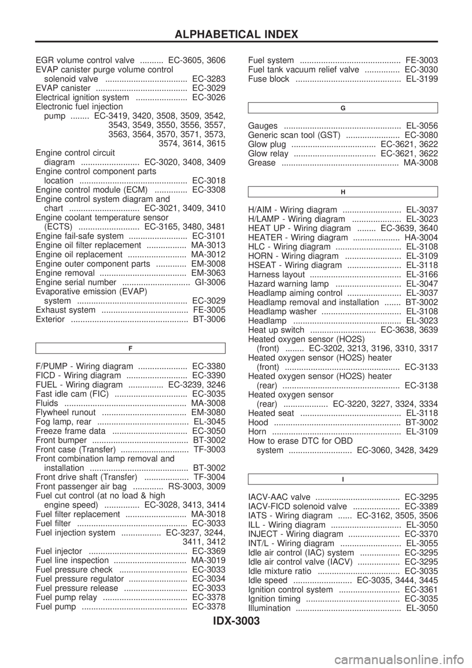
EGR volume control valve .......... EC-3605, 3606
EVAP canister purge volume control
solenoid valve ................................... EC-3283
EVAP canister ....................................... EC-3029
Electrical ignition system ...................... EC-3026
Electronic fuel injection
pump ........ EC-3419, 3420, 3508, 3509, 3542,
3543, 3549, 3550, 3556, 3557,
3563, 3564, 3570, 3571, 3573,
3574, 3614, 3615
Engine control circuit
diagram ......................... EC-3020, 3408, 3409
Engine control component parts
location .............................................. EC-3018
Engine control module (ECM) .............. EC-3308
Engine control system diagram and
chart .............................. EC-3021, 3409, 3410
Engine coolant temperature sensor
(ECTS) .......................... EC-3165, 3480, 3481
Engine fail-safe system ......................... EC-3101
Engine oil filter replacement ................. MA-3013
Engine oil replacement ......................... MA-3012
Engine outer component parts ............. EM-3008
Engine removal ..................................... EM-3063
Engine serial number ............................. GI-3006
Evaporative emission (EVAP)
system ............................................... EC-3029
Exhaust system ..................................... FE-3005
Exterior .................................................. BT-3006
F
F/PUMP - Wiring diagram ..................... EC-3380
FICD - Wiring diagram .......................... EC-3390
FUEL - Wiring diagram ............... EC-3239, 3246
Fast idle cam (FIC) ............................... EC-3035
Fluids .................................................... MA-3008
Flywheel runout .................................... EM-3080
Fog lamp, rear ....................................... EL-3045
Freeze frame data ................................ EC-3050
Front bumper ......................................... BT-3002
Front case (Transfer) ............................. TF-3003
Front combination lamp removal and
installation .......................................... BT-3002
Front drive shaft (Transfer) ................... TF-3004
Front passenger air bag ............. RS-3003, 3009
Fuel cut control (at no load & high
engine speed) ............... EC-3028, 3413, 3414
Fuel filter replacement .......................... MA-3018
Fuel filter ............................................... EC-3033
Fuel injection system ................. EC-3237, 3244,
3411, 3412
Fuel injector .......................................... EC-3369
Fuel line inspection ............................... MA-3019
Fuel pressure check ............................. EC-3033
Fuel pressure regulator ......................... EC-3034
Fuel pressure release ........................... EC-3033
Fuel pump relay .................................... EC-3378
Fuel pump ............................................. EC-3378Fuel system ........................................... FE-3003
Fuel tank vacuum relief valve ............... EC-3030
Fuse block ............................................. EL-3199
G
Gauges .................................................. EL-3056
Generic scan tool (GST) ....................... EC-3080
Glow plug .................................... EC-3621, 3622
Glow relay ................................... EC-3621, 3622
Grease .................................................. MA-3008
H
H/AIM - Wiring diagram ......................... EL-3037
H/LAMP - Wiring diagram ..................... EL-3023
HEAT UP - Wiring diagram ........ EC-3639, 3640
HEATER - Wiring diagram .................... HA-3004
HLC - Wiring diagram ............................ EL-3108
HORN - Wiring diagram ........................ EL-3109
HSEAT - Wiring diagram ....................... EL-3118
Harness layout ....................................... EL-3166
Hazard warning lamp ............................ EL-3047
Headlamp aiming control ....................... EL-3037
Headlamp removal and installation ....... BT-3002
Headlamp washer .................................. EL-3108
Headlamp .............................................. EL-3023
Heat up switch ............................ EC-3638, 3639
Heated oxygen sensor (HO2S)
(front) ........ EC-3202, 3213, 3196, 3310, 3317
Heated oxygen sensor (HO2S) heater
(front) ................................................. EC-3133
Heated oxygen sensor (HO2S) heater
(rear) .................................................. EC-3138
Heated oxygen sensor
(rear) ................... EC-3220, 3227, 3324, 3334
Heated seat ........................................... EL-3118
Hood ...................................................... BT-3002
Horn ....................................................... EL-3109
How to erase DTC for OBD
system ........................... EC-3060, 3428, 3429
I
IACV-AAC valve .................................... EC-3295
IACV-FICD solenoid valve .................... EC-3389
IATS - Wiring diagram ...... EC-3162, 3505, 3506
ILL - Wiring diagram .............................. EL-3050
INJECT - Wiring diagram ...................... EC-3370
INT/L - Wiring diagram .......................... EL-3055
Idle air control (IAC) system ................. EC-3295
Idle air control valve (IACV) .................. EC-3295
Idle mixture ratio ................................... EC-3035
Idle speed ......................... EC-3035, 3444, 3445
Ignition control system .......................... EC-3361
Ignition timing ........................................ EC-3035
Illumination ............................................. EL-3050
ALPHABETICAL INDEX
IDX-3003
Page 1113 of 1306
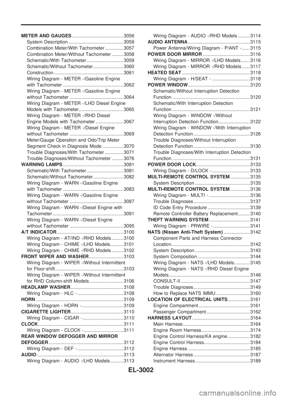
METER AND GAUGES....................................... 3056
System Description .......................................... 3056
Combination Meter/With Tachometer .............. 3057
Combination Meter/Without Tachometer ......... 3058
Schematic/With Tachometer ............................ 3059
Schematic/Without Tachometer ....................... 3060
Construction ..................................................... 3061
Wiring Diagram - METER -/Gasoline Engine
with Tachometer .............................................. 3062
Wiring Diagram - METER -/Gasoline Engine
without Tachometer ......................................... 3064
Wiring Diagram - METER -/LHD Diesel Engine
Models with Tachometer.................................. 3065
Wiring Diagram - METER -/RHD Diesel
Engine Models with Tachometer ..................... 3067
Wiring Diagram - METER -/Diesel Engine
without Tachometer ......................................... 3069
Meter/Gauge Operation and Odo/Trip Meter
Segment Check in Diagnosis Mode ................ 3070
Trouble Diagnoses/With Tachometer .............. 3071
Trouble Diagnoses/Without Tachometer ......... 3076
WARNING LAMPS.............................................. 3081
Schematic/With Tachometer ............................ 3081
Schematic/Without Tachometer ....................... 3082
Wiring Diagram - WARN -/Gasoline Engine
with Tachometer .............................................. 3083
Wiring Diagram - WARN -/Gasoline Engine
without Tachometer ......................................... 3087
Wiring Diagram - WARN -/Diesel Engine with
Tachometer ...................................................... 3091
Wiring Diagram - WARN -/Diesel Engine
without Tachometer ......................................... 3095
A/T INDICATOR................................................... 3100
Wiring Diagram - AT/IND -/RHD Models ......... 3100
Wiring Diagram - CHIME -/LHD Models.......... 3101
Wiring Diagram - CHIME -/RHD Models ......... 3102
FRONT WIPER AND WASHER.......................... 3103
Wiring Diagram - WIPER -/Without Intermittent
for Floor-shift .................................................... 3103
Wiring Diagram - WIPER -/Without Intermittent
for RHD Column-shift Models .......................... 3106
HEADLAMP WASHER........................................ 3108
Wiring Diagram - HLC - ................................... 3108
HORN................................................................... 3109
Wiring Diagram - HORN -................................ 3109
CIGARETTE LIGHTER........................................ 3110
Wiring Diagram - CIGAR - ............................... 3110
CLOCK................................................................. 3111
Wiring Diagram - CLOCK - .............................. 3111
REAR WINDOW DEFOGGER AND MIRROR
DEFOGGER......................................................... 3112
Wiring Diagram - DEF - ................................... 3112
AUDIO.................................................................. 3113
Wiring Diagram - AUDIO -/LHD Models .......... 3113Wiring Diagram - AUDIO -/RHD Models ......... 3114
AUDIO ANTENNA............................................... 3115
Power Antenna/Wiring Diagram - P/ANT - ...... 3115
POWER DOOR MIRROR.................................... 3116
Wiring Diagram - MIRROR -/LHD Models....... 3116
Wiring Diagram - MIRROR -/RHD Models ...... 3117
HEATED SEAT.................................................... 3118
Wiring Diagram - H/SEAT - ............................. 3118
POWER WINDOW............................................... 3120
Schematic/Without Interruption Detection
Function ........................................................... 3120
Schematic/With Interruption Detection
Function ........................................................... 3121
Wiring Diagram - WINDOW -/Without
Interruption Detection Function........................ 3122
Wiring Diagram - WINDOW -/With Interruption
Detection Function ........................................... 3126
Trouble Diagnoses/Without Interruption
Detection Function ........................................... 3130
Trouble Diagnoses/With Interruption Detection
Function ........................................................... 3131
POWER DOOR LOCK......................................... 3133
Wiring Diagram - D/LOCK - ............................. 3133
MULTI-REMOTE CONTROL SYSTEM............... 3135
System Description .......................................... 3135
MULTI-REMOTE CONTROL SYSTEM............... 3136
Wiring Diagram - MULTI - ............................... 3136
Trouble Diagnoses ........................................... 3137
ID Code Entry Procedure ................................ 3139
Remote Controller Battery Replacement ......... 3140
THEFT WARNING SYSTEM............................... 3141
Wiring Diagram - PRWIRE - ............................ 3141
NATS (Nissan Anti-Theft System).................... 3142
Component Parts and Harness Connector
Location............................................................ 3142
System Description .......................................... 3143
System Composition ........................................ 3144
Wiring Diagram - NATS -/LHD Models............ 3145
Wiring Diagram - NATS -/RHD Diesel Engine
Models.............................................................. 3146
CONSULT-II ..................................................... 3147
Trouble Diagnoses ........................................... 3149
How to Replace NATS IMMU .......................... 3160
LOCATION OF ELECTRICAL UNITS................. 3161
Engine Compartment ....................................... 3161
Passenger Compartment ................................. 3162
HARNESS LAYOUT............................................ 3164
Main Harness ................................................... 3164
Engine Room Harness..................................... 3174
Engine Control Harness/KA engine ................. 3182
Engine Control Harness................................... 3184
Engine Harness ............................................... 3185
Alternator Harness ........................................... 3187
Instrument Harness.......................................... 3189
EL-3002
Page 1184 of 1306
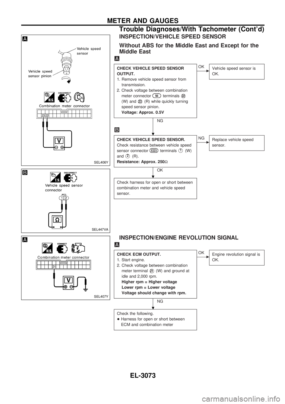
INSPECTION/VEHICLE SPEED SENSOR
Without ABS for the Middle East and Except for the
Middle East
CHECK VEHICLE SPEED SENSOR
OUTPUT.
1. Remove vehicle speed sensor from
transmission.
2. Check voltage between combination
meter connector
N4terminalsV22
(W) andV23(R) while quickly turning
speed sensor pinion.
Voltage: Approx. 0.5V
NG
cOK
Vehicle speed sensor is
OK.
CHECK VEHICLE SPEED SENSOR.
Check resistance between vehicle speed
sensor connector
E223terminalsV1(W)
and
V2(R).
Resistance: Approx. 250W
OK
cNG
Replace vehicle speed
sensor.
Check harness for open or short between
combination meter and vehicle speed
sensor.
INSPECTION/ENGINE REVOLUTION SIGNAL
CHECK ECM OUTPUT.
1. Start engine.
2. Check voltage between combination
meter terminal
V21(W) and ground at
idle and 2,000 rpm.
Higher rpm = Higher voltage
Lower rpm = Lower voltage
Voltage should change with rpm.
NG
cOK
Engine revolution signal is
OK.
Check the following.
+Harness for open or short between
ECM and combination meter
SEL406Y
SEL447VA
SEL407Y
.
.
.
METER AND GAUGES
Trouble Diagnoses/With Tachometer (Cont'd)
EL-3073
Page 1259 of 1306
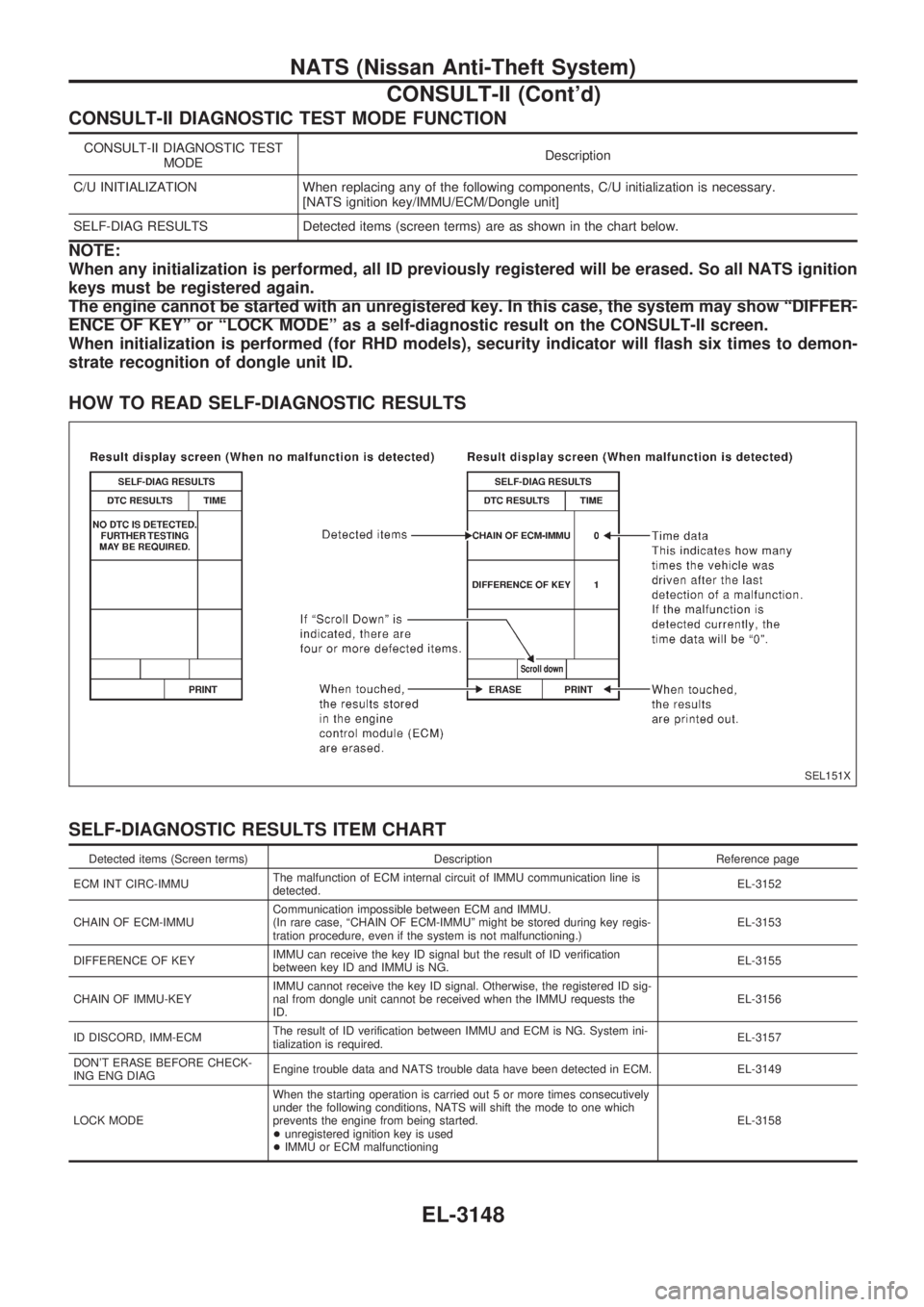
CONSULT-II DIAGNOSTIC TEST MODE FUNCTION
CONSULT-II DIAGNOSTIC TEST
MODEDescription
C/U INITIALIZATION When replacing any of the following components, C/U initialization is necessary.
[NATS ignition key/IMMU/ECM/Dongle unit]
SELF-DIAG RESULTS Detected items (screen terms) are as shown in the chart below.
NOTE:
When any initialization is performed, all ID previously registered will be erased. So all NATS ignition
keys must be registered again.
The engine cannot be started with an unregistered key. In this case, the system may show ªDIFFER-
ENCE OF KEYº or ªLOCK MODEº as a self-diagnostic result on the CONSULT-II screen.
When initialization is performed (for RHD models), security indicator will flash six times to demon-
strate recognition of dongle unit ID.
HOW TO READ SELF-DIAGNOSTIC RESULTS
SELF-DIAGNOSTIC RESULTS ITEM CHART
Detected items (Screen terms) Description Reference page
ECM INT CIRC-IMMUThe malfunction of ECM internal circuit of IMMU communication line is
detected.EL-3152
CHAIN OF ECM-IMMUCommunication impossible between ECM and IMMU.
(In rare case, ªCHAIN OF ECM-IMMUº might be stored during key regis-
tration procedure, even if the system is not malfunctioning.)EL-3153
DIFFERENCE OF KEYIMMU can receive the key ID signal but the result of ID verification
between key ID and IMMU is NG.EL-3155
CHAIN OF IMMU-KEYIMMU cannot receive the key ID signal. Otherwise, the registered ID sig-
nal from dongle unit cannot be received when the IMMU requests the
ID.EL-3156
ID DISCORD, IMM-ECMThe result of ID verification between IMMU and ECM is NG. System ini-
tialization is required.EL-3157
DON'T ERASE BEFORE CHECK-
ING ENG DIAGEngine trouble data and NATS trouble data have been detected in ECM. EL-3149
LOCK MODEWhen the starting operation is carried out 5 or more times consecutively
under the following conditions, NATS will shift the mode to one which
prevents the engine from being started.
+unregistered ignition key is used
+IMMU or ECM malfunctioningEL-3158
SEL151X
NATS (Nissan Anti-Theft System)
CONSULT-II (Cont'd)
EL-3148
Page 1260 of 1306
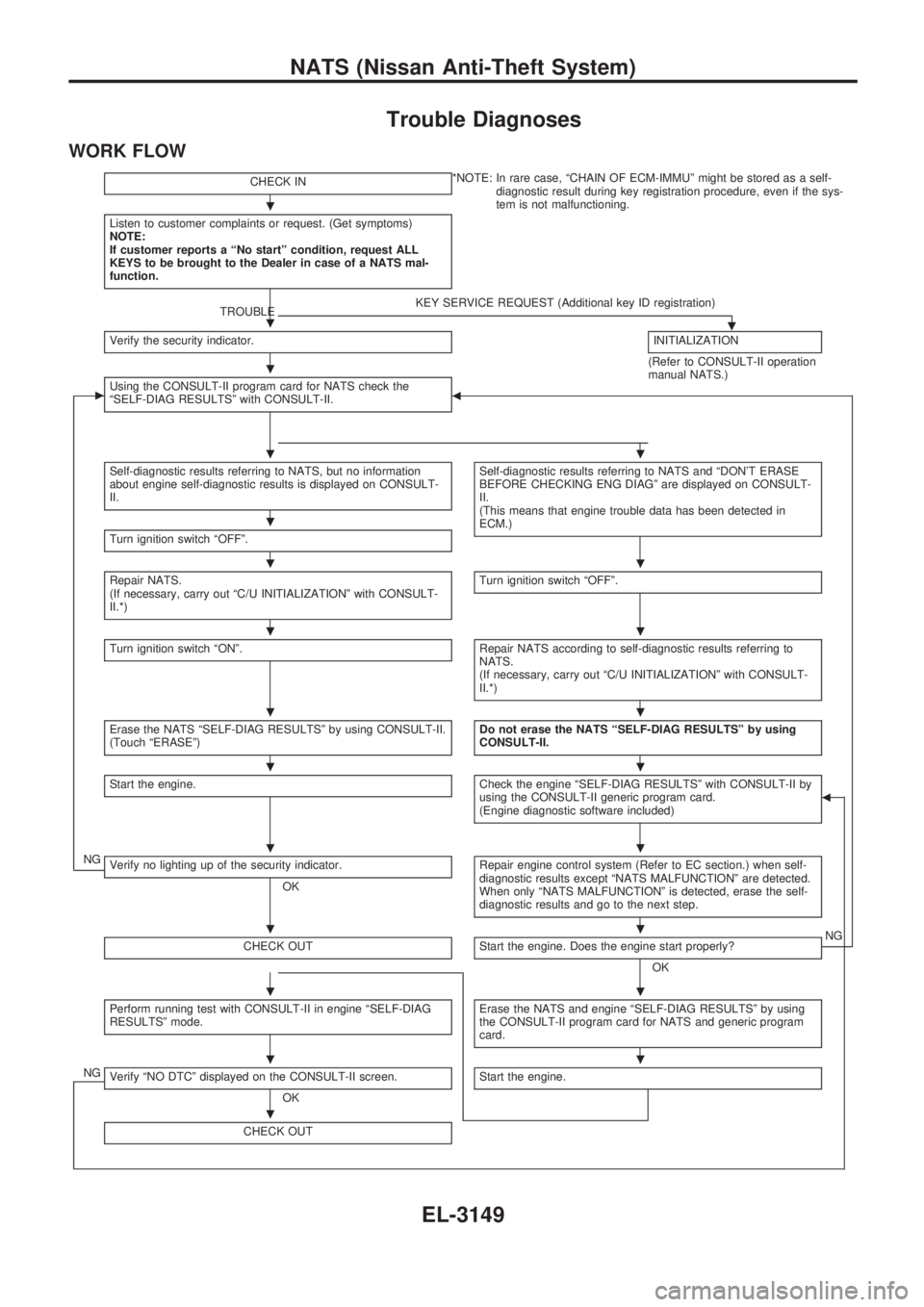
Trouble Diagnoses
WORK FLOW
CHECK IN*NOTE: In rare case, ªCHAIN OF ECM-IMMUº might be stored as a self-
diagnostic result during key registration procedure, even if the sys-
tem is not malfunctioning.
Listen to customer complaints or request. (Get symptoms)
NOTE:
If customer reports a ªNo startº condition, request ALL
KEYS to be brought to the Dealer in case of a NATS mal-
function.
TROUBLEKEY SERVICE REQUEST (Additional key ID registration).Verify the security indicator.INITIALIZATION
(Refer to CONSULT-II operation
manual NATS.)
cUsing the CONSULT-II program card for NATS check the
ªSELF-DIAG RESULTSº with CONSULT-II.b
Self-diagnostic results referring to NATS, but no information
about engine self-diagnostic results is displayed on CONSULT-
II.Self-diagnostic results referring to NATS and ªDON'T ERASE
BEFORE CHECKING ENG DIAGº are displayed on CONSULT-
II.
(This means that engine trouble data has been detected in
ECM.)
Turn ignition switch ªOFFº.
Repair NATS.
(If necessary, carry out ªC/U INITIALIZATIONº with CONSULT-
II.*)Turn ignition switch ªOFFº.
Turn ignition switch ªONº.Repair NATS according to self-diagnostic results referring to
NATS.
(If necessary, carry out ªC/U INITIALIZATIONº with CONSULT-
II.*)
Erase the NATS ªSELF-DIAG RESULTSº by using CONSULT-II.
(Touch ªERASEº)Do not erase the NATS ªSELF-DIAG RESULTSº by using
CONSULT-II.
Start the engine.Check the engine ªSELF-DIAG RESULTSº with CONSULT-II by
using the CONSULT-II generic program card.
(Engine diagnostic software included)b
NGVerify no lighting up of the security indicator.
OKRepair engine control system (Refer to EC section.) when self-
diagnostic results except ªNATS MALFUNCTIONº are detected.
When only ªNATS MALFUNCTIONº is detected, erase the self-
diagnostic results and go to the next step.
CHECK OUTStart the engine. Does the engine start properly?
OKNG
Perform running test with CONSULT-II in engine ªSELF-DIAG
RESULTSº mode.Erase the NATS and engine ªSELF-DIAG RESULTSº by using
the CONSULT-II program card for NATS and generic program
card.
NGVerify ªNO DTCº displayed on the CONSULT-II screen.
OKStart the engine.
CHECK OUT
.
.
.
..
.
..
..
..
..
..
..
..
..
.
NATS (Nissan Anti-Theft System)
EL-3149
Page 1264 of 1306
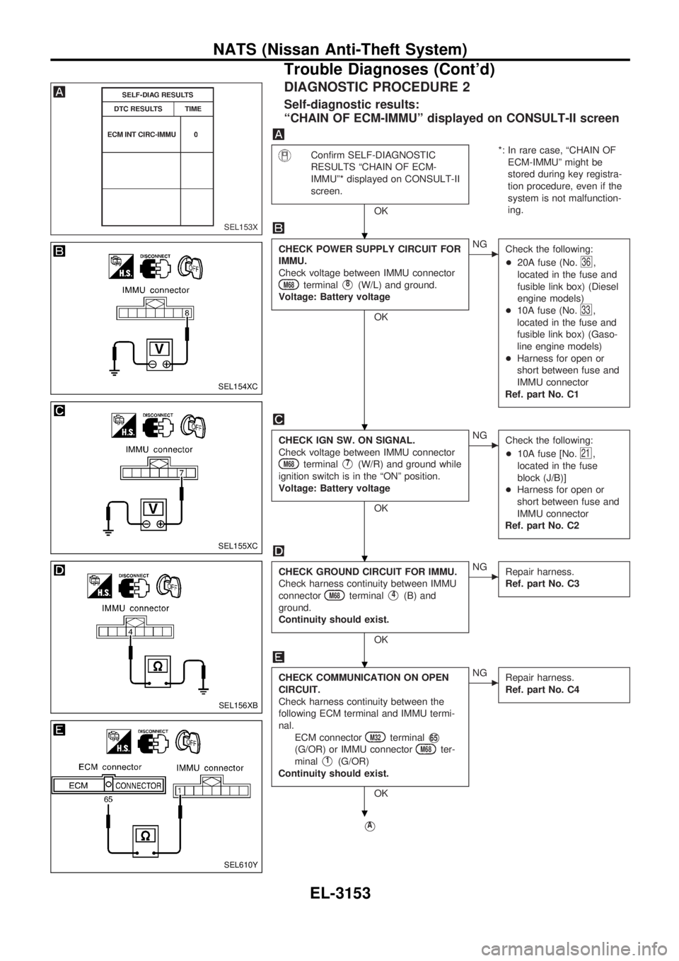
DIAGNOSTIC PROCEDURE 2
Self-diagnostic results:
ªCHAIN OF ECM-IMMUº displayed on CONSULT-II screen
Confirm SELF-DIAGNOSTIC
RESULTS ªCHAIN OF ECM-
IMMUº* displayed on CONSULT-II
screen.
OK*: In rare case, ªCHAIN OF
ECM-IMMUº might be
stored during key registra-
tion procedure, even if the
system is not malfunction-
ing.
CHECK POWER SUPPLY CIRCUIT FOR
IMMU.
Check voltage between IMMU connector
M68terminalV8(W/L) and ground.
Voltage: Battery voltage
OK
cNG
Check the following:
+20A fuse (No.
36,
located in the fuse and
fusible link box) (Diesel
engine models)
+10A fuse (No.
33,
located in the fuse and
fusible link box) (Gaso-
line engine models)
+Harness for open or
short between fuse and
IMMU connector
Ref. part No. C1
CHECK IGN SW. ON SIGNAL.
Check voltage between IMMU connector
M68terminalV7(W/R) and ground while
ignition switch is in the ªONº position.
Voltage: Battery voltage
OK
cNG
Check the following:
+10A fuse [No.
21,
located in the fuse
block (J/B)]
+Harness for open or
short between fuse and
IMMU connector
Ref. part No. C2
CHECK GROUND CIRCUIT FOR IMMU.
Check harness continuity between IMMU
connector
M68terminalV4(B) and
ground.
Continuity should exist.
OK
cNG
Repair harness.
Ref. part No. C3
CHECK COMMUNICATION ON OPEN
CIRCUIT.
Check harness continuity between the
following ECM terminal and IMMU termi-
nal.
ECM connector
M32terminalV65
(G/OR) or IMMU connectorM68ter-
minal
V1(G/OR)
Continuity should exist.
OK
cNG
Repair harness.
Ref. part No. C4
VA
SEL153X
SEL154XC
SEL155XC
SEL156XB
SEL610Y
.
.
.
.
.
NATS (Nissan Anti-Theft System)
Trouble Diagnoses (Cont'd)
EL-3153
Page 1267 of 1306
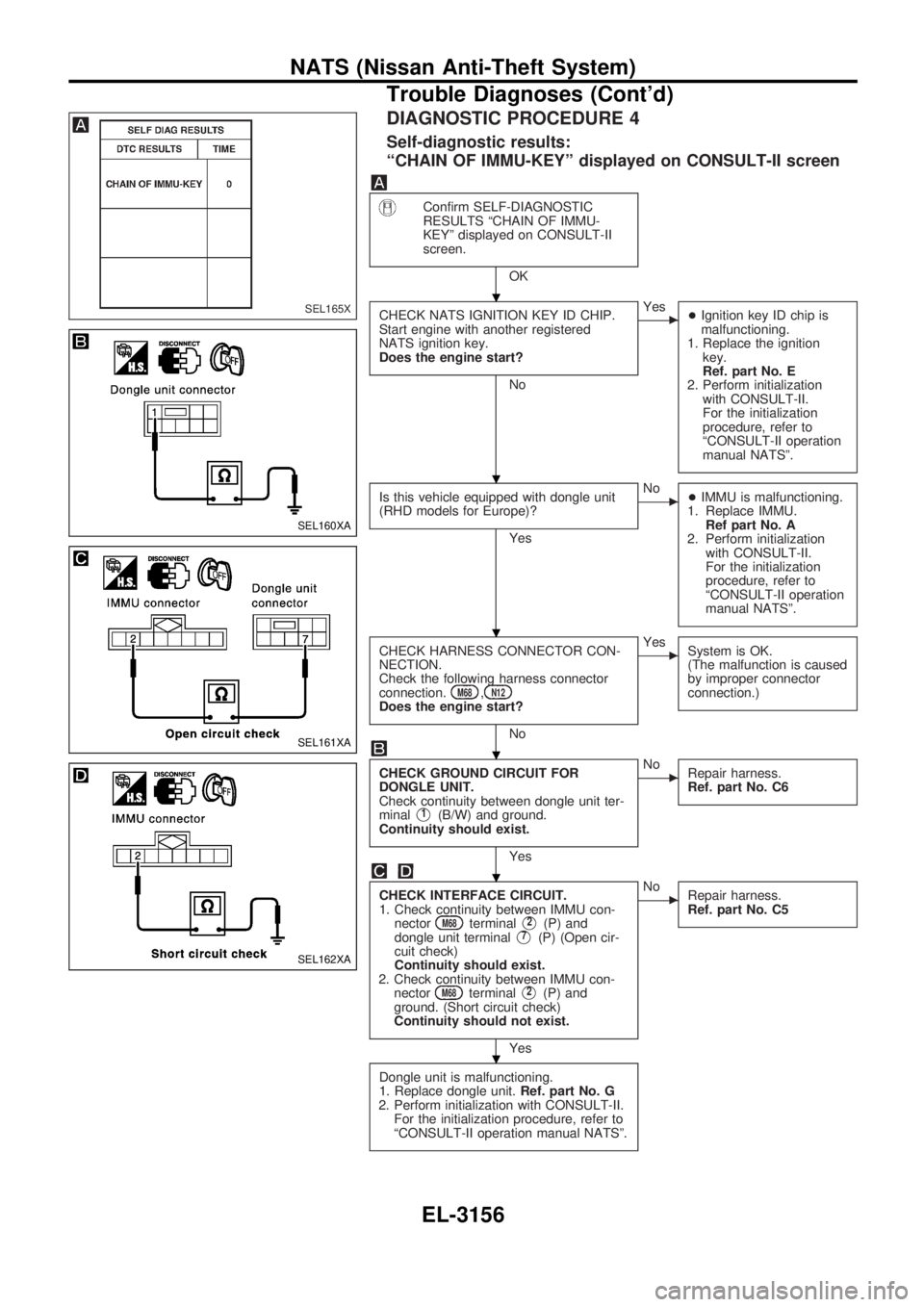
DIAGNOSTIC PROCEDURE 4
Self-diagnostic results:
ªCHAIN OF IMMU-KEYº displayed on CONSULT-II screen
Confirm SELF-DIAGNOSTIC
RESULTS ªCHAIN OF IMMU-
KEYº displayed on CONSULT-II
screen.
OK
CHECK NATS IGNITION KEY ID CHIP.
Start engine with another registered
NATS ignition key.
Does the engine start?
No
cYes
+Ignition key ID chip is
malfunctioning.
1. Replace the ignition
key.
Ref. part No. E
2. Perform initialization
with CONSULT-II.
For the initialization
procedure, refer to
ªCONSULT-II operation
manual NATSº.
Is this vehicle equipped with dongle unit
(RHD models for Europe)?
Yes
cNo
+IMMU is malfunctioning.
1. Replace IMMU.
Ref part No. A
2. Perform initialization
with CONSULT-II.
For the initialization
procedure, refer to
ªCONSULT-II operation
manual NATSº.
CHECK HARNESS CONNECTOR CON-
NECTION.
Check the following harness connector
connection.
M68,N12Does the engine start?
No
cYes
System is OK.
(The malfunction is caused
by improper connector
connection.)
CHECK GROUND CIRCUIT FOR
DONGLE UNIT.
Check continuity between dongle unit ter-
minal
V1(B/W) and ground.
Continuity should exist.
Yes
cNo
Repair harness.
Ref. part No. C6
CHECK INTERFACE CIRCUIT.
1. Check continuity between IMMU con-
nector
M68terminalV2(P) and
dongle unit terminalV7(P) (Open cir-
cuit check)
Continuity should exist.
2. Check continuity between IMMU con-
nector
M68terminalV2(P) and
ground. (Short circuit check)
Continuity should not exist.
Yes
cNo
Repair harness.
Ref. part No. C5
Dongle unit is malfunctioning.
1. Replace dongle unit.Ref. part No. G
2. Perform initialization with CONSULT-II.
For the initialization procedure, refer to
ªCONSULT-II operation manual NATSº.
SEL165X
SEL160XA
SEL161XA
SEL162XA
.
.
.
.
.
.
NATS (Nissan Anti-Theft System)
Trouble Diagnoses (Cont'd)
EL-3156