2001 NISSAN PICK-UP service
[x] Cancel search: servicePage 930 of 1306
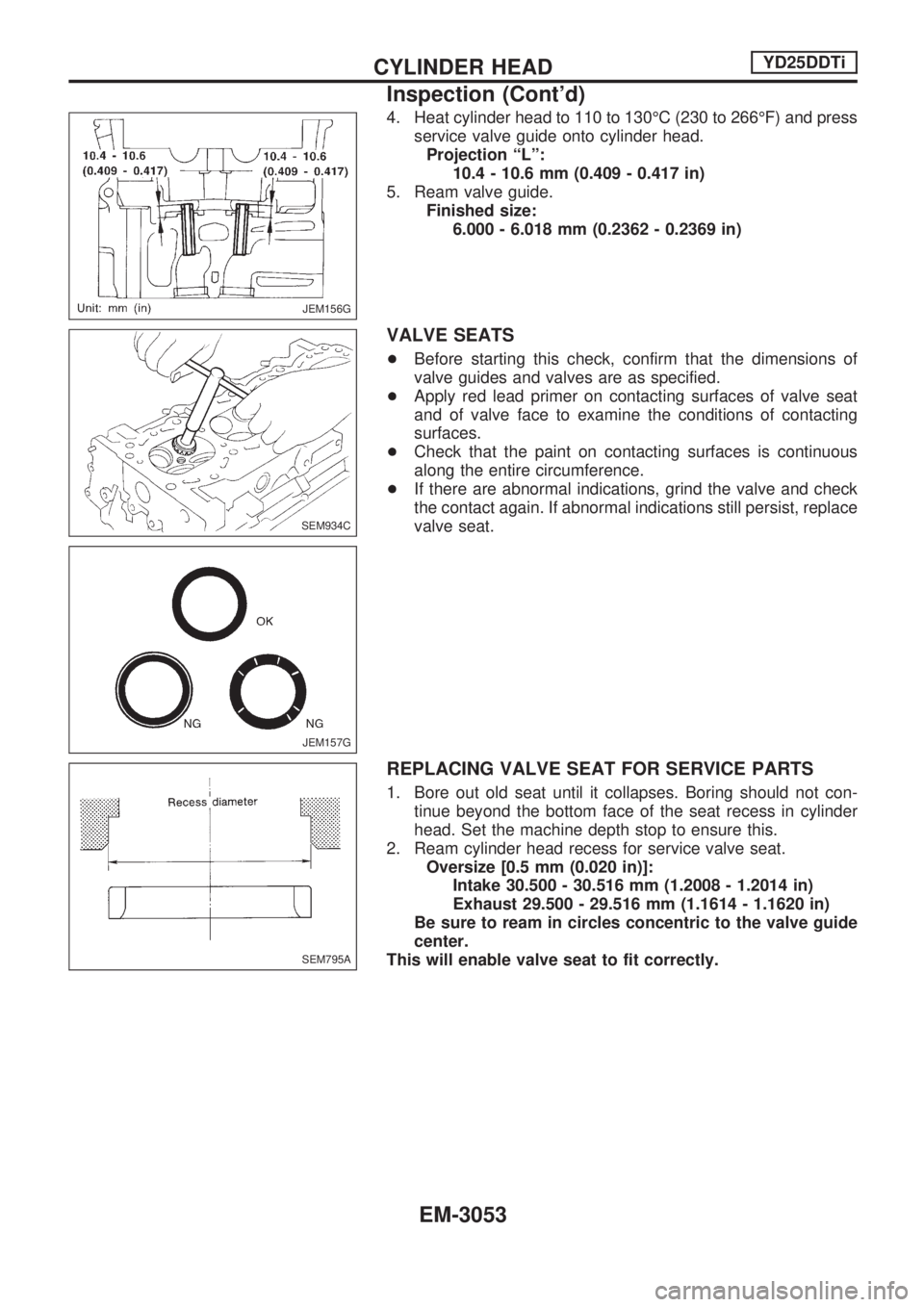
4. Heat cylinder head to 110 to 130ÉC (230 to 266ÉF) and press
service valve guide onto cylinder head.
Projection ªLº:
10.4 - 10.6 mm (0.409 - 0.417 in)
5. Ream valve guide.
Finished size:
6.000 - 6.018 mm (0.2362 - 0.2369 in)
VALVE SEATS
+Before starting this check, confirm that the dimensions of
valve guides and valves are as specified.
+Apply red lead primer on contacting surfaces of valve seat
and of valve face to examine the conditions of contacting
surfaces.
+Check that the paint on contacting surfaces is continuous
along the entire circumference.
+If there are abnormal indications, grind the valve and check
the contact again. If abnormal indications still persist, replace
valve seat.
REPLACING VALVE SEAT FOR SERVICE PARTS
1. Bore out old seat until it collapses. Boring should not con-
tinue beyond the bottom face of the seat recess in cylinder
head. Set the machine depth stop to ensure this.
2. Ream cylinder head recess for service valve seat.
Oversize [0.5 mm (0.020 in)]:
Intake 30.500 - 30.516 mm (1.2008 - 1.2014 in)
Exhaust 29.500 - 29.516 mm (1.1614 - 1.1620 in)
Be sure to ream in circles concentric to the valve guide
center.
This will enable valve seat to fit correctly.
JEM156G
SEM934C
JEM157G
SEM795A
CYLINDER HEADYD25DDTi
Inspection (Cont'd)
EM-3053
Page 942 of 1306
Removal operation
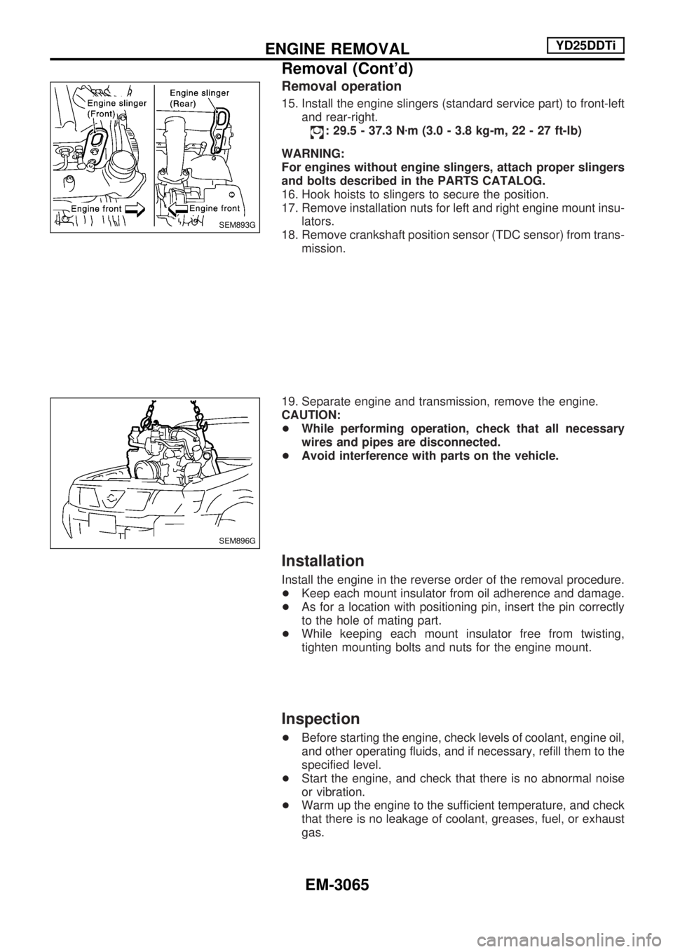
15. Install the engine slingers (standard service part) to front-left
and rear-right.
: 29.5 - 37.3 Nzm (3.0 - 3.8 kg-m, 22 - 27 ft-lb)
WARNING:
For engines without engine slingers, attach proper slingers
and bolts described in the PARTS CATALOG.
16. Hook hoists to slingers to secure the position.
17. Remove installation nuts for left and right engine mount insu-
lators.
18. Remove crankshaft position sensor (TDC sensor) from trans-
mission.
19. Separate engine and transmission, remove the engine.
CAUTION:
+While performing operation, check that all necessary
wires and pipes are disconnected.
+Avoid interference with parts on the vehicle.
Installation
Install the engine in the reverse order of the removal procedure.
+Keep each mount insulator from oil adherence and damage.
+As for a location with positioning pin, insert the pin correctly
to the hole of mating part.
+While keeping each mount insulator free from twisting,
tighten mounting bolts and nuts for the engine mount.
Inspection
+Before starting the engine, check levels of coolant, engine oil,
and other operating fluids, and if necessary, refill them to the
specified level.
+Start the engine, and check that there is no abnormal noise
or vibration.
+Warm up the engine to the sufficient temperature, and check
that there is no leakage of coolant, greases, fuel, or exhaust
gas.
SEM893G
SEM896G
ENGINE REMOVALYD25DDTi
Removal (Cont'd)
EM-3065
Page 944 of 1306
Removal and Installation
CAUTION:
+When installing bearings, pistons, or other sliding parts,
lubricate contacting surfaces with new engine oil.
+Place removed parts such as bearings and bearing caps
in their proper order and direction.
+When installing connecting rod nuts, and main bearing
cap bolts, apply new engine oil to threads and seating
surfaces.
+Do not allow any magnetic materials to contact the sig-
nal plate of flywheel.
+Do not remove the signal plate at back.
+Do not place the signal plate side facing under.
+Handle with care so as not to damage the signal plate
[especially four places on protrusions for signal of crank
position sensor (TDC sensor)].
Disassembly
PISTON AND CRANKSHAFT
1. Remove engine. Refer to ªENGINE REMOVALº, EM-3063.
2. Place engine on a work stand.
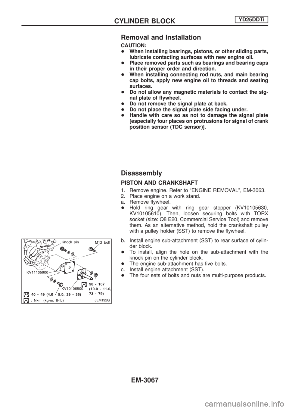
a. Remove flywheel.
+Hold ring gear with ring gear stopper (KV10105630,
KV10105610). Then, loosen securing bolts with TORX
socket (size: Q8 E20, Commercial Service Tool) and remove
them. As an alternative method, hold the crankshaft pulley
with a pulley holder (SST) to remove the flywheel.
b. Install engine sub-attachment (SST) to rear surface of cylin-
der block.
+To install, align the hole on the sub-attachment with the
knock pin on the cylinder block.
+The engine sub-attachment has five bolts.
c. Install engine attachment (SST).
+The four sets of bolts and nuts are multi-purpose products.
JEM192G
CYLINDER BLOCKYD25DDTi
EM-3067
Page 946 of 1306
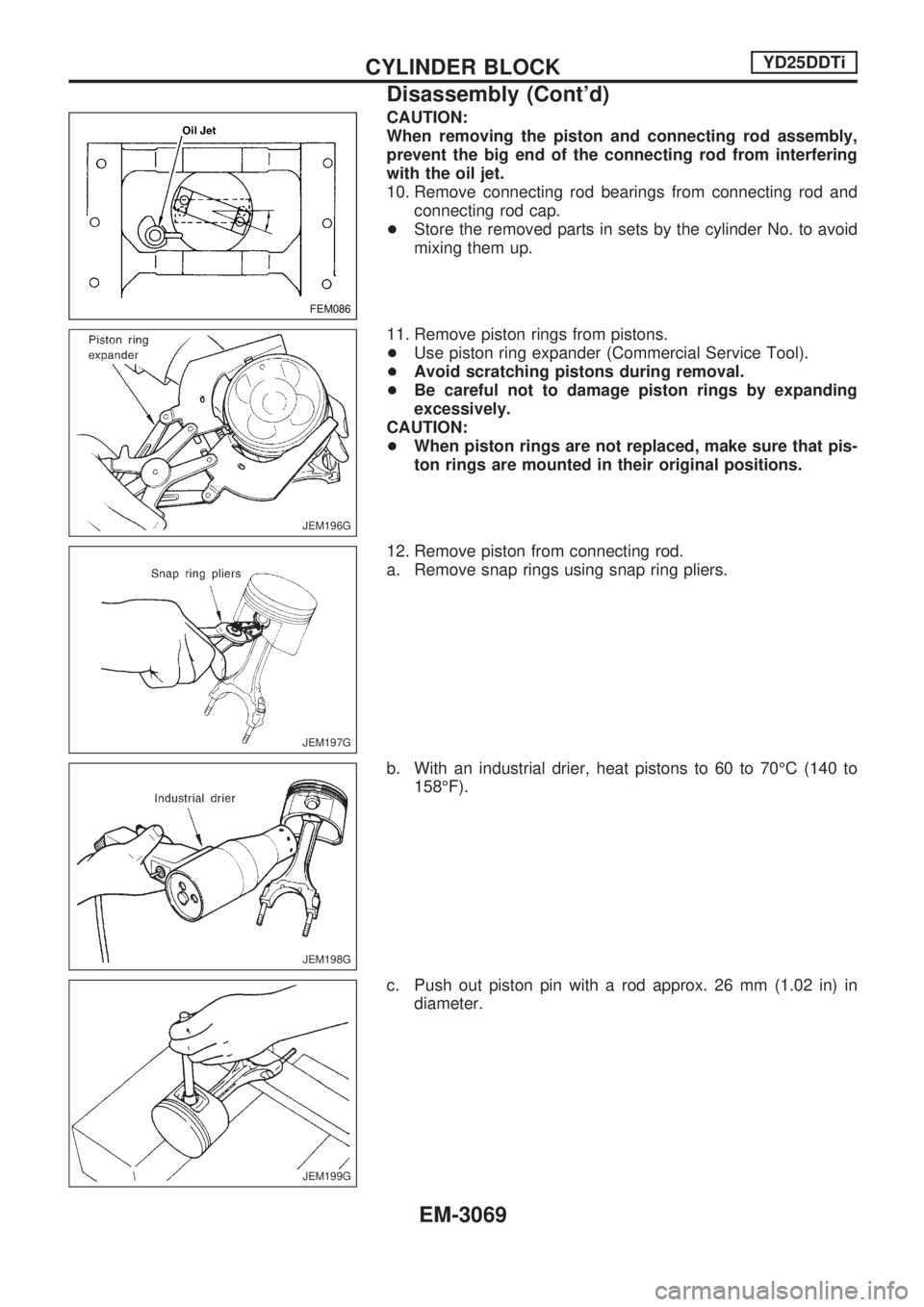
CAUTION:
When removing the piston and connecting rod assembly,
prevent the big end of the connecting rod from interfering
with the oil jet.
10. Remove connecting rod bearings from connecting rod and
connecting rod cap.
+Store the removed parts in sets by the cylinder No. to avoid
mixing them up.
11. Remove piston rings from pistons.
+Use piston ring expander (Commercial Service Tool).
+Avoid scratching pistons during removal.
+Be careful not to damage piston rings by expanding
excessively.
CAUTION:
+When piston rings are not replaced, make sure that pis-
ton rings are mounted in their original positions.
12. Remove piston from connecting rod.
a. Remove snap rings using snap ring pliers.
b. With an industrial drier, heat pistons to 60 to 70ÉC (140 to
158ÉF).
c. Push out piston pin with a rod approx. 26 mm (1.02 in) in
diameter.
FEM086
JEM196G
JEM197G
JEM198G
JEM199G
CYLINDER BLOCKYD25DDTi
Disassembly (Cont'd)
EM-3069
Page 947 of 1306
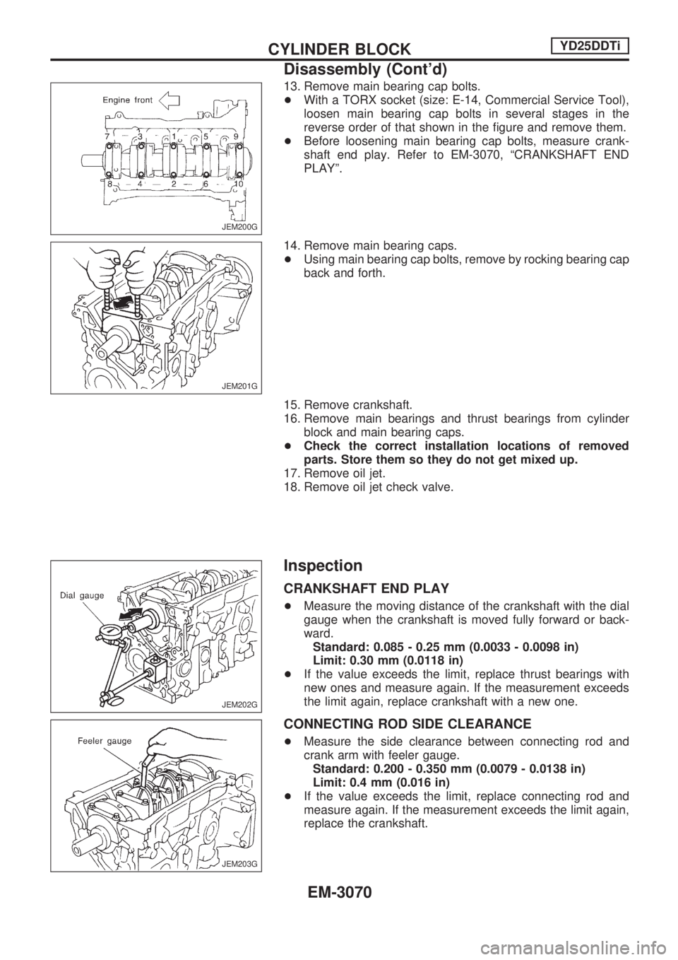
13. Remove main bearing cap bolts.
+With a TORX socket (size: E-14, Commercial Service Tool),
loosen main bearing cap bolts in several stages in the
reverse order of that shown in the figure and remove them.
+Before loosening main bearing cap bolts, measure crank-
shaft end play. Refer to EM-3070, ªCRANKSHAFT END
PLAYº.
14. Remove main bearing caps.
+Using main bearing cap bolts, remove by rocking bearing cap
back and forth.
15. Remove crankshaft.
16. Remove main bearings and thrust bearings from cylinder
block and main bearing caps.
+Check the correct installation locations of removed
parts. Store them so they do not get mixed up.
17. Remove oil jet.
18. Remove oil jet check valve.
Inspection
CRANKSHAFT END PLAY
+Measure the moving distance of the crankshaft with the dial
gauge when the crankshaft is moved fully forward or back-
ward.
Standard: 0.085 - 0.25 mm (0.0033 - 0.0098 in)
Limit: 0.30 mm (0.0118 in)
+If the value exceeds the limit, replace thrust bearings with
new ones and measure again. If the measurement exceeds
the limit again, replace crankshaft with a new one.
CONNECTING ROD SIDE CLEARANCE
+Measure the side clearance between connecting rod and
crank arm with feeler gauge.
Standard: 0.200 - 0.350 mm (0.0079 - 0.0138 in)
Limit: 0.4 mm (0.016 in)
+If the value exceeds the limit, replace connecting rod and
measure again. If the measurement exceeds the limit again,
replace the crankshaft.
JEM200G
JEM201G
JEM202G
JEM203G
CYLINDER BLOCKYD25DDTi
Disassembly (Cont'd)
EM-3070
Page 951 of 1306
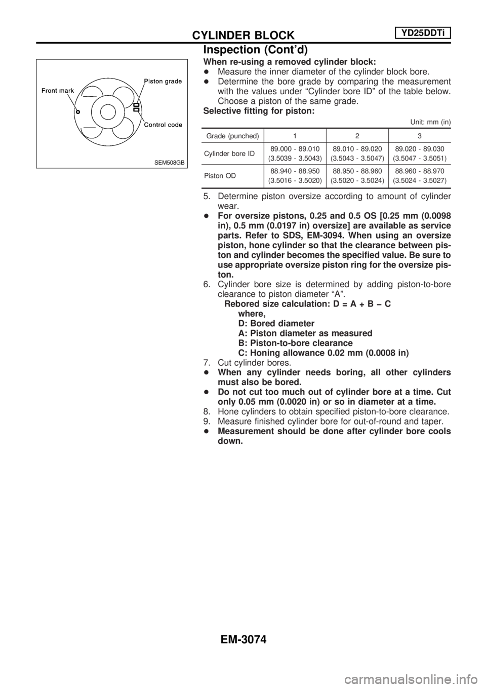
When re-using a removed cylinder block:
+Measure the inner diameter of the cylinder block bore.
+Determine the bore grade by comparing the measurement
with the values under ªCylinder bore IDº of the table below.
Choose a piston of the same grade.
Selective fitting for piston:
Unit: mm (in)
Grade (punched) 1 2 3
Cylinder bore ID89.000 - 89.010
(3.5039 - 3.5043)89.010 - 89.020
(3.5043 - 3.5047)89.020 - 89.030
(3.5047 - 3.5051)
Piston OD88.940 - 88.950
(3.5016 - 3.5020)88.950 - 88.960
(3.5020 - 3.5024)88.960 - 88.970
(3.5024 - 3.5027)
5. Determine piston oversize according to amount of cylinder
wear.
+For oversize pistons, 0.25 and 0.5 OS [0.25 mm (0.0098
in), 0.5 mm (0.0197 in) oversize] are available as service
parts. Refer to SDS, EM-3094. When using an oversize
piston, hone cylinder so that the clearance between pis-
ton and cylinder becomes the specified value. Be sure to
use appropriate oversize piston ring for the oversize pis-
ton.
6. Cylinder bore size is determined by adding piston-to-bore
clearance to piston diameter ªAº.
Rebored size calculation:D=A+BþC
where,
D: Bored diameter
A: Piston diameter as measured
B: Piston-to-bore clearance
C: Honing allowance 0.02 mm (0.0008 in)
7. Cut cylinder bores.
+When any cylinder needs boring, all other cylinders
must also be bored.
+Do not cut too much out of cylinder bore at a time. Cut
only 0.05 mm (0.0020 in) or so in diameter at a time.
8. Hone cylinders to obtain specified piston-to-bore clearance.
9. Measure finished cylinder bore for out-of-round and taper.
+Measurement should be done after cylinder bore cools
down.
SEM508GB
CYLINDER BLOCKYD25DDTi
Inspection (Cont'd)
EM-3074
Page 958 of 1306
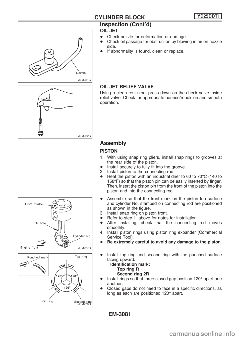
OIL JET
+Check nozzle for deformation or damage.
+Check oil passage for obstruction by blowing in air on nozzle
side.
+If abnormality is found, clean or replace.
OIL JET RELIEF VALVE
Using a clean resin rod, press down on the check valve inside
relief valve. Check for appropriate bounce/repulsion and smooth
operation.
Assembly
PISTON
1. With using snap ring pliers, install snap rings to grooves at
the rear side of the piston.
+Install securely to fully fit into the groove.
2. Install piston to the connecting rod.
+Heat the piston with an industrial drier to 60 to 70ÉC (140 to
158ÉF) so that the piston pin can be easily inserted by finger.
Then, insert the piston pin from the front of the piston into the
piston and into the connecting rod.
+Assemble so that the front mark on the piston top surface
and cylinder No. stamped on connecting rod are positioned
as shown in the figure.
3. Install snap ring on piston front.
+Refer to step 1. above for notes for installation.
+After installing, check that the connecting rod moves
smoothly.
4. Install piston rings using piston ring expander (Commercial
Service Tool).
+Be extremely careful to avoid any damage to the piston.
+Install top ring and second ring with the punched surface
facing upward.
Identification mark:
Top ring R
Second ring 2R
+Install rings so that three closed gap position 120É apart one
another.
+Closed gaps do not need to face in a specific directions, as
long as each are positioned 120É apart.
JEM221G
JEM222G
JEM227G
JEM228G
CYLINDER BLOCKYD25DDTi
Inspection (Cont'd)
EM-3081
Page 960 of 1306
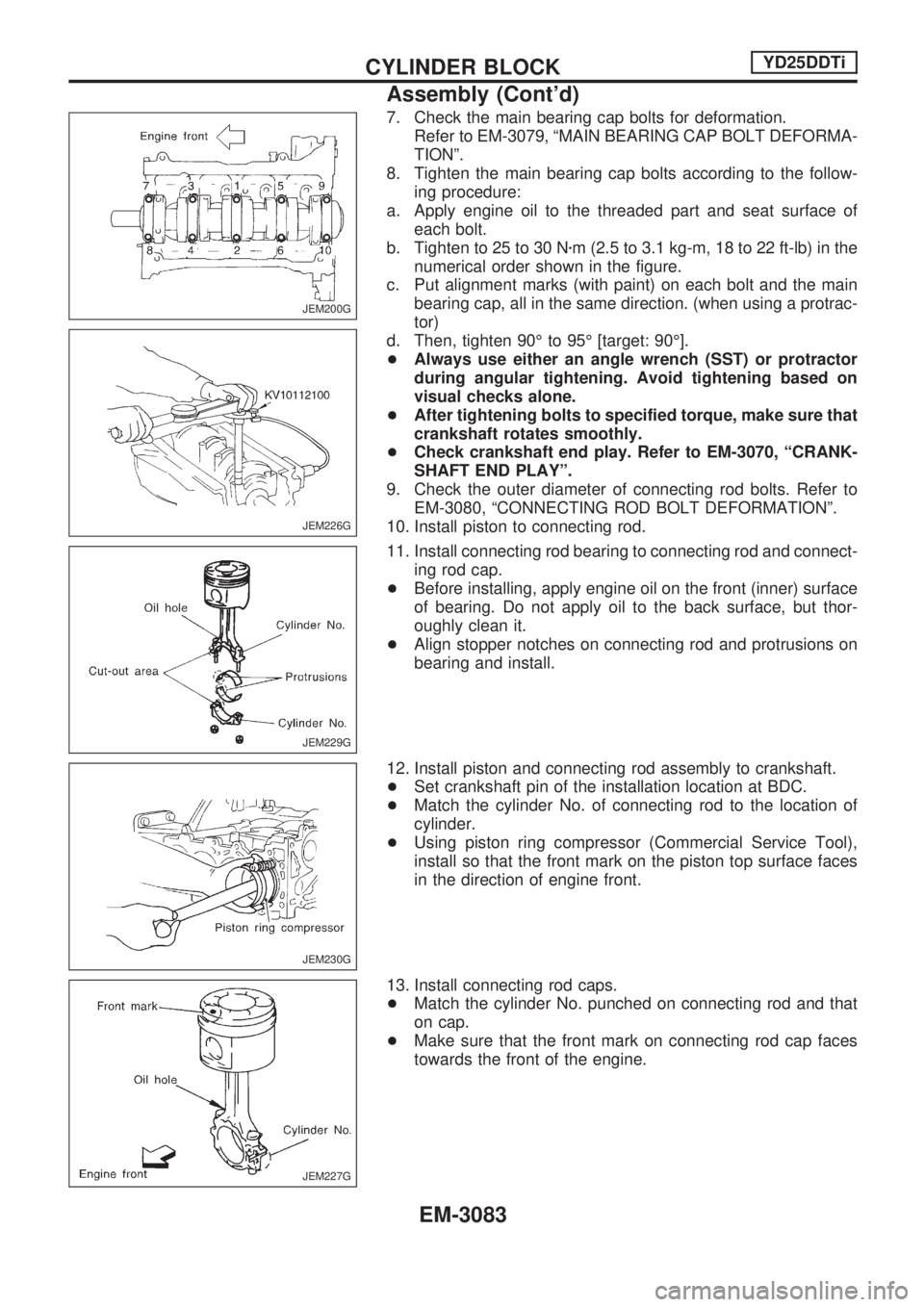
7. Check the main bearing cap bolts for deformation.
Refer to EM-3079, ªMAIN BEARING CAP BOLT DEFORMA-
TIONº.
8. Tighten the main bearing cap bolts according to the follow-
ing procedure:
a. Apply engine oil to the threaded part and seat surface of
each bolt.
b. Tighten to 25 to 30 Nzm (2.5 to 3.1 kg-m, 18 to 22 ft-lb) in the
numerical order shown in the figure.
c. Put alignment marks (with paint) on each bolt and the main
bearing cap, all in the same direction. (when using a protrac-
tor)
d. Then, tighten 90É to 95É [target: 90É].
+Always use either an angle wrench (SST) or protractor
during angular tightening. Avoid tightening based on
visual checks alone.
+After tightening bolts to specified torque, make sure that
crankshaft rotates smoothly.
+Check crankshaft end play. Refer to EM-3070, ªCRANK-
SHAFT END PLAYº.
9. Check the outer diameter of connecting rod bolts. Refer to
EM-3080, ªCONNECTING ROD BOLT DEFORMATIONº.
10. Install piston to connecting rod.
11. Install connecting rod bearing to connecting rod and connect-
ing rod cap.
+Before installing, apply engine oil on the front (inner) surface
of bearing. Do not apply oil to the back surface, but thor-
oughly clean it.
+Align stopper notches on connecting rod and protrusions on
bearing and install.
12. Install piston and connecting rod assembly to crankshaft.
+Set crankshaft pin of the installation location at BDC.
+Match the cylinder No. of connecting rod to the location of
cylinder.
+Using piston ring compressor (Commercial Service Tool),
install so that the front mark on the piston top surface faces
in the direction of engine front.
13. Install connecting rod caps.
+Match the cylinder No. punched on connecting rod and that
on cap.
+Make sure that the front mark on connecting rod cap faces
towards the front of the engine.
JEM200G
JEM226G
JEM229G
JEM230G
JEM227G
CYLINDER BLOCKYD25DDTi
Assembly (Cont'd)
EM-3083