Page 990 of 1306

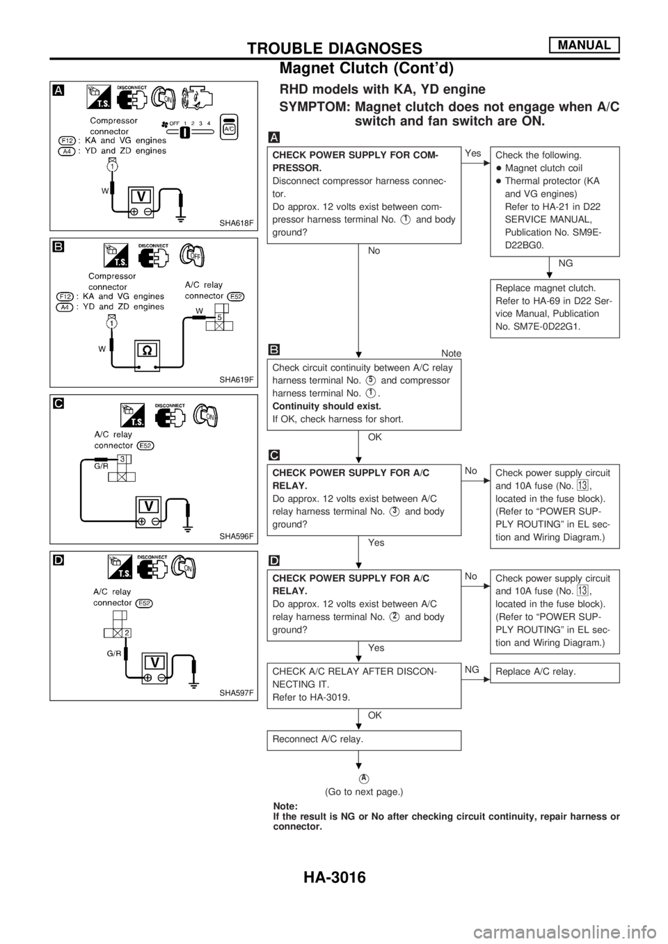
RHD models with KA, YD engine
SYMPTOM: Magnet clutch does not engage when A/C
switch and fan switch are ON.
CHECK POWER SUPPLY FOR COM-
PRESSOR.
Disconnect compressor harness connec-
tor.
Do approx. 12 volts exist between com-
pressor harness terminal No.
V1and body
ground?
No
cYes
Check the following.
+Magnet clutch coil
+Thermal protector (KA
and VG engines)
Refer to HA-21 in D22
SERVICE MANUAL,
Publication No. SM9E-
D22BG0.
NG
Replace magnet clutch.
Refer to HA-69 in D22 Ser-
vice Manual, Publication
No. SM7E-0D22G1.
Note
Check circuit continuity between A/C relay
harness terminal No.
V5and compressor
harness terminal No.
V1.
Continuity should exist.
If OK, check harness for short.
OK
CHECK POWER SUPPLY FOR A/C
RELAY.
Do approx. 12 volts exist between A/C
relay harness terminal No.
V3and body
ground?
Yes
cNo
Check power supply circuit
and 10A fuse (No.
13,
located in the fuse block).
(Refer to ªPOWER SUP-
PLY ROUTINGº in EL sec-
tion and Wiring Diagram.)
CHECK POWER SUPPLY FOR A/C
RELAY.
Do approx. 12 volts exist between A/C
relay harness terminal No.
V2and body
ground?
Yes
cNo
Check power supply circuit
and 10A fuse (No.
13,
located in the fuse block).
(Refer to ªPOWER SUP-
PLY ROUTINGº in EL sec-
tion and Wiring Diagram.)
CHECK A/C RELAY AFTER DISCON-
NECTING IT.
Refer to HA-3019.
OK
cNG
Replace A/C relay.
Reconnect A/C relay.
VA
(Go to next page.)
Note:
If the result is NG or No after checking circuit continuity, repair harness or
connector.
SHA618F
SHA619F
SHA596F
SHA597F
.
.
.
.
.
.
.
TROUBLE DIAGNOSESMANUAL
Magnet Clutch (Cont'd)
HA-3016
Page 992 of 1306
VB
CHECK A/C SWITCH.
Refer to HA-21 in D22 SERVICE
MANUAL, Publication No. SM9E-
D22BG0.
OK
cNG
Replace A/C switch.
Note
Check circuit continuity between A/C
switch harness terminal No.
V12and fan
switch harness terminal No.
V25.
Continuity should exist.
If OK, check harness for short.
OK
CHECK FAN SWITCH
Refer to HA-21 in D22 SERVICE
MANUAL, Publication No. SM9E-
D22BG0.
OK
cNG
Replace fan switch.
Note
Check circuit continuity between fan
switch harness terminal No.
V26and body
ground.
Continuity should exist.
If OK, check harness for short.
Note:
If the result is NG or No after checking circuit continuity,
repair harness or connector.
RHA465H
RHA466HA
RHA322GA
.
.
.
.
TROUBLE DIAGNOSESMANUAL
Magnet Clutch (Cont'd)
HA-3018
Page 993 of 1306
VC
Note
Check circuit continuity between thermo
control amp. harness terminal No.
V3
and triple-pressure switch harness termi-
nal No.
V1.
Continuity should exist.
If OK, check harness for short.
OK
CHECK TRIPLE-PRESSURE SWITCH.
Refer to HA-22 in D22 SERVICE
MANUAL, Publication No. SM9E-
D22BG0.
OK
cNG
Replace triple-pressure
switch.
Note
Check circuit continuity between triple-
pressure switch harness terminal No.
V4
and ECM harness terminal No.V21orV46.
Continuity should exist.
If OK, check harness for short.
OK
Replace ECM.
Note:
If the result is NG or No after checking circuit continuity,
repair harness or connector.
ELECTRICAL COMPONENT INSPECTION
A/C Relay
Check continuity between terminal Nos. 3 and 5.
Conditions Continuity
12V direct current supply between
terminal Nos. 1 and 2Yes
No current supply No
If NG, replace relay.
RHA328GC
RHA340GC
RHA638H
.
. .
.
.
TROUBLE DIAGNOSESMANUAL
Magnet Clutch (Cont'd)
HA-3019
Page 1000 of 1306
Magnet Clutch
TROUBLE DIAGNOSIS PROCEDURE FOR MAGNET CLUTCH
SYMPTOM:
+Magnet clutch does not engage.
Inspection flow
*1: HA-2035
*2: HA-2036
*3: HA-2038
*4: HA-2040
*5: HA-2080*6: HA-2082
*7: HA-2084
*8: HA-2087
*9: HA-2052
*10: HA-2041*11: HA-3027
*12: HA-27 in D22 Service
Manual, Publication No.
SM8E-0D22E0E
Note: *1 - *10: Refer to D22 SERVICE MANUAL, Publication No. SM9E-D22BE0E.
SHA341FA
TROUBLE DIAGNOSESAUTO
HA-3026
Page 1002 of 1306

VA
NoteNote
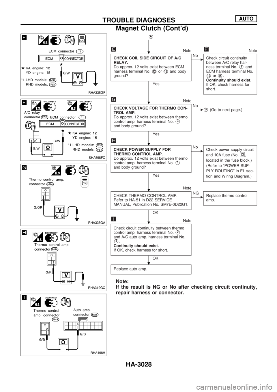
CHECK COIL SIDE CIRCUIT OF A/C
RELAY.
Do approx. 12 volts exist between ECM
harness terminal No.
V12orV15and body
ground?
Yes
cNo
Check circuit continuity
between A/C relay har-
ness terminal No.
V1and
ECM harness terminal No.
V12orV15.
Continuity should exist.
If OK, check harness for
short.
Note
CHECK VOLTAGE FOR THERMO CON-
TROL AMP.
Do approx. 12 volts exist between thermo
control amp. harness terminal No.
V3
and body ground?
Yes
cNoVB(Go to next page.)
CHECK POWER SUPPLY FOR
THERMO CONTROL AMP.
Do approx. 12 volts exist between thermo
control amp. harness terminal No.
V1
and body ground?
Yes
cNo
Check power supply circuit
and 10A fuse (No.
13,
located in the fuse block.)
(Refer to ªPOWER SUP-
PLY ROUTINGº in EL sec-
tion and Wiring Diagram.)
Note
CHECK THERMO CONTROL AMP.
Refer to HA-51 in D22 SERVICE
MANUAL, Publication No. SM7E-0D22G1.
OK
cNG
Replace thermo control
amp.
Note
Check circuit continuity between thermo
control amp. harness terminal No.
V2
and A/C auto amp. harness terminal No.
V4.
Continuity should exist.
If OK, check harness for short.
OK
Replace auto amp.
Note:
If the result is NG or No after checking circuit continuity,
repair harness or connector.
RHA335GF
SHA598FC
RHA338GA
RHA319GC
RHA498H
.
.
.
.
.
.
TROUBLE DIAGNOSESAUTO
Magnet Clutch (Cont'd)
HA-3028
Page 1003 of 1306
VB
Note
Check circuit continuity between thermo
control amp. harness terminal No.
V3
and triple-pressure switch harness termi-
nal No.
V1.
Continuity should exist.
If OK, check harness for short.
OK
CHECK TRIPLE-PRESSURE SWITCH.
Refer to HA-22 in D22 SERVICE
MANUAL, Publication No. SM9E-
D22BG0.
OK
cNG
Replace triple-pressure
switch.
Note
Check circuit continuity between triple-
pressure switch harness terminal No.
V4
and ECM harness terminal No.V21.
Continuity should exist.
If OK, check harness for short.
OK
Replace ECM.
Note:
If the result is NG or No after checking circuit continuity,
repair harness or connector.
ELECTRICAL COMPONENT INSPECTION
A/C Relay
Check continuity between terminal Nos. 3 and 5.
Conditions Continuity
12V direct current supply between
terminal Nos. 1 and 2Yes
No current supply No
If NG, replace relay.
RHA328GC
RHA178I
RHA638H
.
. .
.
.
TROUBLE DIAGNOSESAUTO
Magnet Clutch (Cont'd)
HA-3029
Page 1004 of 1306
Refrigerant Lines
+Refer to page HA-3002 regarding ªPrecautions for Refriger-
ant Connectionº.
YD ENGINE
RHA179I
SERVICE PROCEDURES
HA-3030
Page 1005 of 1306

Checking Refrigerant Leaks
CHECKING PROCEDURE
To prevent inaccurate or false readings, make sure there is
no refrigerant vapor or tobacco smoke in the vicinity of the
vehicle. Perform the leak test in calm area (low air/wind
movement) so that the leaking refrigerant is not dispersed.
1. Turn engine off.
2. Connect a suitable A/C manifold gauge set to the A/C ser-
vice ports.
3. Check if the A/C refrigerant pressure is at least 345 kPa
(3.452 bar, 3.52 kg/cm
2, 50 psi) above 16ÉC (61ÉF). If less
than specification, evacuate and recharge the system with
the specified amount of refrigerant.
NOTE: At temperatures below 16ÉC (61ÉF), leaks may not be
detected since the system may not reach 345 kPa
(3.452 bar, 3.52 kg/cm
2, 50 psi).
4. Conduct the leak test from the high side to the low side at
points
jathroughjn. Refer to HA-3030.
Perform a leak check for the following areas carefully. Clean
the component to be checked and move the leak detector
probe completely around the connection/component.
+Compressor
Check the fitting of high and low pressure hoses, relief valve
and shaft seal.
+Liquid tank
Check the pressure switch, tube fitting, weld seams and the
fusible plug mounts.
+Service valves
Check all around the service valves. Ensure service valve
caps are secured on the service valves (to prevent leaks).
NOTE: After removing A/C manifold gauge set from service
valves, wipe any residue from valves to prevent any
false readings by leak detector.
+Cooling unit (Evaporator)
Turn blower fan on ªHighº for at least 15 seconds to dissipate
any refrigerant trace in the cooling unit. Insert the leak detec-
tor probe into the drain hose immediately after stopping the
engine. (Keep the probe inserted for at least ten seconds.)
5. If a leak detector detects a leak, verify at least once by
blowing compressed air into area of suspected leak, then
repeat check.
6. Do not stop when one leak is found. Continue to check for
additional leaks at all system components.
7. Start engine.
8. Set the heater A/C control as follows:
a. A/C switch ON
b. Face mode
c. Recirculation switch ON
d. Max cold temperature
e. Fan speed high
9. Run engine at 1,500 rpm for at least 2 minutes.
10. Turn engine off and perform leak check again following steps
4 through 6 above.
SERVICE PROCEDURESMANUAL AND AUTO
HA-3031