Page 879 of 1306
YD25DDTi
SERVICE DATA AND SPECIFICATIONS
(SDS).................................................................... 3088
General Specifications ..................................... 3088
Compression Pressure .................................... 3088
Cylinder Head .................................................. 3088
Valve ................................................................ 3089
Valve Seat........................................................ 3092Camshaft and Camshaft Bearing .................... 3093
Cylinder Block .................................................. 3094
Piston, Piston Ring and Piston Pin.................. 3094
Connecting Rod ............................................... 3095
Crankshaft ........................................................ 3096
Available Main Bearing .................................... 3096
Available Connecting Rod Bearing .................. 3097
Miscellaneous Components ............................. 3097
EM-3002
Page 881 of 1306
Special Service Tools (YD25DDTi engine)
Tool number
Tool nameDescription
ST0501S000
Engine stand assembly
1 ST05011000
Engine stand
2 ST05012000
Base
NT042
Disassembling and assembling
KV10106500
Engine stand shaft
NT028
KV11105900
Engine sub-attachment
NT799
KV10115900 has been replaced with
KV10106500.
KV10115600
Valve oil seal drift
NT603
Installing valve oil seal
Use side A.
Side A
a: 20 (0.79) dia.
b: 13 (0.51) dia.
c: 10.3 (0.406) dia.
d: 8 (0.31) dia.
e: 10.7 (0.421)
f: 5 (0.20)
Unit: mm (in)
KV10107902
Valve oil seal puller
1 KV10116100
Valve oil seal puller adapter
NT605
Removing valve oil seal
KV11103000
Injection pump drive gear
puller
NT676
Removing crankshaft pulley
PREPARATION
EM-3004
Page 882 of 1306
Tool number
Tool nameDescription
KV101056S0
Ring gear stopper
1 KV10105630
Adapter
2 KV10105610
Plate
NT617
Preventing crankshaft from rotating
a: 3 (0.12)
b: 6.4 (0.252)
c: 2.8 (0.110)
d: 6.6 (0.260)
e: 107 (4.21)
f: 14 (0.55)
g: 20 (0.79)
h: 14 (0.55) dia.
Unit: mm (in)
KV101151S0
Lifter stopper set
1 KV10115110
Camshaft pliers
2 KV10115120
Lifter stopper
NT041
Changing valve lifter shims
ST16610001
Pilot bushing puller
NT045
Removing crankshaft pilot bushing
KV10111100
Seal cutter
NT046
Removing steel oil pan and rear timing chain
case
WS39930000
Tube presser
NT052
Pressing the tube of liquid gasket
KV10112100
Angle wrench
NT014
Tightening bolts for bearing cap, cylinder head,
etc.
KV10109300
Pulley holder
NT628
a: 68 mm (2.68 in)
b: 8 mm (0.31 in) dia.
PREPARATION
Special Service Tools (YD25DDTi engine)
(Cont'd)
EM-3005
Page 883 of 1306
Tool number
Tool nameDescription
KV11106010
Hexagon wrench
NT801
a: 5 mm (0.20 in) (Face to face)
b: 20 mm (0.79 in)
KV11106020
Hexagon wrench
NT803
a: 6 mm (0.24 in) (Face to face)
b: 20 mm (0.79 in)
KV11106030
Positioning stopper pin
NT804
a: 6 mm (0.24 in) dia.
b: 80 mm (3.15 in)
KV11106040
TORX wrench
NT805
a: T70
b: 26 mm (1.02 in)
KV11106050
Hexagonal wrench
SBIA0224E
a: 6 mm (0.24 in) (Face to face)
b: 42 mm (1.65 in)
Removing and installing mounting bolts of fuel
injection pump sprocket
PREPARATION
Special Service Tools (YD25DDTi engine)
(Cont'd)
EM-3006
Page 884 of 1306
Commercial Service Tools (YD25DDTi
engine)
Tool name Description
Valve seat cutter set
NT048
Finishing valve seat dimensions
Piston ring compressor
NT044
Installing piston assembly into cylinder bore
Piston ring expander
NT030
Removing and installing piston ring
TORX socket
NT807
Standard Universal
NT808
PREPARATION
EM-3007
Page 894 of 1306

5. Remove lower oil pan.
a. Insert Tool between upper oil pan and lower oil pan.
+Be careful not to damage aluminum mating surface.
+ Do not insert screwdriver, or oil pan flange will be
deformed.
b. Slide Tool by tapping on the side of the Tool with a hammer.
c. Remove lower oil pan.
6. Remove oil strainer.
7. Remove air conditioner compressor and bracket.
8. Remove left side of the tie rod end Ð 2WD models only.
9. Remove front final drive together with differential mounting member and front suspension member. Refer to PD, MT and
FAsectionsinNISSANServiceManual(First Edition of
SM3E00-1D22E0E) Ð 4WD models only.
10.Removecrankshaftpositionsensor.RefertoEM sectionin NISSANServiceManual(Supplement III of SM3E00-
1D22E0E).
11. Remove transmission. Refer to MT section in NISSAN Ser- viceManual(Supplement III of SM3E00-1D22E0E)Ð2WD
models only.
12. Remove transmission with transfer assembly. Refer to MT sectioninNISSANServiceManual(Supplement III of
SM3E00-1D22E0E) Ð 4WD models only.
13. Remove clutch cover and clutch disc. Refer to CL section in NISSANServiceManual(Supplement I of SM3E00-
1D22E0E).
14. Remove flywheel and engine rear plate. Refer to EM section (``Disassembly'', ``CYLINDER BLOCK'') in NISSAN Service
Manual(Supplement III of SM3E00-1D22E0E).
SEM852G
SEM865G
SEM600F
OILPAN YD25DDTi
Removal (Cont'd)
EM-3017
Page 896 of 1306

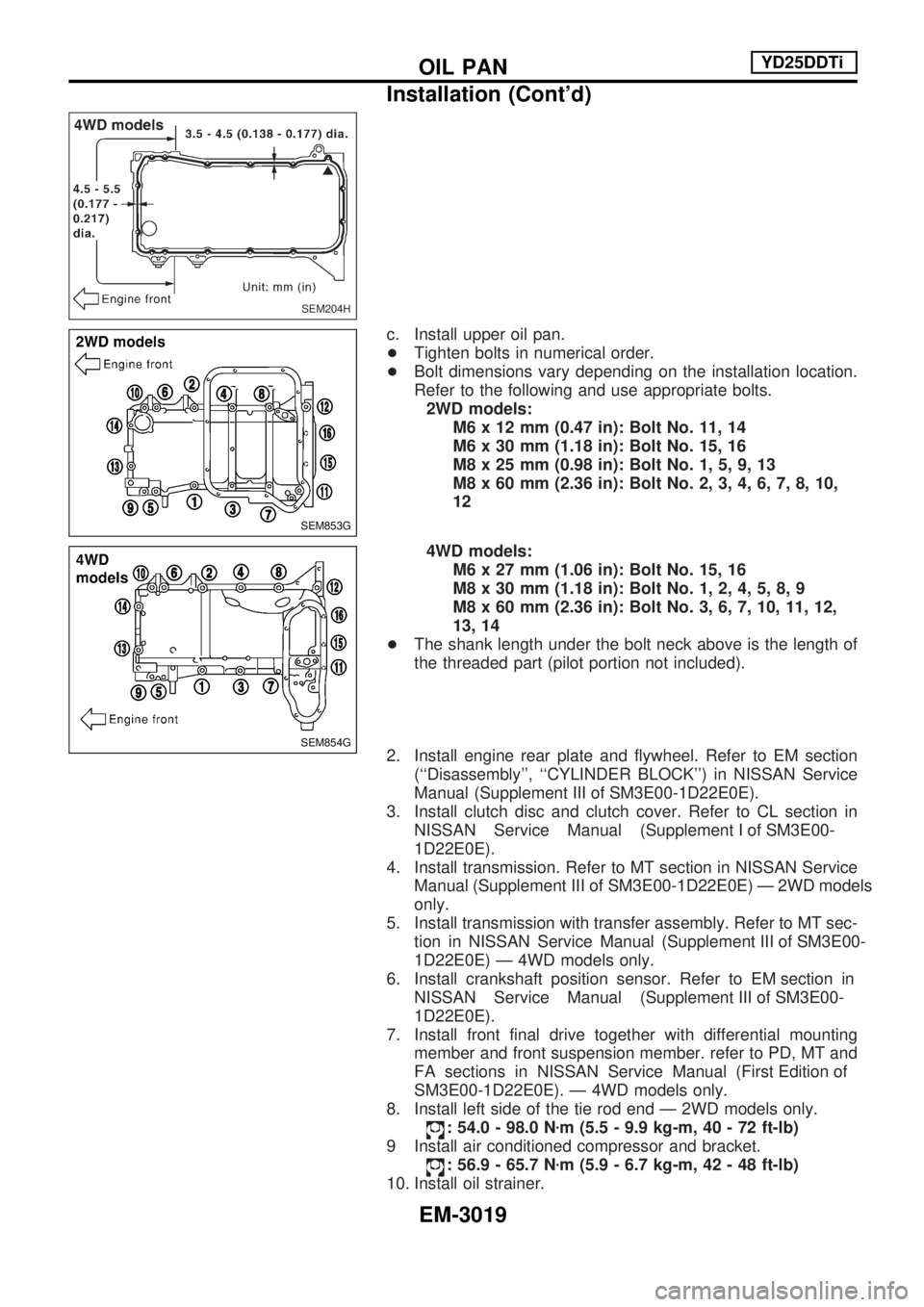
c. Install upper oil pan.
+Tighten bolts in numerical order.
+ Bolt dimensions vary depending on the installation location.
Refer to the following and use appropriate bolts.
2WD models: M6 x 12 mm (0.47 in): Bolt No. 11, 14
M6 x 30 mm (1.18 in): Bolt No. 15, 16
M8 x 25 mm (0.98 in): Bolt No. 1, 5, 9, 13
M8 x 60 mm (2.36 in): Bolt No. 2, 3, 4, 6, 7, 8, 10,
12
4WD models: M6 x 27 mm (1.06 in): Bolt No. 15, 16
M8 x 30 mm (1.18 in): Bolt No. 1, 2, 4, 5, 8, 9
M8 x 60 mm (2.36 in): Bolt No. 3, 6, 7, 10, 11, 12,
13, 14
+ The shank length under the bolt neck above is the length of
the threaded part (pilot portion not included).
2. Install engine rear plate and flywheel. Refer to EM section (``Disassembly'', ``CYLINDER BLOCK'') in NISSAN Service
Manual(Supplement III of SM3E00-1D22E0E).
3. Install clutch disc and clutch cover. Refer to CL section in NISSANServiceManual(Supplement I of SM3E00-
1D22E0E).
4. Install transmission. Refer to MT section in NISSAN Service Manual(Supplement III of SM3E00-1D22E0E)Ð2WDmodels
only.
5. Install transmission with transfer assembly. Refer to MT sec- tioninNISSANServiceManual(Supplement III of SM3E00-
1D22E0E) Ð 4WD models only.
6.Installcrankshaftpositionsensor.RefertoEM sectionin NISSANServiceManual(Supplement III of SM3E00-
1D22E0E).
7. Install front final drive together with differential mounting member and front suspension member. refer to PD, MT and
FAsectionsinNISSANServiceManual(First Edition of
SM3E00-1D22E0E). Ð 4WD models only.
8. Install left side of the tie rod end Ð 2WD models only.
: 54.0 - 98.0 N zm (5.5 - 9.9 kg-m, 40 - 72 ft-lb)
9 Install air conditioned compressor and bracket.
: 56.9 - 65.7 N zm (5.9 - 6.7 kg-m, 42 - 48 ft-lb)
10. Install oil strainer.
SEM204H
SEM853G
SEM854G
OILPAN YD25DDTi
Installation (Cont'd)
EM-3019
Page 929 of 1306

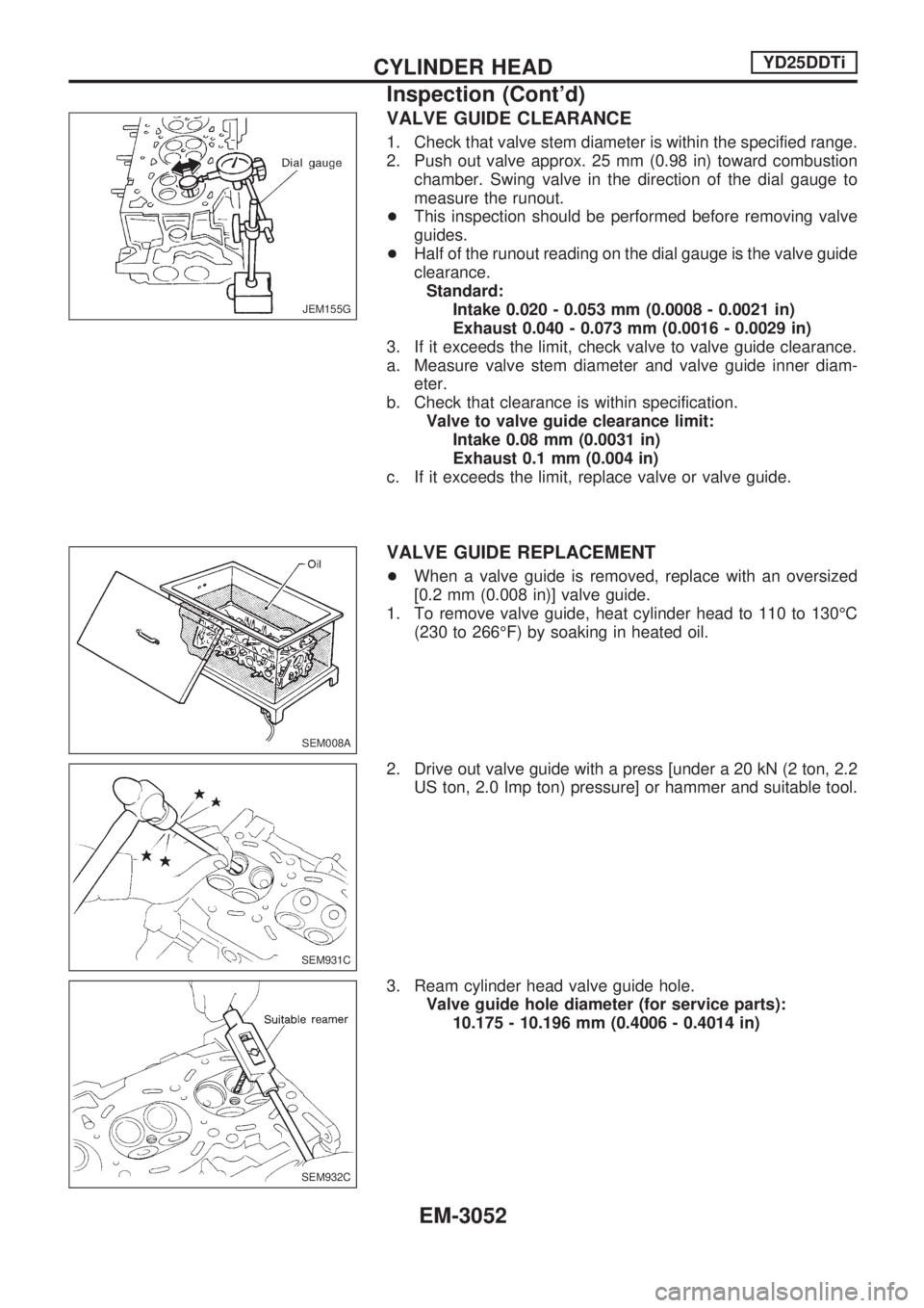
VALVE GUIDE CLEARANCE
1. Check that valve stem diameter is within the specified range.
2. Push out valve approx. 25 mm (0.98 in) toward combustion
chamber. Swing valve in the direction of the dial gauge to
measure the runout.
+This inspection should be performed before removing valve
guides.
+Half of the runout reading on the dial gauge is the valve guide
clearance.
Standard:
Intake 0.020 - 0.053 mm (0.0008 - 0.0021 in)
Exhaust 0.040 - 0.073 mm (0.0016 - 0.0029 in)
3. If it exceeds the limit, check valve to valve guide clearance.
a. Measure valve stem diameter and valve guide inner diam-
eter.
b. Check that clearance is within specification.
Valve to valve guide clearance limit:
Intake 0.08 mm (0.0031 in)
Exhaust 0.1 mm (0.004 in)
c. If it exceeds the limit, replace valve or valve guide.
VALVE GUIDE REPLACEMENT
+When a valve guide is removed, replace with an oversized
[0.2 mm (0.008 in)] valve guide.
1. To remove valve guide, heat cylinder head to 110 to 130ÉC
(230 to 266ÉF) by soaking in heated oil.
2. Drive out valve guide with a press [under a 20 kN (2 ton, 2.2
US ton, 2.0 Imp ton) pressure] or hammer and suitable tool.
3. Ream cylinder head valve guide hole.
Valve guide hole diameter (for service parts):
10.175 - 10.196 mm (0.4006 - 0.4014 in)
JEM155G
SEM008A
SEM931C
SEM932C
CYLINDER HEADYD25DDTi
Inspection (Cont'd)
EM-3052