2001 NISSAN PICK-UP service
[x] Cancel search: servicePage 750 of 1306
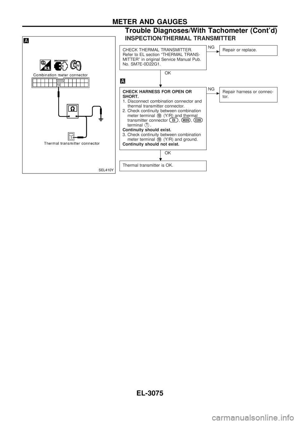
INSPECTION/THERMAL TRANSMITTER
CHECK THERMAL TRANSMITTER.
Refer to EL section ªTHERMAL TRANS-
MITTERº in original Service Manual Pub.
No. SM7E-0D22G1.
OK
cNG
Repair or replace.
CHECK HARNESS FOR OPEN OR
SHORT.
1. Disconnect combination connector and
thermal transmitter connector.
2. Check continuity between combination
meter terminal
V19(Y/R) and thermal
transmitter connectorE9,M209,E209terminalV1.
Continuity should exist.
3. Check continuity between combination
meter terminal
V19(Y/R) and ground.
Continuity should not exist.
OK
cNG
Repair harness or connec-
tor.
Thermal transmitter is OK.SEL410Y
.
.
METER AND GAUGES
Trouble Diagnoses/With Tachometer (Cont'd)
EL-3075
Page 754 of 1306
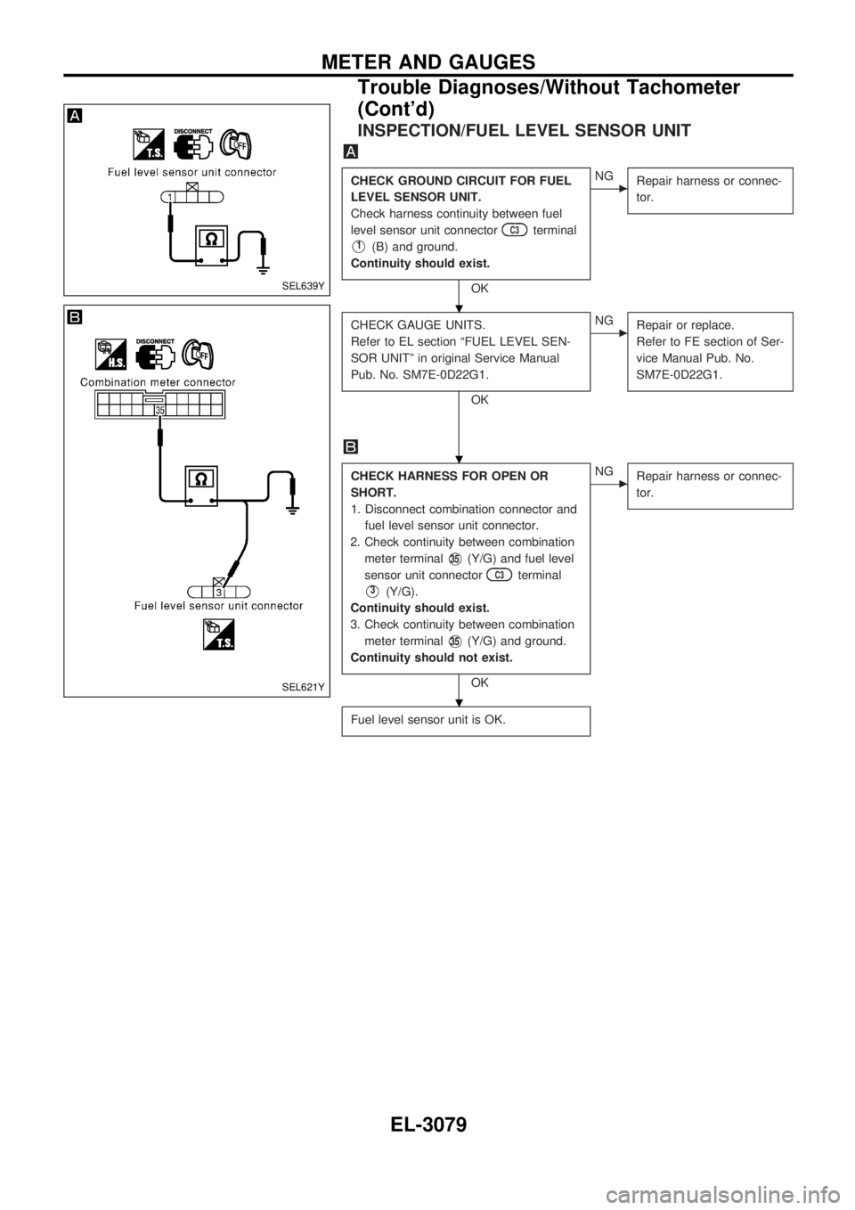
INSPECTION/FUEL LEVEL SENSOR UNIT
CHECK GROUND CIRCUIT FOR FUEL
LEVEL SENSOR UNIT.
Check harness continuity between fuel
level sensor unit connector
C3terminal
V1(B) and ground.
Continuity should exist.
OK
cNG
Repair harness or connec-
tor.
CHECK GAUGE UNITS.
Refer to EL section ªFUEL LEVEL SEN-
SOR UNITº in original Service Manual
Pub. No. SM7E-0D22G1.
OK
cNG
Repair or replace.
Refer to FE section of Ser-
vice Manual Pub. No.
SM7E-0D22G1.
CHECK HARNESS FOR OPEN OR
SHORT.
1. Disconnect combination connector and
fuel level sensor unit connector.
2. Check continuity between combination
meter terminal
V35(Y/G) and fuel level
sensor unit connector
C3terminal
V3(Y/G).
Continuity should exist.
3. Check continuity between combination
meter terminal
V35(Y/G) and ground.
Continuity should not exist.
OK
cNG
Repair harness or connec-
tor.
Fuel level sensor unit is OK.
SEL639Y
SEL621Y
.
.
.
METER AND GAUGES
Trouble Diagnoses/Without Tachometer
(Cont'd)
EL-3079
Page 755 of 1306
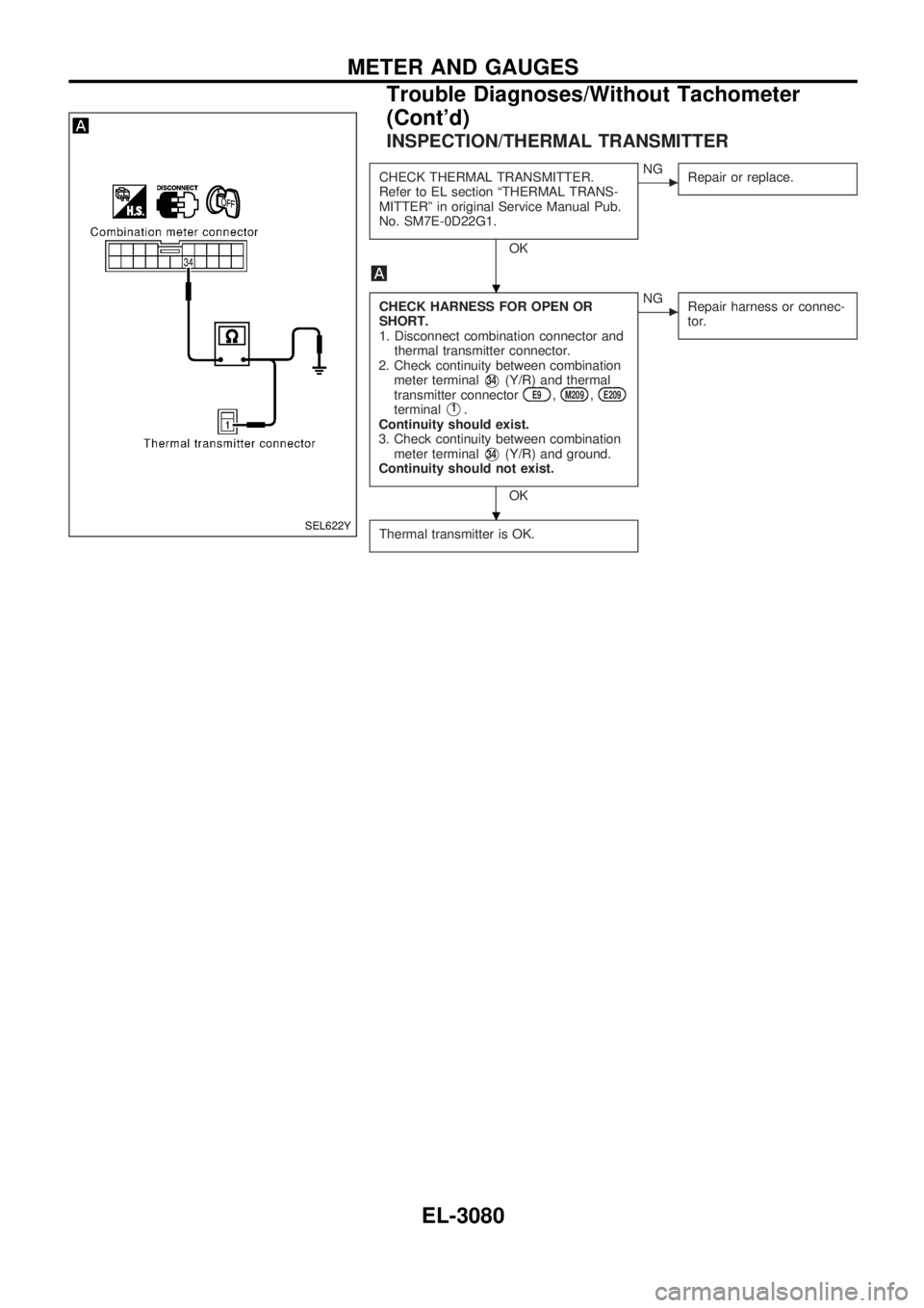
INSPECTION/THERMAL TRANSMITTER
CHECK THERMAL TRANSMITTER.
Refer to EL section ªTHERMAL TRANS-
MITTERº in original Service Manual Pub.
No. SM7E-0D22G1.
OK
cNG
Repair or replace.
CHECK HARNESS FOR OPEN OR
SHORT.
1. Disconnect combination connector and
thermal transmitter connector.
2. Check continuity between combination
meter terminal
V34(Y/R) and thermal
transmitter connectorE9,M209,E209terminalV1.
Continuity should exist.
3. Check continuity between combination
meter terminal
V34(Y/R) and ground.
Continuity should not exist.
OK
cNG
Repair harness or connec-
tor.
Thermal transmitter is OK.SEL622Y
.
.
METER AND GAUGES
Trouble Diagnoses/Without Tachometer
(Cont'd)
EL-3080
Page 812 of 1306
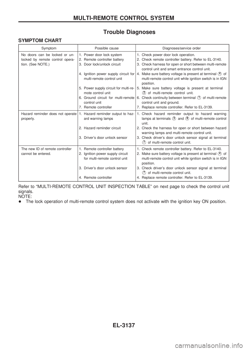
Trouble Diagnoses
SYMPTOM CHART
Symptom Possible cause Diagnoses/service order
No doors can be locked or un-
locked by remote control opera-
tion. (See NOTE.)1. Power door lock system
2. Remote controller battery
3. Door lock/unlock circuit
4. Ignition power supply circuit for
multi-remote control unit
5. Power supply circuit for multi-re-
mote control unit
6. Ground circuit for multi-remote
control unit
7. Remote controller1. Check power door lock operation.
2. Check remote controller battery. Refer to EL-3140.
3. Check harness for open or short between multi-remote
control unit and smart entrance control unit.
4. Make sure battery voltage is present at terminal
V4of
multi-remote control unit while ignition switch is in IGN
position.
5. Make sure battery voltage is present at terminal
V2of multi-remote control unit.
6. Check continuity between terminal
V1of multi-remote
control unit and ground.
7. Replace remote controller. Refer to EL-3139.
Hazard reminder does not operate
properly.1. Hazard reminder output to haz-
ard warning lamps
2. Hazard reminder circuit
3. Driver's door unlock sensor1. Check hazard reminder output to hazard warning
lamps at terminals
V3andV8of multi-remote control
unit.
2. Check the harness for open or short between hazard
warning lamps and multi-remote control unit.
3. Check driver's door unlock sensor signal at terminal
V7of multi-remote control unit.
The new ID of remote controller
cannot be entered.1. Remote controller battery
2. Ignition power supply circuit
for multi-remote control unit
3. Driver's door unlock sensor
4. Remote controller1. Check remote controller battery. Refer to EL-3140.
2. Make sure battery voltage is present at terminal
V4of
multi-remote control unit while ignition switch is in IGN
position.
3. Check driver's door unlock sensor signal at terminal
V7of multi-remote control unit.
4. Replace remote controller. Refer to EL-3139.
Refer to ªMULTI-REMOTE CONTROL UNIT INSPECTION TABLEº on next page to check the control unit
signals.
NOTE:
+The lock operation of multi-remote control system does not activate with the ignition key ON position.
MULTI-REMOTE CONTROL SYSTEM
EL-3137
Page 822 of 1306
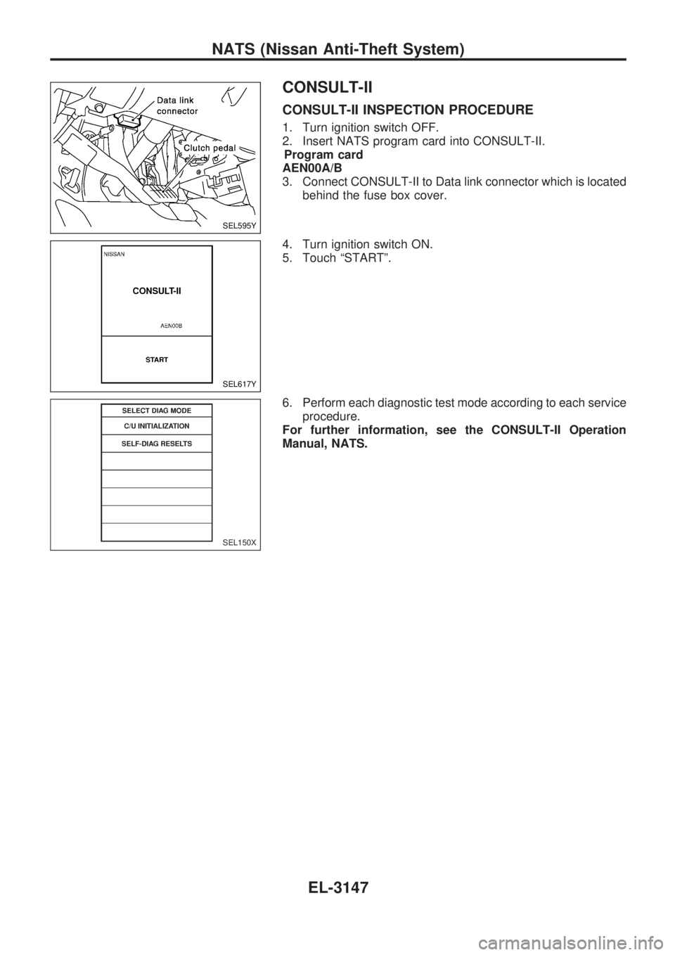
CONSULT-II
CONSULT-II INSPECTION PROCEDURE
1. Turn ignition switch OFF.
2. Insert NATS program card into CONSULT-II.
Program card
AEN00A/B
3. Connect CONSULT-II to Data link connector which is located
behind the fuse box cover.
4. Turn ignition switch ON.
5. Touch ªSTARTº.
6. Perform each diagnostic test mode according to each service
procedure.
For further information, see the CONSULT-II Operation
Manual, NATS.
SEL595Y
SEL617Y
SEL150X
NATS (Nissan Anti-Theft System)
EL-3147
Page 824 of 1306
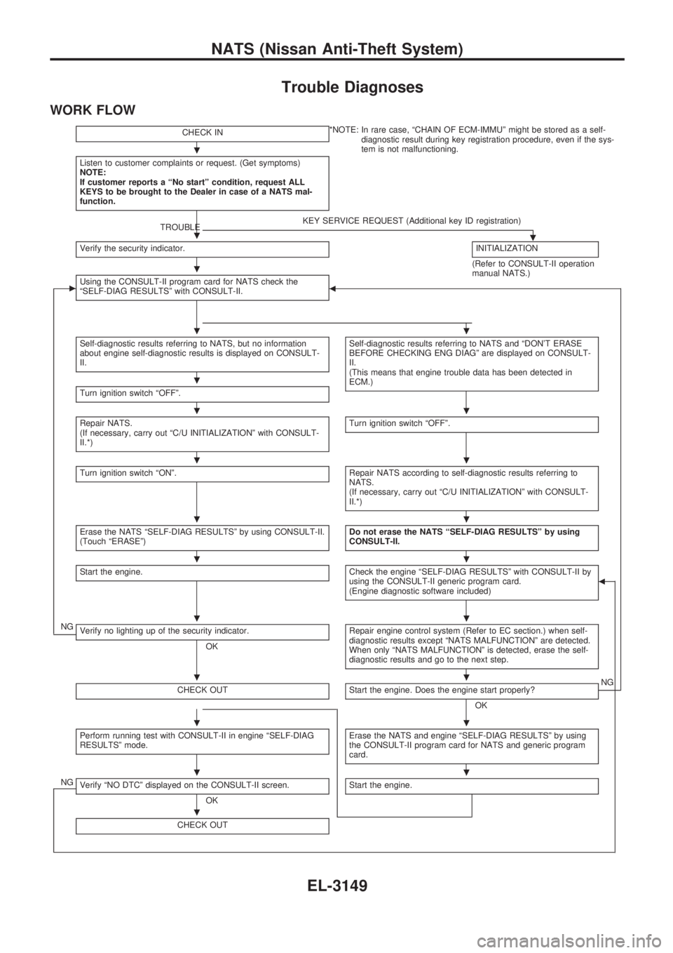
Trouble Diagnoses
WORK FLOW
CHECK IN*NOTE: In rare case, ªCHAIN OF ECM-IMMUº might be stored as a self-
diagnostic result during key registration procedure, even if the sys-
tem is not malfunctioning.
Listen to customer complaints or request. (Get symptoms)
NOTE:
If customer reports a ªNo startº condition, request ALL
KEYS to be brought to the Dealer in case of a NATS mal-
function.
TROUBLEKEY SERVICE REQUEST (Additional key ID registration).Verify the security indicator.INITIALIZATION
(Refer to CONSULT-II operation
manual NATS.)
cUsing the CONSULT-II program card for NATS check the
ªSELF-DIAG RESULTSº with CONSULT-II.b
Self-diagnostic results referring to NATS, but no information
about engine self-diagnostic results is displayed on CONSULT-
II.Self-diagnostic results referring to NATS and ªDON'T ERASE
BEFORE CHECKING ENG DIAGº are displayed on CONSULT-
II.
(This means that engine trouble data has been detected in
ECM.)
Turn ignition switch ªOFFº.
Repair NATS.
(If necessary, carry out ªC/U INITIALIZATIONº with CONSULT-
II.*)Turn ignition switch ªOFFº.
Turn ignition switch ªONº.Repair NATS according to self-diagnostic results referring to
NATS.
(If necessary, carry out ªC/U INITIALIZATIONº with CONSULT-
II.*)
Erase the NATS ªSELF-DIAG RESULTSº by using CONSULT-II.
(Touch ªERASEº)Do not erase the NATS ªSELF-DIAG RESULTSº by using
CONSULT-II.
Start the engine.Check the engine ªSELF-DIAG RESULTSº with CONSULT-II by
using the CONSULT-II generic program card.
(Engine diagnostic software included)b
NGVerify no lighting up of the security indicator.
OKRepair engine control system (Refer to EC section.) when self-
diagnostic results except ªNATS MALFUNCTIONº are detected.
When only ªNATS MALFUNCTIONº is detected, erase the self-
diagnostic results and go to the next step.
CHECK OUTStart the engine. Does the engine start properly?
OKNG
Perform running test with CONSULT-II in engine ªSELF-DIAG
RESULTSº mode.Erase the NATS and engine ªSELF-DIAG RESULTSº by using
the CONSULT-II program card for NATS and generic program
card.
NGVerify ªNO DTCº displayed on the CONSULT-II screen.
OKStart the engine.
CHECK OUT
.
.
.
..
.
..
..
..
..
..
..
..
..
.
NATS (Nissan Anti-Theft System)
EL-3149
Page 872 of 1306
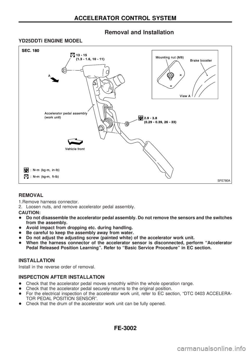
Removal and Installation
YD25DDTi ENGINE MODEL
REMOVAL
1.Remove harness connector.
2. Loosen nuts, and remove accelerator pedal assembly.
CAUTION:
+Do not disassemble the accelerator pedal assembly. Do not remove the sensors and the switches
from the assembly.
+Avoid impact from dropping etc. during handling.
+Be careful to keep the assembly away from water.
+Do not adjust the adjusting screw (painted white) of the accelerator work unit.
+When the harness connector of the accelerator sensor is disconnected, perform ªAccelerator
Pedal Released Position Learningº. Refer to ªBasic Service Procedureº in EC section.
INSTALLATION
Install in the reverse order of removal.
INSPECTION AFTER INSTALLATION
+Check that the accelerator pedal moves smoothly within the whole operation range.
+Check that the accelerator pedal securely returns to the original position.
+For the electrical inspection of the accelerator work unit, refer to EC section, ªDTC 0403 ACCELERA-
TOR PEDAL POSITION SENSORº.
+Check that the drum of the accelerator work unit can be fully opened.
SFE780A
ACCELERATOR CONTROL SYSTEM
FE-3002
Page 878 of 1306
ENGINE MECHANICAL
SECTION
EM
MODIFICATION NOTICE:
+KA24DE engine information has been added for Europe.
For information not included here, refer to information for KA24DE engine in D22 Supplement-II Service
Manual (SM9E-D22BE0E).
+YD25DDTi engine has newly been added.
CONTENTS
PRECAUTIONS................................................... 3003
Parts Requiring Angular Tightening................. 3003
Liquid Gasket Application Procedure .............. 3003
PREPARATION................................................... 3004
Special Service Tools (YD25DDTi engine) ..... 3004
Commercial Service Tools
(YD25DDTi engine).......................................... 3007
KA24DE
OUTER COMPONENT PARTS........................... 3008
YD25DDTi
NOISE, VIBRATION, AND HARSHNESS (NVH)
TROUBLESHOOTING......................................... 3011
NVH Troubleshooting - Engine Noise ............. 3011
MEASUREMENT OF COMPRESSION
PRESSURE.......................................................... 3013
CHARGE AIR COOLER...................................... 3014
Removal and Installation ................................. 3014
Inspection ......................................................... 3014
OIL PAN............................................................... 3015
Components ..................................................... 3015
Removal ........................................................... 3016
Installation ........................................................ 3018
TIMING CHAIN.................................................... 3021
Secondary Timing Chain ................................. 3021
Primary Timing Chain ...................................... 3026
INTAKE MANIFOLD............................................ 3035
Removal and Installation ................................. 3035
Inspection ......................................................... 3036
CATALYST.......................................................... 3037Removal and Installation ................................. 3037
EXHAUST MANIFOLD, TURBOCHARGER....... 3039
Removal and Installation ................................. 3039
Disassembly and Assembly ............................. 3041
Inspection ......................................................... 3041
ROCKER COVER................................................ 3045
Removal and Installation ................................. 3045
CYLINDER HEAD................................................ 3046
Components ..................................................... 3046
Removal ........................................................... 3047
Disassembly ..................................................... 3048
Inspection ......................................................... 3049
Assembly.......................................................... 3056
Installation ........................................................ 3056
Valve Clearance............................................... 3060
ENGINE REMOVAL............................................. 3063
Removal ........................................................... 3064
Installation ........................................................ 3065
Inspection ......................................................... 3065
CYLINDER BLOCK............................................. 3066
Components ..................................................... 3066
Removal and Installation ................................. 3067
Disassembly ..................................................... 3067
Inspection ......................................................... 3070
Assembly.......................................................... 3081
KA24DE
SERVICE DATA AND SPECIFICATIONS
(SDS).................................................................... 3086
Inspection and Adjustment .............................. 3086
EM