2001 NISSAN PICK-UP service
[x] Cancel search: servicePage 105 of 1306
SEF139P
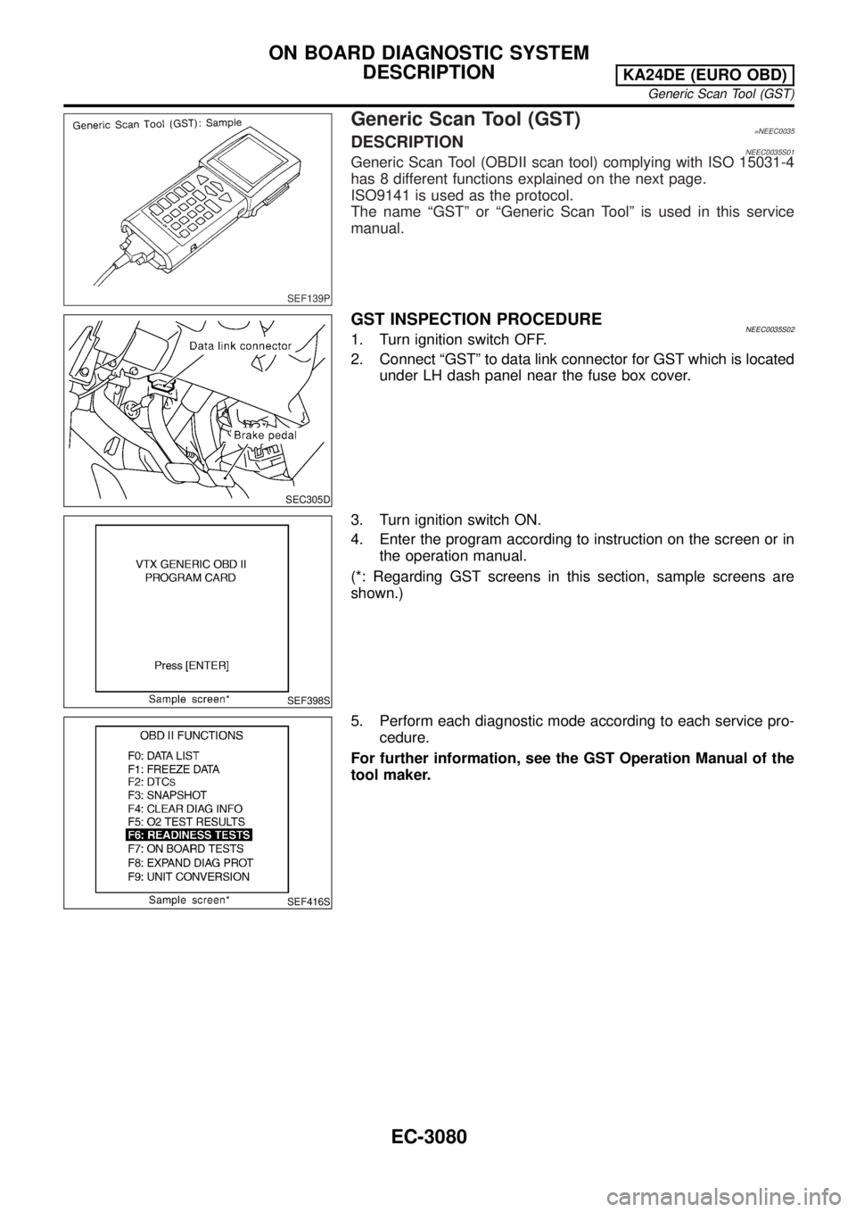
Generic Scan Tool (GST)=NEEC0035DESCRIPTIONNEEC0035S01Generic Scan Tool (OBDII scan tool) complying with ISO 15031-4
has 8 different functions explained on the next page.
ISO9141 is used as the protocol.
The name ªGSTº or ªGeneric Scan Toolº is used in this service
manual.
SEC305D
GST INSPECTION PROCEDURENEEC0035S021. Turn ignition switch OFF.
2. Connect ªGSTº to data link connector for GST which is located
under LH dash panel near the fuse box cover.
SEF398S
3. Turn ignition switch ON.
4. Enter the program according to instruction on the screen or in
the operation manual.
(*: Regarding GST screens in this section, sample screens are
shown.)
SEF416S
5. Perform each diagnostic mode according to each service pro-
cedure.
For further information, see the GST Operation Manual of the
tool maker.
ON BOARD DIAGNOSTIC SYSTEM
DESCRIPTION
KA24DE (EURO OBD)
Generic Scan Tool (GST)
EC-3080
Page 110 of 1306
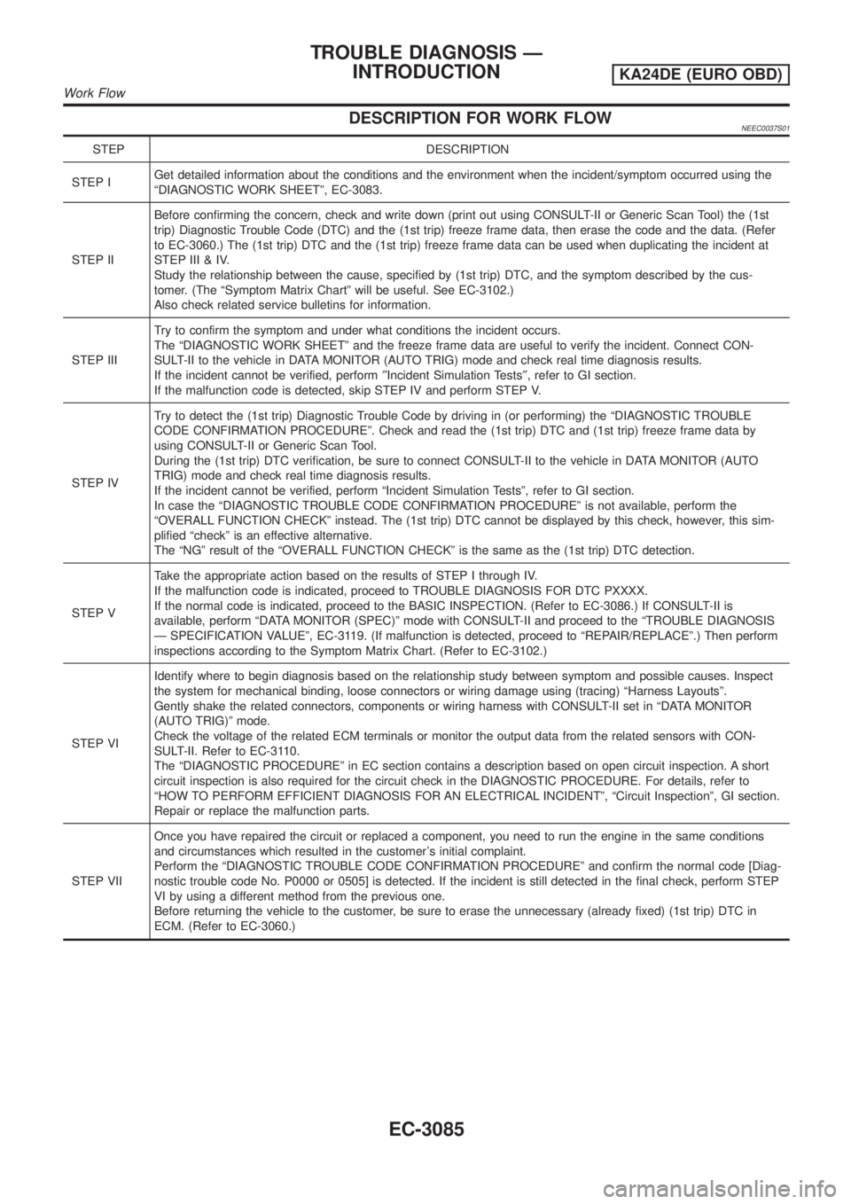
DESCRIPTION FOR WORK FLOWNEEC0037S01
STEP DESCRIPTION
STEP IGet detailed information about the conditions and the environment when the incident/symptom occurred using the
ªDIAGNOSTIC WORK SHEETº, EC-3083.
STEP IIBefore confirming the concern, check and write down (print out using CONSULT-II or Generic Scan Tool) the (1st
trip) Diagnostic Trouble Code (DTC) and the (1st trip) freeze frame data, then erase the code and the data. (Refer
to EC-3060.) The (1st trip) DTC and the (1st trip) freeze frame data can be used when duplicating the incident at
STEP III & IV.
Study the relationship between the cause, specified by (1st trip) DTC, and the symptom described by the cus-
tomer. (The ªSymptom Matrix Chartº will be useful. See EC-3102.)
Also check related service bulletins for information.
STEP IIITry to confirm the symptom and under what conditions the incident occurs.
The ªDIAGNOSTIC WORK SHEETº and the freeze frame data are useful to verify the incident. Connect CON-
SULT-II to the vehicle in DATA MONITOR (AUTO TRIG) mode and check real time diagnosis results.
If the incident cannot be verified, perform²Incident Simulation Tests², refer to GI section.
If the malfunction code is detected, skip STEP IV and perform STEP V.
STEP IVTry to detect the (1st trip) Diagnostic Trouble Code by driving in (or performing) the ªDIAGNOSTIC TROUBLE
CODE CONFIRMATION PROCEDUREº. Check and read the (1st trip) DTC and (1st trip) freeze frame data by
using CONSULT-II or Generic Scan Tool.
During the (1st trip) DTC verification, be sure to connect CONSULT-II to the vehicle in DATA MONITOR (AUTO
TRIG) mode and check real time diagnosis results.
If the incident cannot be verified, perform ªIncident Simulation Testsº, refer to GI section.
In case the ªDIAGNOSTIC TROUBLE CODE CONFIRMATION PROCEDUREº is not available, perform the
ªOVERALL FUNCTION CHECKº instead. The (1st trip) DTC cannot be displayed by this check, however, this sim-
plified ªcheckº is an effective alternative.
The ªNGº result of the ªOVERALL FUNCTION CHECKº is the same as the (1st trip) DTC detection.
STEP VTake the appropriate action based on the results of STEP I through IV.
If the malfunction code is indicated, proceed to TROUBLE DIAGNOSIS FOR DTC PXXXX.
If the normal code is indicated, proceed to the BASIC INSPECTION. (Refer to EC-3086.) If CONSULT-II is
available, perform ªDATA MONITOR (SPEC)º mode with CONSULT-II and proceed to the ªTROUBLE DIAGNOSIS
Ð SPECIFICATION VALUEº, EC-3119. (If malfunction is detected, proceed to ªREPAIR/REPLACEº.) Then perform
inspections according to the Symptom Matrix Chart. (Refer to EC-3102.)
STEP VIIdentify where to begin diagnosis based on the relationship study between symptom and possible causes. Inspect
the system for mechanical binding, loose connectors or wiring damage using (tracing) ªHarness Layoutsº.
Gently shake the related connectors, components or wiring harness with CONSULT-II set in ªDATA MONITOR
(AUTO TRIG)º mode.
Check the voltage of the related ECM terminals or monitor the output data from the related sensors with CON-
SULT-II. Refer to EC-3110.
The ªDIAGNOSTIC PROCEDUREº in EC section contains a description based on open circuit inspection. A short
circuit inspection is also required for the circuit check in the DIAGNOSTIC PROCEDURE. For details, refer to
ªHOW TO PERFORM EFFICIENT DIAGNOSIS FOR AN ELECTRICAL INCIDENTº, ªCircuit Inspectionº, GI section.
Repair or replace the malfunction parts.
STEP VIIOnce you have repaired the circuit or replaced a component, you need to run the engine in the same conditions
and circumstances which resulted in the customer's initial complaint.
Perform the ªDIAGNOSTIC TROUBLE CODE CONFIRMATION PROCEDUREº and confirm the normal code [Diag-
nostic trouble code No. P0000 or 0505] is detected. If the incident is still detected in the final check, perform STEP
VI by using a different method from the previous one.
Before returning the vehicle to the customer, be sure to erase the unnecessary (already fixed) (1st trip) DTC in
ECM. (Refer to EC-3060.)
TROUBLE DIAGNOSIS Ð
INTRODUCTION
KA24DE (EURO OBD)
Work Flow
EC-3085
Page 111 of 1306

Basic InspectionNEEC0038Precaution:
Perform Basic Inspection without electrical or mechanical
loads applied;
+Headlamp switch is OFF,
+Air conditioner switch is OFF,
+Rear window defogger switch is OFF,
+Steering wheel is in the straight-ahead position, etc.
1 INSPECTION START
1. Check service records for any recent repairs that may indicate a related problem, or the current need for scheduled
maintenance.
2. Open engine hood and check the following:
+Harness connectors for improper connections
+Vacuum hoses for splits, kinks, or improper connections
+Wiring for improper connections, pinches, or cuts
SEF142I
With CONSULT-II©GO TO 2.
With GST©GO TO 4.
No tools©GO TO 5.
2 CONNECT CONSULT-II TO THE VEHICLE
Connect ªCONSULT-IIº to the data link connector and select ªENGINEº from the menu. Refer to EC-3070.
SEC305D
©GO TO 3.
TROUBLE DIAGNOSIS Ð BASIC
INSPECTION
KA24DE (EURO OBD)
Basic Inspection
EC-3086
Page 423 of 1306
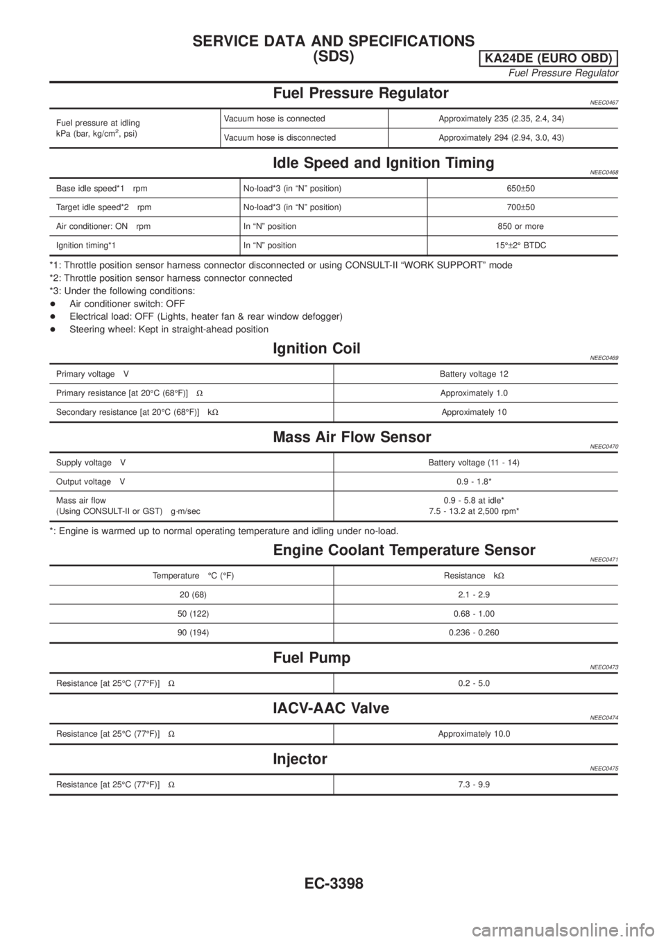
Fuel Pressure RegulatorNEEC0467
Fuel pressure at idling
kPa (bar, kg/cm2, psi)Vacuum hose is connected Approximately 235 (2.35, 2.4, 34)
Vacuum hose is disconnected Approximately 294 (2.94, 3.0, 43)
Idle Speed and Ignition TimingNEEC0468
Base idle speed*1 rpm No-load*3 (in ªNº position) 650±50
Target idle speed*2 rpm No-load*3 (in ªNº position) 700±50
Air conditioner: ON rpm In ªNº position 850 or more
Ignition timing*1 In ªNº position 15ɱ2É BTDC
*1: Throttle position sensor harness connector disconnected or using CONSULT-II ªWORK SUPPORTº mode
*2: Throttle position sensor harness connector connected
*3: Under the following conditions:
+Air conditioner switch: OFF
+Electrical load: OFF (Lights, heater fan & rear window defogger)
+Steering wheel: Kept in straight-ahead position
Ignition CoilNEEC0469
Primary voltage VBattery voltage 12
Primary resistance [at 20ÉC (68ÉF)]WApproximately 1.0
Secondary resistance [at 20ÉC (68ÉF)] kWApproximately 10
Mass Air Flow SensorNEEC0470
Supply voltage VBattery voltage (11 - 14)
Output voltage V0.9 - 1.8*
Mass air flow
(Using CONSULT-II or GST) g´m/sec0.9 - 5.8 at idle*
7.5 - 13.2 at 2,500 rpm*
*: Engine is warmed up to normal operating temperature and idling under no-load.
Engine Coolant Temperature SensorNEEC0471
Temperature ÉC (ÉF) Resistance kW
20 (68) 2.1 - 2.9
50 (122) 0.68 - 1.00
90 (194) 0.236 - 0.260
Fuel PumpNEEC0473
Resistance [at 25ÉC (77ÉF)]W0.2 - 5.0
IACV-AAC ValveNEEC0474
Resistance [at 25ÉC (77ÉF)]WApproximately 10.0
InjectorNEEC0475
Resistance [at 25ÉC (77ÉF)]W7.3 - 9.9
SERVICE DATA AND SPECIFICATIONS
(SDS)
KA24DE (EURO OBD)
Fuel Pressure Regulator
EC-3398
Page 424 of 1306
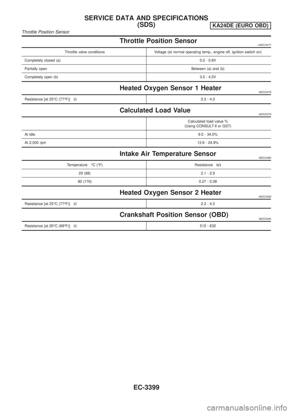
Throttle Position Sensor=NEEC0477
Throttle valve conditions Voltage (at normal operating temp., engine off, ignition switch on)
Completely closed (a)0.2 - 0.8V
Partially openBetween (a) and (b)
Completely open (b)3.5 - 4.5V
Heated Oxygen Sensor 1 HeaterNEEC0478
Resistance [at 25ÉC (77ÉF)]W2.3 - 4.3
Calculated Load ValueNEEC0479
Calculated load value %
(Using CONSULT-II or GST)
At idle9.5 - 34.0%
At 2,500 rpm13.9 - 24.9%
Intake Air Temperature SensorNEEC0480
Temperature ÉC (ÉF) Resistance kW
20 (68) 2.1 - 2.9
80 (176) 0.27 - 0.38
Heated Oxygen Sensor 2 HeaterNEEC0483
Resistance [at 25ÉC (77ÉF)]W2.3 - 4.3
Crankshaft Position Sensor (OBD)NEEC0484
Resistance [at 20ÉC (68ÉF)]W512 - 632
SERVICE DATA AND SPECIFICATIONS
(SDS)
KA24DE (EURO OBD)
Throttle Position Sensor
EC-3399
Page 440 of 1306
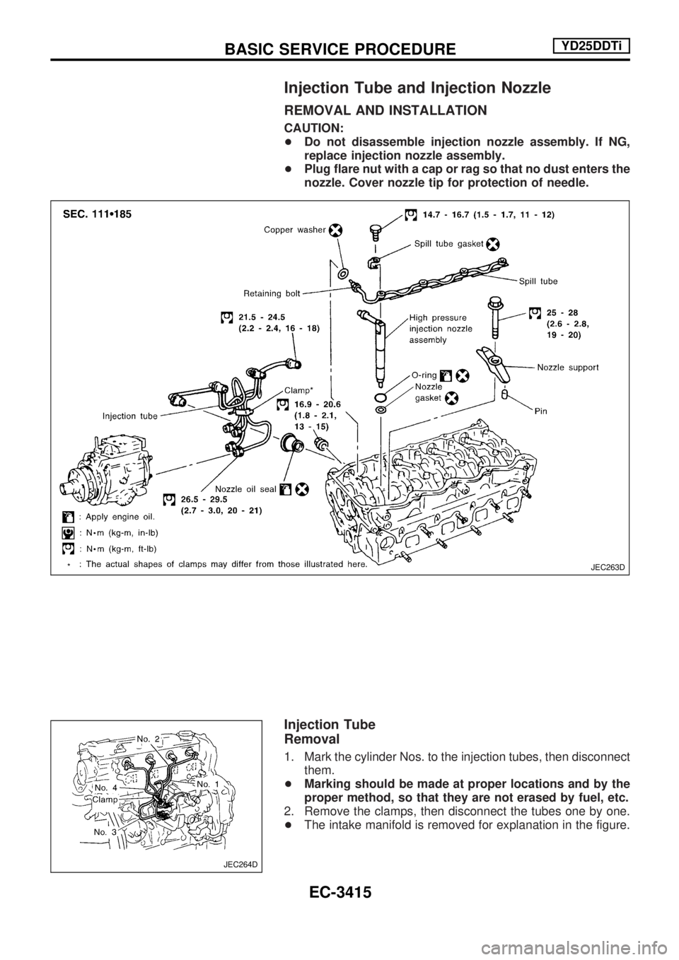
Injection Tube and Injection Nozzle
REMOVAL AND INSTALLATION
CAUTION:
+Do not disassemble injection nozzle assembly. If NG,
replace injection nozzle assembly.
+Plug flare nut with a cap or rag so that no dust enters the
nozzle. Cover nozzle tip for protection of needle.
Injection Tube
Removal
1. Mark the cylinder Nos. to the injection tubes, then disconnect
them.
+Marking should be made at proper locations and by the
proper method, so that they are not erased by fuel, etc.
2. Remove the clamps, then disconnect the tubes one by one.
+The intake manifold is removed for explanation in the figure.
JEC263D
JEC264D
BASIC SERVICE PROCEDUREYD25DDTi
EC-3415
Page 441 of 1306
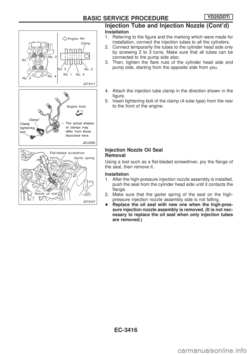
Installation
1. Referring to the figure and the marking which were made for
installation, connect the injection tubes to all the cylinders.
2. Connect temporarily the tubes to the cylinder head side only
by screwing 2 to 3 turns. Make sure that all tubes can be
connected to the pump side also.
3. Then, tighten the flare nuts of the cylinder head side and
pump side, starting from the opposite side from you.
4. Attach the injection tube clamp in the direction shown in the
figure.
5. Insert tightening bolt of the clamp (4-tube type) from the rear
to the front of the engine.
Injection Nozzle Oil Seal
Removal
Using a tool such as a flat-bladed screwdriver, pry the flange of
the seal, then remove it.
Installation
1. After the high-pressure injection nozzle assembly is installed,
push the seal from the cylinder head side until it contacts the
flange.
2. Make sure that the garter spring of the seal on the high-
pressure injection nozzle assembly side is not falling.
+Replace the oil seal with new one when the high-pres-
sure injection nozzle assembly is removed. (It is not nec-
essary to replace the oil seal when only injection tubes
are removed.)
JEF341Y
JEC335D
JEF343Y
BASIC SERVICE PROCEDUREYD25DDTi
Injection Tube and Injection Nozzle (Cont'd)
EC-3416
Page 442 of 1306
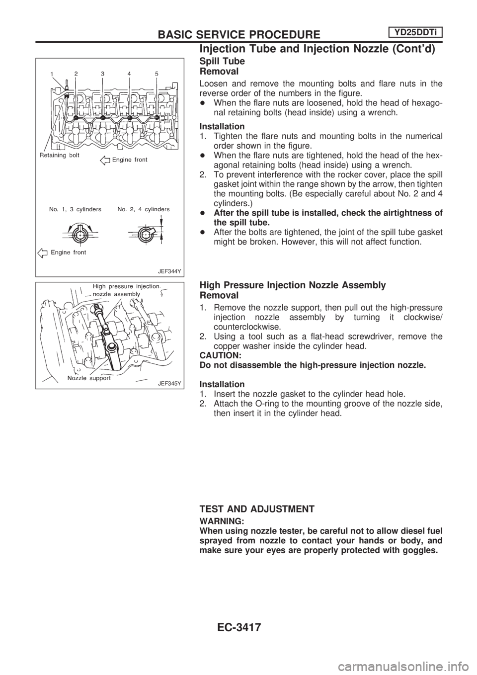
Spill Tube
Removal
Loosen and remove the mounting bolts and flare nuts in the
reverse order of the numbers in the figure.
+When the flare nuts are loosened, hold the head of hexago-
nal retaining bolts (head inside) using a wrench.
Installation
1. Tighten the flare nuts and mounting bolts in the numerical
order shown in the figure.
+When the flare nuts are tightened, hold the head of the hex-
agonal retaining bolts (head inside) using a wrench.
2. To prevent interference with the rocker cover, place the spill
gasket joint within the range shown by the arrow, then tighten
the mounting bolts. (Be especially careful about No. 2 and 4
cylinders.)
+After the spill tube is installed, check the airtightness of
the spill tube.
+After the bolts are tightened, the joint of the spill tube gasket
might be broken. However, this will not affect function.
High Pressure Injection Nozzle Assembly
Removal
1. Remove the nozzle support, then pull out the high-pressure
injection nozzle assembly by turning it clockwise/
counterclockwise.
2. Using a tool such as a flat-head screwdriver, remove the
copper washer inside the cylinder head.
CAUTION:
Do not disassemble the high-pressure injection nozzle.
Installation
1. Insert the nozzle gasket to the cylinder head hole.
2. Attach the O-ring to the mounting groove of the nozzle side,
then insert it in the cylinder head.
TEST AND ADJUSTMENT
WARNING:
When using nozzle tester, be careful not to allow diesel fuel
sprayed from nozzle to contact your hands or body, and
make sure your eyes are properly protected with goggles.
JEF344Y
JEF345Y
BASIC SERVICE PROCEDUREYD25DDTi
Injection Tube and Injection Nozzle (Cont'd)
EC-3417