Page 624 of 1306
Diagnostic Procedure
1 INSPECTION START
With CONSULT-II
1. Turn ignition switch ªONº.
2. Select ªSELF DIAG RESULTSº mode with CONSULT-II.
3. Touch ªERASEº.
4. Perform ªDTC Confirmation Procedureº, EC-3598, again.
5. Is the malfunction displayed again?
Without CONSULT-II
1. Turn ignition switch ªONº.
2. Erase the Diagnostic Test Mode II (Self-diagnostic results) memory.
3. Perform ªDTC Confirmation Procedureº, EC-3598, again.
4. Perform ªDiagnostic Test Mode II (Self-diagnostic results)º.
5. Is the DTC 0903 displayed again?
Yes or No
YescGO TO 2.
NocINSPECTION END
2 REPLACE ECM
1. Replace ECM.
2. Perform intialization of NATS system and registration of all NATS ignition key IDs. Refer to EC-3429. (Models with NATS)
3. Perform ªAccelerator Position Sensor Idle Position Learningº of ªBASIC SERVICE PROCEDUREº. Refer to EC-3427.
cINSPECTION END
DTC 0903 ECM 15YD25DDTi
EC-3599
Page 675 of 1306

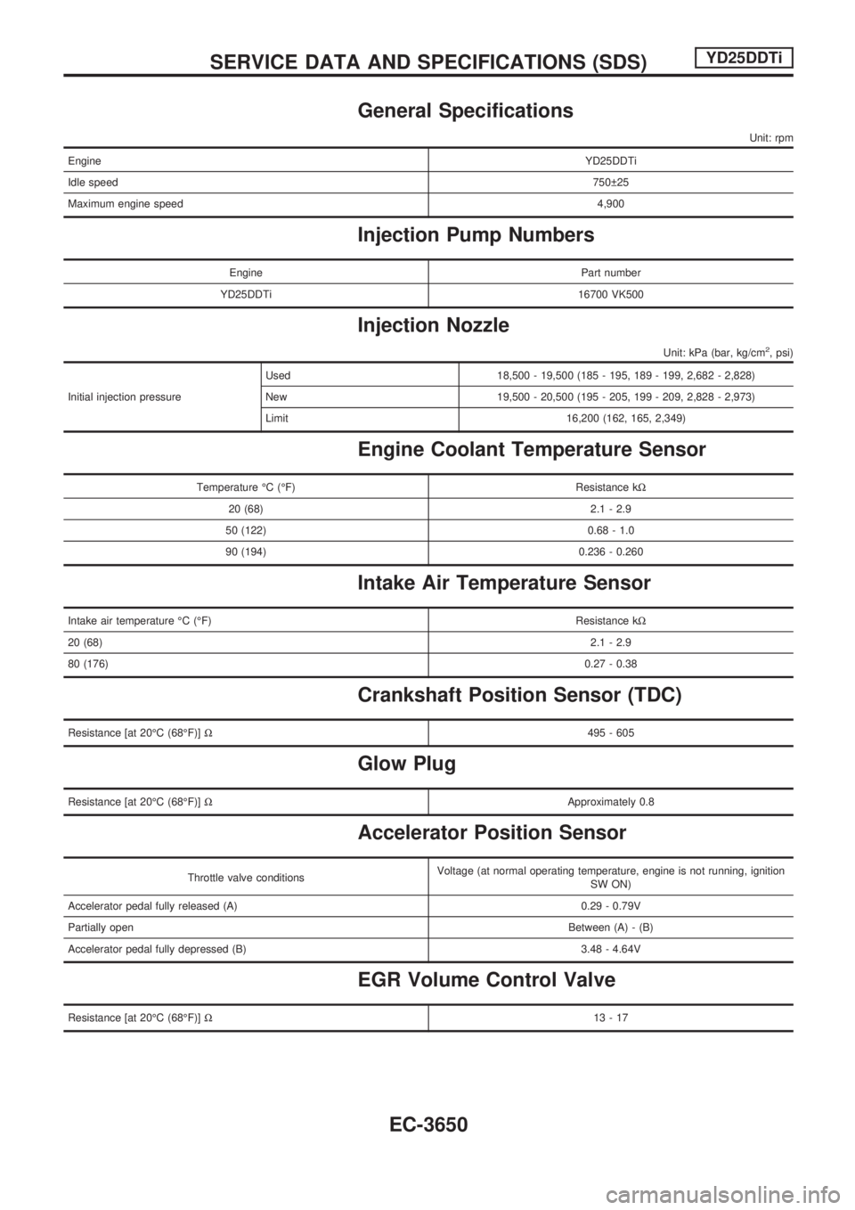
General Specifications
Unit: rpm
EngineYD25DDTi
Idle speed750 25
Maximum engine speed4,900
Injection Pump Numbers
Engine Part number
YD25DDTi 16700 VK500
Injection Nozzle
Unit: kPa (bar, kg/cm2, psi)
Initial injection pressureUsed 18,500 - 19,500 (185 - 195, 189 - 199, 2,682 - 2,828)
New 19,500 - 20,500 (195 - 205, 199 - 209, 2,828 - 2,973)
Limit 16,200 (162, 165, 2,349)
Engine Coolant Temperature Sensor
Temperature ÉC (ÉF) Resistance kW
20 (68) 2.1 - 2.9
50 (122) 0.68 - 1.0
90 (194) 0.236 - 0.260
Intake Air Temperature Sensor
Intake air temperature ÉC (ÉF)Resistance kW
20 (68)2.1 - 2.9
80 (176)0.27 - 0.38
Crankshaft Position Sensor (TDC)
Resistance [at 20ÉC (68ÉF)]W495 - 605
Glow Plug
Resistance [at 20ÉC (68ÉF)]WApproximately 0.8
Accelerator Position Sensor
Throttle valve conditionsVoltage (at normal operating temperature, engine is not running, ignition
SW ON)
Accelerator pedal fully released (A) 0.29 - 0.79V
Partially openBetween (A) - (B)
Accelerator pedal fully depressed (B) 3.48 - 4.64V
EGR Volume Control Valve
Resistance [at 20ÉC (68ÉF)]W13-17
SERVICE DATA AND SPECIFICATIONS (SDS)YD25DDTi
EC-3650
Page 676 of 1306

ELECTRICAL SYSTEM
SECTION
EL
MODIFICATION NOTICE:
+Wiring diagrams have been changed.
+Combination meter has been changed.
+Headlamp has been changed.
+Headlamp aiming control has been added.
+Headlamp washer has been added.
+A hazard reminder feature has been added to the multi-remote control system.
+NATS (Nissan Anti-Theft System) has been changed.
CONTENTS
PRECAUTIONS................................................... 3004
Supplemental Restraint System (SRS)²AIR
BAG²and²SEAT BELT PRE-TENSIONER².. 3004
POWER SUPPLY ROUTING............................... 3005
Schematic ........................................................ 3005
Wiring Diagram - POWER -............................. 3006
BATTERY............................................................. 3013
Service Data and Specifications (SDS) ........... 3013
STARTING SYSTEM........................................... 3014
Wiring Diagram - START -/M/T Models .......... 3014
Construction ..................................................... 3015
Service Data and Specifications (SDS) ........... 3017
CHARGING SYSTEM.......................................... 3018
Wiring Diagram - CHARGE -/Diesel Engine ... 3018
Wiring Diagram - CHARGE - (KA engine) ...... 3019
Construction ..................................................... 3020
Service Data and Specifications (SDS) ........... 3022
HEADLAMP - Conventional Type -................... 3023
Wiring Diagram - H/LAMP -/LHD Models ........ 3023
Wiring Diagram - H/LAMP -/RHD Models ....... 3025
Bulb Replacement............................................ 3027
Aiming Adjustment ........................................... 3027
Low Beam ........................................................ 3028
HEADLAMP - Daytime Light System -............. 3029
Wiring Diagram - DTRL - ................................. 3029
Bulb Replacement............................................ 3032
Aiming Adjustment ........................................... 3032
HEADLAMP - Dim-dip Lamp System -............. 3033Wiring Diagram - DIMDIP -.............................. 3033
Bulb Replacement............................................ 3036
Aiming Adjustment ........................................... 3036
HEADLAMP - Headlamp Aiming Control -....... 3037
Wiring Diagram - H/AIM - ................................ 3037
PARKING, LICENSE AND TAIL LAMPS........... 3039
Wiring Diagram - TAIL/L -/Except LHD Models
for Europe ........................................................ 3039
Wiring Diagram - TAIL/L -/LHD Models for
Europe.............................................................. 3041
STOP LAMP........................................................ 3043
Wiring Diagram - STOP/L - ............................. 3043
BACK-UP LAMP.................................................. 3044
Wiring Diagram - BACK/L -/M/T Models ......... 3044
REAR FOG LAMP............................................... 3045
Wiring Diagram - R/FOG -/LHD Models .......... 3045
Wiring Diagram - R/FOG -/RHD Models ......... 3046
TURN SIGNAL AND HAZARD WARNING
LAMPS................................................................. 3047
Wiring Diagram - TURN - ................................ 3047
Trouble Diagnoses ........................................... 3049
ILLUMINATION.................................................... 3050
Wiring Diagram - ILL -/LHD Models ................ 3050
Wiring Diagram - ILL -/RHD Models................ 3052
INTERIOR ROOM LAMP..................................... 3054
Wiring Diagram - ROOM/L - ............................ 3054
SPOT LAMP........................................................ 3055
Wiring Diagram - INT/L - ................................. 3055
EL
Page 679 of 1306

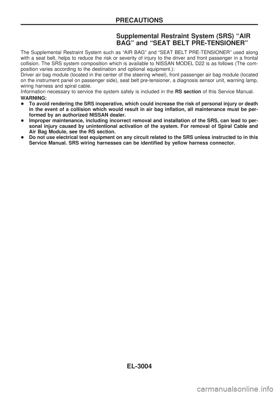
Supplemental Restraint System (SRS) ªAIR
BAGº and ªSEAT BELT PRE-TENSIONERº
The Supplemental Restraint System such as ªAIR BAGº and ªSEAT BELT PRE-TENSIONERº used along
with a seat belt, helps to reduce the risk or severity of injury to the driver and front passenger in a frontal
collision. The SRS system composition which is available to NISSAN MODEL D22 is as follows (The com-
position varies according to the destination and optional equipment.):
Driver air bag module (located in the center of the steering wheel), front passenger air bag module (located
on the instrument panel on passenger side), seat belt pre-tensioner, a diagnosis sensor unit, warning lamp,
wiring harness and spiral cable.
Information necessary to service the system safely is included in theRS sectionof this Service Manual.
WARNING:
+To avoid rendering the SRS inoperative, which could increase the risk of personal injury or death
in the event of a collision which would result in air bag inflation, all maintenance must be per-
formed by an authorized NISSAN dealer.
+Improper maintenance, including incorrect removal and installation of the SRS, can lead to per-
sonal injury caused by unintentional activation of the system. For removal of Spiral Cable and
Air Bag Module, see the RS section.
+Do not use electrical test equipment on any circuit related to the SRS unless instructed to in this
Service Manual. SRS wiring harnesses can be identified by yellow harness connector.
PRECAUTIONS
EL-3004
Page 688 of 1306
Service Data and Specifications (SDS)
Applied modelEurope
YD25
Standard
Type110D26R
Capacity V-AH 12-64
BATTERY
EL-3013
Page 692 of 1306

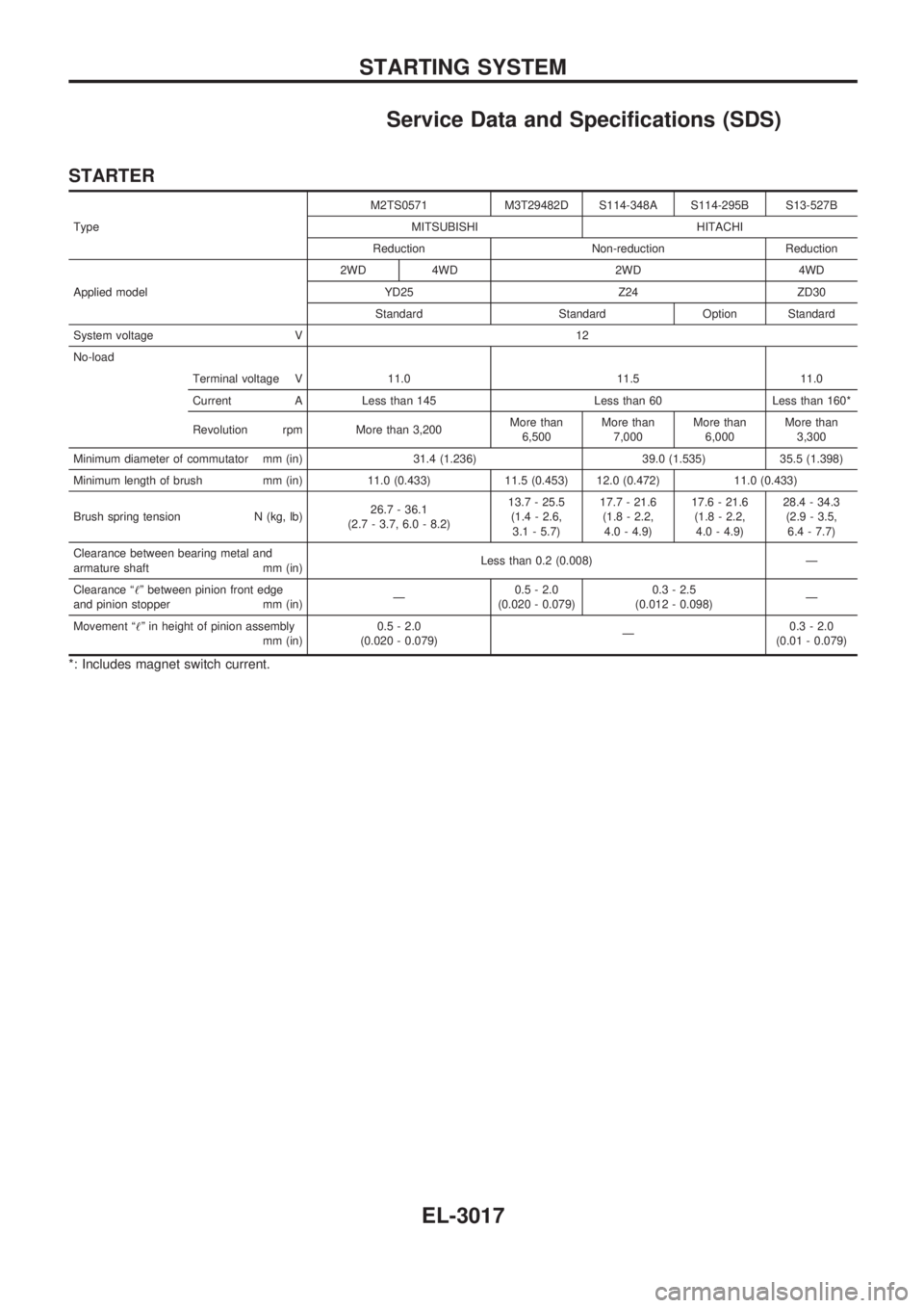
Service Data and Specifications (SDS)
STARTER
TypeM2TS0571 M3T29482D S114-348A S114-295B S13-527B
MITSUBISHI HITACHI
Reduction Non-reduction Reduction
Applied model2WD 4WD 2WD 4WD
YD25 Z24 ZD30
Standard Standard Option Standard
System voltage V 12
No-load
Terminal voltage V 11.0 11.5 11.0
Current A Less than 145 Less than 60 Less than 160*
Revolution rpm More than 3,200More than
6,500More than
7,000More than
6,000More than
3,300
Minimum diameter of commutator mm (in) 31.4 (1.236) 39.0 (1.535) 35.5 (1.398)
Minimum length of brush mm (in) 11.0 (0.433) 11.5 (0.453) 12.0 (0.472) 11.0 (0.433)
Brush spring tension N (kg, lb)26.7 - 36.1
(2.7 - 3.7, 6.0 - 8.2)13.7 - 25.5
(1.4 - 2.6,
3.1 - 5.7)17.7 - 21.6
(1.8 - 2.2,
4.0 - 4.9)17.6 - 21.6
(1.8 - 2.2,
4.0 - 4.9)28.4 - 34.3
(2.9 - 3.5,
6.4 - 7.7)
Clearance between bearing metal and
armature shaft mm (in)Less than 0.2 (0.008) Ð
Clearance ª!º between pinion front edge
and pinion stopper mm (in)Ð0.5 - 2.0
(0.020 - 0.079)0.3 - 2.5
(0.012 - 0.098)Ð
Movement ª!º in height of pinion assembly
mm (in)0.5 - 2.0
(0.020 - 0.079)Ð0.3 - 2.0
(0.01 - 0.079)
*: Includes magnet switch current.
STARTING SYSTEM
EL-3017
Page 697 of 1306

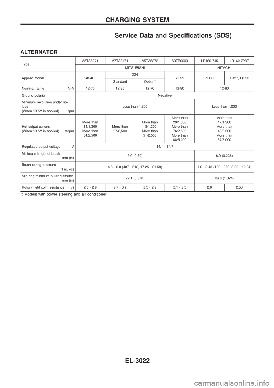
Service Data and Specifications (SDS)
ALTERNATOR
TypeA5TA5271 A7TA8471 A5TA5372 A3TB0699 LR160-745 LR160-728E
MITSUBISHI HITACHI
Applied model KA24DEZ24
YD25 ZD30 TD27, QD32
Standard Option*
Nominal rating V-A 12-70 12-35 12-70 12-90 12-60
Ground polarityNegative
Minimum revolution under no-
load
(When 13.5V is applied) rpmLess than 1,300 Less than 1,000
Hot output current
(When 13.5V is applied) A/rpmMore than
14/1,300
More than
54/2,500More than
27/2,500More than
18/1,300
More than
51/2,500More than
29/1,300
More than
76/2,500
More than
88/5,000More than
17/1,300
More than
48/2,500
More than
57/5,000
Regulated output voltage V 14.1 - 14.7
Minimum length of brush
mm (in)5.0 (0.20) 6.0 (0.236)
Brush spring pressure
N (g, oz)4.8 - 6.0 (487 - 612, 17.25 - 21.59) 1.0 - 3.43 (102 - 350, 3.60 - 12.34)
Slip ring minimum outer diameter
mm (in)22.1 (0.870) 26.0 (1.024)
Rotor (Field coil) resistanceW2.5 - 2.9 2.7 - 3.2 2.5 - 2.9 2.1 - 2.5 2.6 2.58
*: Models with power steering and air conditioner
CHARGING SYSTEM
EL-3022
Page 749 of 1306
INSPECTION/FUEL LEVEL SENSOR UNIT
CHECK GROUND CIRCUIT FOR FUEL
LEVEL SENSOR UNIT.
Check harness continuity between fuel
level sensor unit connector
C3terminal
V1(B) and ground.
Continuity should exist.
OK
cNG
Repair harness or connec-
tor.
CHECK GAUGE UNITS.
Refer to EL section ªFUEL LEVEL SEN-
SOR UNITº in original Service Manual
Pub. No. SM7E-0D22G1.
OK
cNG
Repair or replace.
Refer to FE section of Ser-
vice Manual Pub. No.
SM7E-0D22G1.
CHECK HARNESS FOR OPEN OR
SHORT.
1. Disconnect combination connector and
fuel level sensor unit connector.
2. Check continuity between combination
meter terminal
V20(Y/G) and fuel level
sensor unit connector
C3terminal
V3(Y/G).
Continuity should exist.
3. Check continuity between combination
meter terminal
V20(Y/G) and ground.
Continuity should not exist.
OK
cNG
Repair harness or connec-
tor.
Fuel level sensor unit is OK.
SEL639Y
SEL409Y
.
.
.
METER AND GAUGES
Trouble Diagnoses/With Tachometer (Cont'd)
EL-3074