Page 33 of 1306

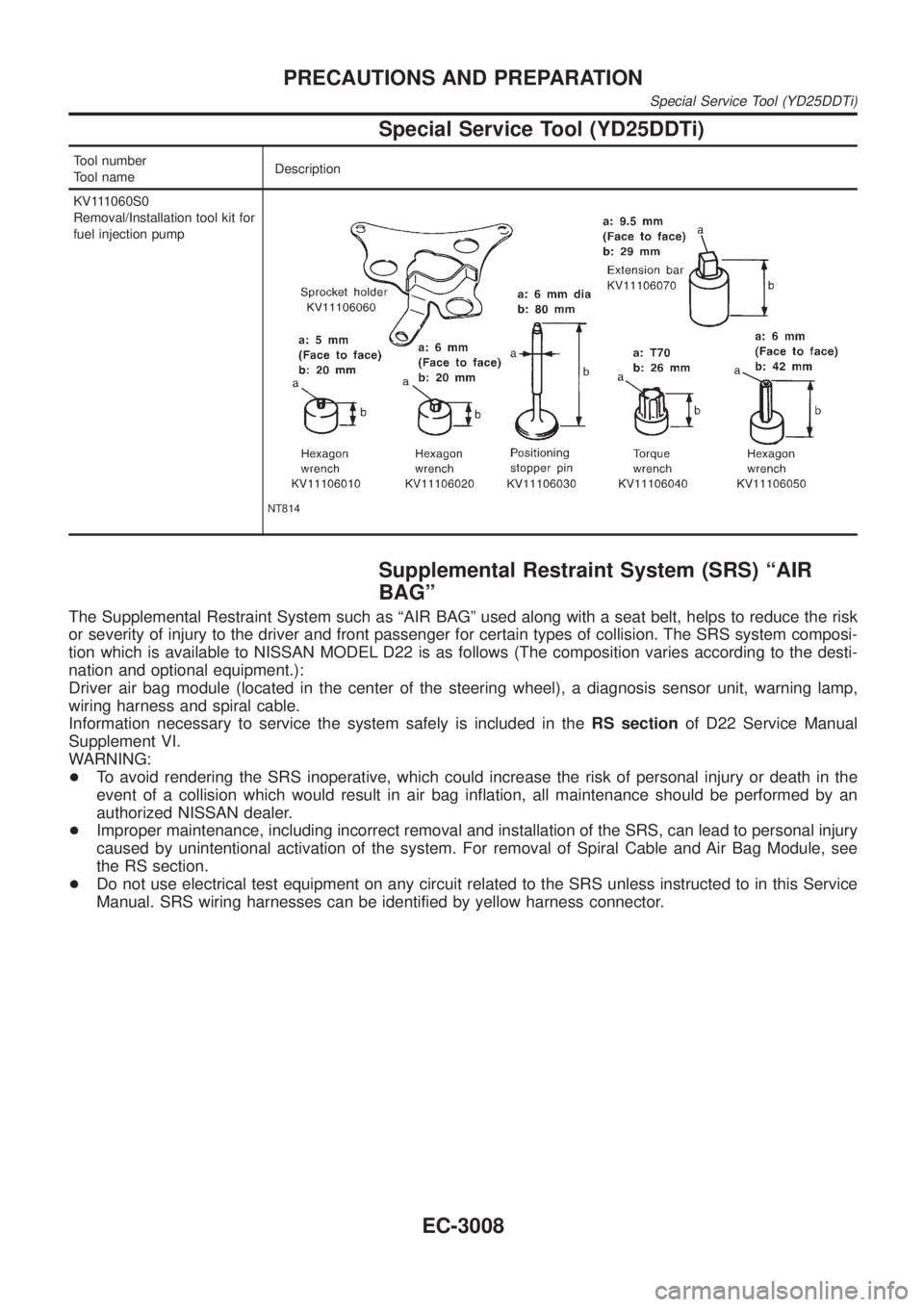
Special Service Tool (YD25DDTi)
Tool number
Tool nameDescription
KV111060S0
Removal/Installation tool kit for
fuel injection pump
NT814
Supplemental Restraint System (SRS) ªAIR
BAGº
The Supplemental Restraint System such as ªAIR BAGº used along with a seat belt, helps to reduce the risk
or severity of injury to the driver and front passenger for certain types of collision. The SRS system composi-
tion which is available to NISSAN MODEL D22 is as follows (The composition varies according to the desti-
nation and optional equipment.):
Driver air bag module (located in the center of the steering wheel), a diagnosis sensor unit, warning lamp,
wiring harness and spiral cable.
Information necessary to service the system safely is included in theRS sectionof D22 Service Manual
Supplement VI.
WARNING:
+To avoid rendering the SRS inoperative, which could increase the risk of personal injury or death in the
event of a collision which would result in air bag inflation, all maintenance should be performed by an
authorized NISSAN dealer.
+Improper maintenance, including incorrect removal and installation of the SRS, can lead to personal injury
caused by unintentional activation of the system. For removal of Spiral Cable and Air Bag Module, see
the RS section.
+Do not use electrical test equipment on any circuit related to the SRS unless instructed to in this Service
Manual. SRS wiring harnesses can be identified by yellow harness connector.
PRECAUTIONS AND PREPARATION
Special Service Tool (YD25DDTi)
EC-3008
Page 37 of 1306

Supplemental Restraint System (SRS) ªAIR
BAGº and ªSEAT BELT PRE-TENSIONERº
NEEC0002The Supplemental Restraint System such as ªAIR BAGº and ªSEAT BELT PRE-TENSIONERº used along with
a seat belt, helps to reduce the risk or severity of injury to the driver and front passenger in a frontal collision.
The SRS system composition which is available to NISSAN MODEL D22 is as follows (The composition var-
ies according to the destination and optional equipment.):
Driver air bag module (located in the center of the steering wheel), front passenger air bag module (located
on the instrument panel on passenger side), seat belt pre-tensioner, a diagnosis sensor unit, warning lamp,
wiring harness and spiral cable.
Information necessary to service the system safely is included in theRS sectionof this Service Manual.
WARNING:
+To avoid rendering the SRS inoperative, which could increase the risk of personal injury or death
in the event of a collision which would result in air bag inflation, all maintenance must be performed
by an authorized NISSAN dealer.
+Improper maintenance, including incorrect removal and installation of the SRS, can lead to per-
sonal injury caused by unintentional activation of the system. For removal of Spiral Cable and Air
Bag Module, see the RS section.
+Do not use electrical test equipment on any circuit related to the SRS unless instructed to in this
Service Manual. SRS wiring harnesses can be identified by yellow harness connector.
Precautions for On Board Diagnostic (OBD)
System of Engine
NEEC0003The ECM has an on board diagnostic system. It will light up the malfunction indicator (MI) to warn the driver
of a malfunction causing emission deterioration.
CAUTION:
+Be sure to turn the ignition switch OFF and disconnect the negative battery terminal before any
repair or inspection work. The open/short circuit of related switches, sensors, solenoid valves, etc.
will cause the MI to light up.
+Be sure to connect and lock the connectors securely after work. A loose (unlocked) connector will
cause the MI to light up due to the open circuit. (Be sure the connector is free from water, grease,
dirt, bent terminals, etc.)
+Certain systems and components, especially those related to OBD, may use a new style slide-
locking type harness connector.
For description and how to disconnect, refer to EL section, ªHARNESS CONNECTORº.
+Be sure to route and secure the harnesses properly after work. The interference of the harness with
a bracket, etc. may cause the MI to light up due to the short circuit.
+Be sure to connect rubber tubes properly after work. A misconnected or disconnected rubber tube
may cause the MI to light up due to the malfunction of the fuel injection system, etc.
+Be sure to erase the unnecessary malfunction information (repairs completed) from the ECM before
returning the vehicle to the customer.
PRECAUTIONSKA24DE (EURO OBD)
Supplemental Restraint System (SRS) ªAIR BAGº and ªSEAT BELT PRE-TENSIONERº
EC-3012
Page 41 of 1306
Special Service ToolsNEEC0007The actual shapes of Kent-Moore tools may differ from those of special service tools illustrated here.
Tool number
(Kent-Moore No.)
Tool nameDescription
KV10117100
(J36471-A)
Heated oxygen sensor
wrench
NT379
Loosening or tightening heated oxygen sensor 1
with 22 mm (0.87 in) hexagon nut
KV10114400
(J-38365)
Heated oxygen sensor
wrench
NT636
Loosening or tightening heated oxygen sensor 2
a: 22 mm (0.87 in)
(J-45178)
TPS test connector
LEC120A
Used to test the throttle position sensor
Commercial Service ToolsNEEC0008
Tool name Description
Fuel filler cap adapter
NT653
Checking fuel tank vacuum relief valve opening
pressure
Socket wrench
NT705
Removing and installing engine coolant tempera-
ture sensor
PREPARATIONKA24DE (EURO OBD)
Special Service Tools
EC-3016
Page 42 of 1306
Tool name Description
Oxygen sensor thread
cleaner
i.e.: (J-43897-18)
(J-43897-12)
AEM488
Reconditioning the exhaust system threads before
installing a new oxygen sensor. Use with anti-
seize lubricant shown in ªCommercial Service
toolsº.
a: J-43897-18 18 mm diameter, for Zirconia Oxy-
gen Sensor
b: J-43897-12 12 mm diameter, for Titania Oxygen
Sensor
Anti-seize lubricant
i.e.: (PermatexY133AR
or equivalent meeting
MIL specification MIL-A-
907)
AEM489
Lubricating oxygen sensor thread cleaning tool
when reconditioning exhaust system threads.
PREPARATIONKA24DE (EURO OBD)
Commercial Service Tools
EC-3017
Page 58 of 1306

SEC305D
PEF823K
Fuel Pressure ReleaseNEEC0024Before disconnecting fuel line, release fuel pressure from fuel
line to eliminate danger.
WITH CONSULT-IINEEC0024S011. Start engine.
2. Perform ªFUEL PRESSURE RELEASEº in ªWORK SUP-
PORTº mode with CONSULT-II.
3. After engine stalls, crank it two or three times to release all fuel
pressure.
4. Turn ignition switch OFF.
SEC306D
WITHOUT CONSULT-IINEEC0024S021. Remove fuse for fuel pump.
2. Start engine.
3. After engine stalls, crank it two or three times to release all fuel
pressure.
4. Turn ignition switch OFF and reconnect fuel pump fuse.
AEC064B
SEF318V
Fuel Pressure CheckNEEC0025+When reconnecting fuel line, always use new clamps.
+Make sure that clamp screw does not contact adjacent
parts.
+Use a torque driver to tighten clamps.
+Use Pressure Gauge to check fuel pressure.
+Do not perform fuel pressure check with system operat-
ing. Fuel pressure gauge may indicate false readings.
1. Release fuel pressure to zero.
2. Disconnect fuel hose between fuel filter and fuel tube (engine
side).
3. Install pressure gauge between fuel filter and fuel tube.
4. Start engine and check for fuel leakage.
5. Read the indication of fuel pressure gauge.
At idle speed:
With vacuum hose connected
Approximately 235 kPa (2.35 bar, 2.4 kg/cm
2,34
psi)
With vacuum hose disconnected
Approximately 294 kPa (2.94 bar, 3.0 kg/cm
2,43
psi)
BASIC SERVICE PROCEDUREKA24DE (EURO OBD)
Fuel Pressure Release
EC-3033
Page 59 of 1306

If results are unsatisfactory, perform Fuel Pressure Regulator
Check, EC-3034.
SEF718B
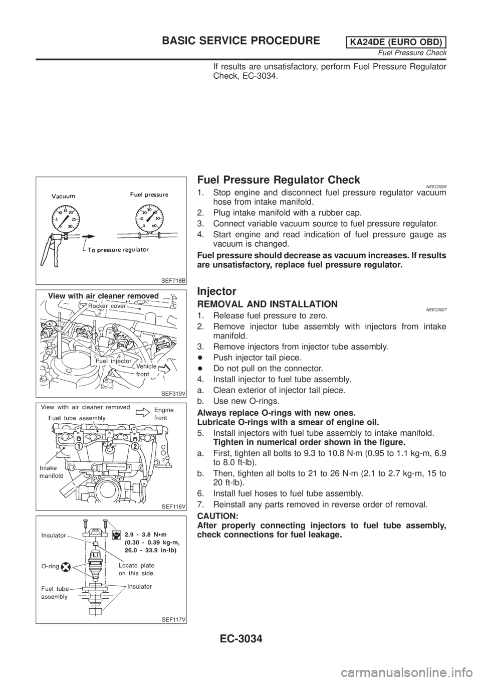
Fuel Pressure Regulator CheckNEEC00261. Stop engine and disconnect fuel pressure regulator vacuum
hose from intake manifold.
2. Plug intake manifold with a rubber cap.
3. Connect variable vacuum source to fuel pressure regulator.
4. Start engine and read indication of fuel pressure gauge as
vacuum is changed.
Fuel pressure should decrease as vacuum increases. If results
are unsatisfactory, replace fuel pressure regulator.
SEF319V
SEF116V
SEF117V
Injector
REMOVAL AND INSTALLATIONNEEC00271. Release fuel pressure to zero.
2. Remove injector tube assembly with injectors from intake
manifold.
3. Remove injectors from injector tube assembly.
+Push injector tail piece.
+Do not pull on the connector.
4. Install injector to fuel tube assembly.
a. Clean exterior of injector tail piece.
b. Use new O-rings.
Always replace O-rings with new ones.
Lubricate O-rings with a smear of engine oil.
5. Install injectors with fuel tube assembly to intake manifold.
Tighten in numerical order shown in the figure.
a. First, tighten all bolts to 9.3 to 10.8 N´m (0.95 to 1.1 kg-m, 6.9
to 8.0 ft-lb).
b. Then, tighten all bolts to 21 to 26 N´m (2.1 to 2.7 kg-m, 15 to
20 ft-lb).
6. Install fuel hoses to fuel tube assembly.
7. Reinstall any parts removed in reverse order of removal.
CAUTION:
After properly connecting injectors to fuel tube assembly,
check connections for fuel leakage.
BASIC SERVICE PROCEDUREKA24DE (EURO OBD)
Fuel Pressure Check
EC-3034
Page 60 of 1306

SEF500V
Fast Idle Cam (FIC)
COMPONENT DESCRIPTIONNEEC0502The FIC is installed on the throttle body to maintain adequate
engine speed while the engine is cold. It is operated by a volumet-
ric change in wax located inside the thermo-element. The thermo-
element is operated by engine coolant temperature.
For inspection refer to ªTROUBLE DIAGNOSIS-BASIC
INSPECTIONº, ªBasic Inspectionº, EC-3086.
Idle Speed/Ignition Timing/Idle Mixture Ratio
Adjustment
NEEC0028PREPARATIONNEEC0028S05+Make sure that the following parts are in good order.
a)Battery
b)Ignition system
c)Engine oil and coolant levels
d)Fuses
e)ECM harness connector
f)Vacuum hoses
g)Air intake system
(Oil filler cap, oil level gauge, etc.)
h)Fuel pressure
i)Engine compression
j)Throttle valve
k)EVAP system
+On models equipped with air conditioner, checks should be carried out while the air conditioner is
ªOFFº.
+When measuring ªCOº percentage, insert probe more than 40 cm (15.7 in) into tail pipe.
+Turn off headlamps, heater blower.
+Keep front wheels pointed straight ahead.
BASIC SERVICE PROCEDUREKA24DE (EURO OBD)
Fast Idle Cam (FIC)
EC-3035
Page 61 of 1306
Overall Inspection SequenceNEEC0028S0501
SEF554YB
NOTE:
If a vehicle contains a part which is operating outside of design specifications with no MI illumination,
the part shall not be replaced prior to emission testing unless it is determined that the part has been
tampered with or abused in such a way that the diagnostic system cannot reasonably be expected to
detect the resulting malfunction.
BASIC SERVICE PROCEDUREKA24DE (EURO OBD)
Idle Speed/Ignition Timing/Idle Mixture Ratio Adjustment
EC-3036