2001 NISSAN PICK-UP service
[x] Cancel search: servicePage 1066 of 1306
TRANSFER
SECTION
TF
MODIFICATION NOTICE:
Transfer components have been changed.
CONTENTS
TRANSFER GEAR CONTROL........................... 3002
MAJOR OVERHAUL........................................... 3003
Case Components ........................................... 3003
Gear Components............................................ 3004
Shift Control Components................................ 3005SERVICE DATA AND SPECIFICATIONS
(SDS).................................................................... 3006
General Specifications ..................................... 3006
Inspection and Adjustment .............................. 3006
TF
Page 1071 of 1306
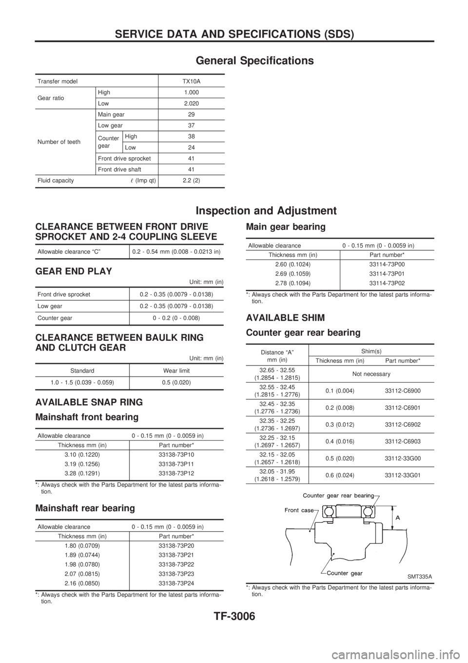
General Specifications
Transfer model TX10A
Gear ratioHigh 1.000
Low 2.020
Number of teethMain gear 29
Low gear 37
Counter
gearHigh 38
Low 24
Front drive sprocket 41
Front drive shaft 41
Fluid capacity!(Imp qt) 2.2 (2)
Inspection and Adjustment
CLEARANCE BETWEEN FRONT DRIVE
SPROCKET AND 2-4 COUPLING SLEEVE
Allowable clearance ªCº 0.2 - 0.54 mm (0.008 - 0.0213 in)
GEAR END PLAY
Unit: mm (in)
Front drive sprocket 0.2 - 0.35 (0.0079 - 0.0138)
Low gear 0.2 - 0.35 (0.0079 - 0.0138)
Counter gear 0 - 0.2 (0 - 0.008)
CLEARANCE BETWEEN BAULK RING
AND CLUTCH GEAR
Unit: mm (in)
Standard Wear limit
1.0 - 1.5 (0.039 - 0.059) 0.5 (0.020)
AVAILABLE SNAP RING
Mainshaft front bearing
Allowable clearance 0 - 0.15 mm (0 - 0.0059 in)
Thickness mm (in) Part number*
3.10 (0.1220) 33138-73P10
3.19 (0.1256) 33138-73P11
3.28 (0.1291) 33138-73P12
*: Always check with the Parts Department for the latest parts informa-
tion.
Mainshaft rear bearing
Allowable clearance 0 - 0.15 mm (0 - 0.0059 in)
Thickness mm (in) Part number*
1.80 (0.0709) 33138-73P20
1.89 (0.0744) 33138-73P21
1.98 (0.0780) 33138-73P22
2.07 (0.0815) 33138-73P23
2.16 (0.0850) 33138-73P24
*: Always check with the Parts Department for the latest parts informa-
tion.
Main gear bearing
Allowable clearance 0 - 0.15 mm (0 - 0.0059 in)
Thickness mm (in) Part number*
2.60 (0.1024) 33114-73P00
2.69 (0.1059) 33114-73P01
2.78 (0.1094) 33114-73P02
*: Always check with the Parts Department for the latest parts informa-
tion.
AVAILABLE SHIM
Counter gear rear bearing
Distance ªAº
mm (in)Shim(s)
Thickness mm (in) Part number*
32.65 - 32.55
(1.2854 - 1.2815)Not necessary
32.55 - 32.45
(1.2815 - 1.2776)0.1 (0.004) 33112-C6900
32.45 - 32.35
(1.2776 - 1.2736)0.2 (0.008) 33112-C6901
32.35 - 32.25
(1.2736 - 1.2697)0.3 (0.012) 33112-C6902
32.25 - 32.15
(1.2697 - 1.2657)0.4 (0.016) 33112-C6903
32.15 - 32.05
(1.2657 - 1.2618)0.5 (0.020) 33112-33G00
32.05 - 31.95
(1.2618 - 1.2579)0.6 (0.024) 33112-33G01
SMT335A
*: Always check with the Parts Department for the latest parts informa-
tion.
SERVICE DATA AND SPECIFICATIONS (SDS)
TF-3006
Page 1072 of 1306
RESTRAINT SYSTEM
SECTION
RS
MODIFICATION NOTICE:
+Diagnosis sensor unit fixing bolt has been changed.
+Front passenger fixing bolt has been changed.
+Driver air bag module has been changed.
+Trouble diagnosis has been changed.
+Deployment procedure of driver air bag module has been changed.
CONTENTS
PRECAUTION...................................................... 3002
Supplemental Restraint System (SRS) ``AIR
BAG'' and ``SEAT BELT PRE-TENSIONER'' .. 3002
SUPPLEMENTAL RESTRAINT SYSTEM
(SRS).................................................................. 3003
Precautions for SRS ``AIR BAG'' and ``SEAT
BELT PRE-TENSIONER'' Service................... 3003
Special Service Tools ...................................... 3003
Commercial Service Tool................................. 3004
Removal and Installation - Diagnosis Sensor
Unit ................................................................... 3005
Removal - Driver Air Bag Module and Spiral
Cable ................................................................ 3006
Installation - Driver Air Bag Module and Spiral
Cable ................................................................ 3007Removal - Front Passenger Air Bag Module .. 3009
Installation - Front Passenger Air Bag
Module ............................................................. 3010
Disposal of Air Bag Module and Seat Belt
Pre-tensioner.................................................... 3011
TROUBLE DIAGNOSES - Supplemental
Restraint System (SRS)..................................... 3014
Trouble Diagnoses Introduction ....................... 3014
How to Perform Trouble Diagnoses for Quick
and Accurate Repair ........................................ 3016
Wiring Diagram - SRS -/LHD........................... 3018
Self-diagnosis................................................... 3020
Trouble Diagnoses for Air Bag Warning
Lamp ................................................................ 3036
COLLISION DIAGNOSIS..................................... 3037
RS
Page 1073 of 1306
Supplemental Restraint System (SRS) ªAIR
BAGº and ªSEAT BELT PRE-TENSIONERº
The Supplemental Restraint System such as ªAIR BAGº and ªSEAT BELT PRE-TENSIONERº used along
with a seat belt, helps to reduce the risk or severity of injury to the driver and front passenger in a frontal
collision. The SRS composition which is available to NISSAN MODEL D22 is as follows (The composition
varies according to the destination and optional equipment.):
Driver air bag module (located in the center of the steering wheel), front passenger air bag module (located
on the instrument panel on passenger side), seat belt pre-tensioner, a diagnosis sensor unit, warning lamp,
wiring harness and spiral cable.
WARNING:
+To avoid rendering the SRS inoperative, which could increase the risk of personal injury or death
in the event of a collision which would result in air bag inflation, all maintenance must be per-
formed by an authorized NISSAN dealer.
+Improper maintenance, including incorrect removal and installation of the SRS, can lead to per-
sonal injury caused by unintentional activation of the system.
+Do not use electrical test equipment on any circuit related to the SRS unless instructed to in this
Service Manual. SRS wiring harnesses can be identified by yellow harness connector.
PRECAUTION
RS-3002
Page 1074 of 1306
Precautions for SRS ªAIR BAGº and ªSEAT
BELT PRE-TENSIONERº Service
+Do not use electrical test equipment to check SRS circuits unless instructed to in this Service Manual.
+Before servicing the SRS, turn ignition switch ªOFFº, disconnect battery ground cable and wait at least 3
minutes.
For approximately 3 minutes after the cables are removed, it is still possible for the air bag and seat belt
pre-tensioner to deploy. Therefore, do not work on any SRS connectors or wires until at least 3 minutes have
passed.
+Diagnosis sensor unit must always be installed with their arrow marks ª
Sº pointing towards the front of
the vehicle for proper operation. Also check diagnosis sensor unit for cracks, deformities or rust before
installation and replace as required.
+The spiral cable must be aligned with the neutral position since its rotations are limited. Do not attempt
to turn steering wheel or column after removal of steering gear.
+Handle air bag module carefully. Always place driver and passenger air bag modules with the pad side
facing upward.
+Conduct self-diagnosis to check entire SRS for proper function after replacing any components.
+After air bag inflates, the front instrument panel assembly should be replaced if damaged.
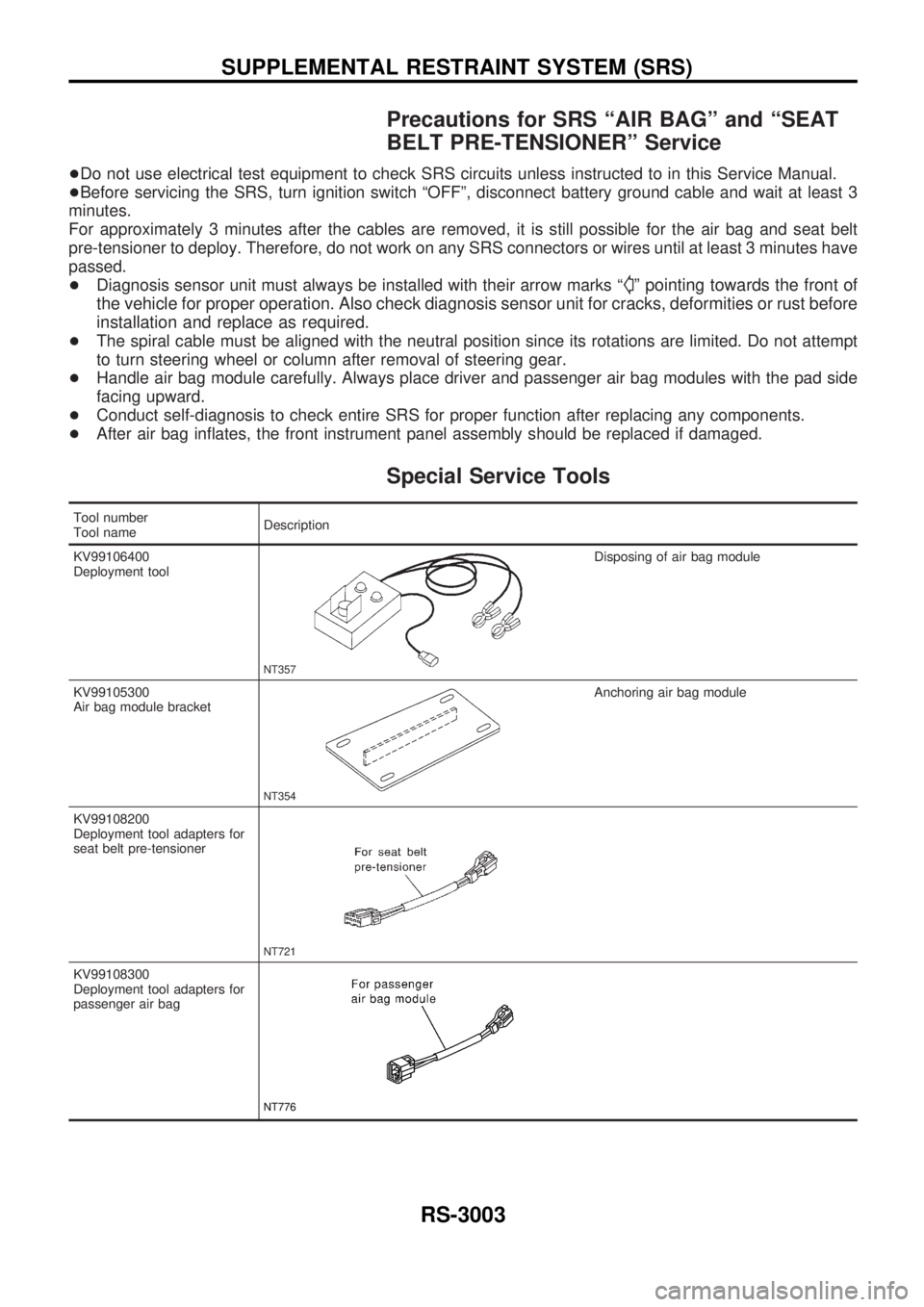
Special Service Tools
Tool number
Tool nameDescription
KV99106400
Deployment tool
NT357
Disposing of air bag module
KV99105300
Air bag module bracket
NT354
Anchoring air bag module
KV99108200
Deployment tool adapters for
seat belt pre-tensioner
NT721
KV99108300
Deployment tool adapters for
passenger air bag
NT776
SUPPLEMENTAL RESTRAINT SYSTEM (SRS)
RS-3003
Page 1075 of 1306

Tool number
Tool nameDescription
KV99109700
Deployment tool adapter for
driver air bag
JRS995
Commercial Service Tool
Tool name Description Specification
Tamper resistant torx
socket
NT757
Size: T30
SUPPLEMENTAL RESTRAINT SYSTEM (SRS)
Special Service Tools (Cont'd)
RS-3004
Page 1076 of 1306
Removal and Installation Ð Diagnosis
Sensor Unit
CAUTION:
+Before servicing SRS, turn the ignition switch off, disconnect battery ground cable and wait at
least 3 minutes.
+Do not use old bolts and nuts after removal; replace with new ones.
+Check diagnosis sensor unit for proper installation.
+Check diagnosis sensor unit to ensure it is free of deformities, dents, cracks or rust. If it shows
any visible signs of damage, replace it with a new one.
+Check diagnosis sensor unit brackets to ensure they are free of deformities and rust.
+After replacement of diagnosis sensor unit, check SRS function and perform self-diagnosis for
SRS. Refer to ªSelf-diagnosisº for details. (RS-3020)
+Do not attempt to disassemble diagnosis sensor unit.
+Replace diagnosis sensor unit if it has been dropped or sustained an impact.
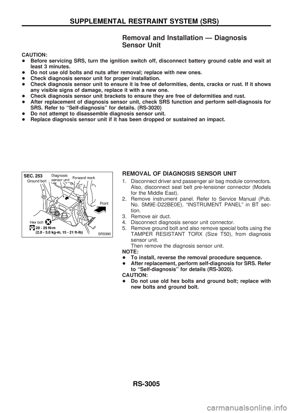
REMOVAL OF DIAGNOSIS SENSOR UNIT
1. Disconnect driver and passenger air bag module connectors.
Also, disconnect seat belt pre-tensioner connector (Models
for the Middle East).
2. Remove instrument panel. Refer to Service Manual (Pub.
No. SM9E-D22BE0E), ªINSTRUMENT PANELº in BT sec-
tion.
3. Remove air duct.
4. Disconnect diagnosis sensor unit connector.
5. Remove ground bolt and also remove special bolts using the
TAMPER RESISTANT TORX (Size T50), from diagnosis
sensor unit.
Then remove the diagnosis sensor unit.
NOTE:
+To install, reverse the removal procedure sequence.
+After replacement, perform self-diagnosis for SRS. Refer
to ªSelf-diagnosisº for details (RS-3020).
CAUTION:
+Do not use old hex bolts and ground bolt; replace with
new bolts and ground bolt.
SRS990
SUPPLEMENTAL RESTRAINT SYSTEM (SRS)
RS-3005
Page 1079 of 1306
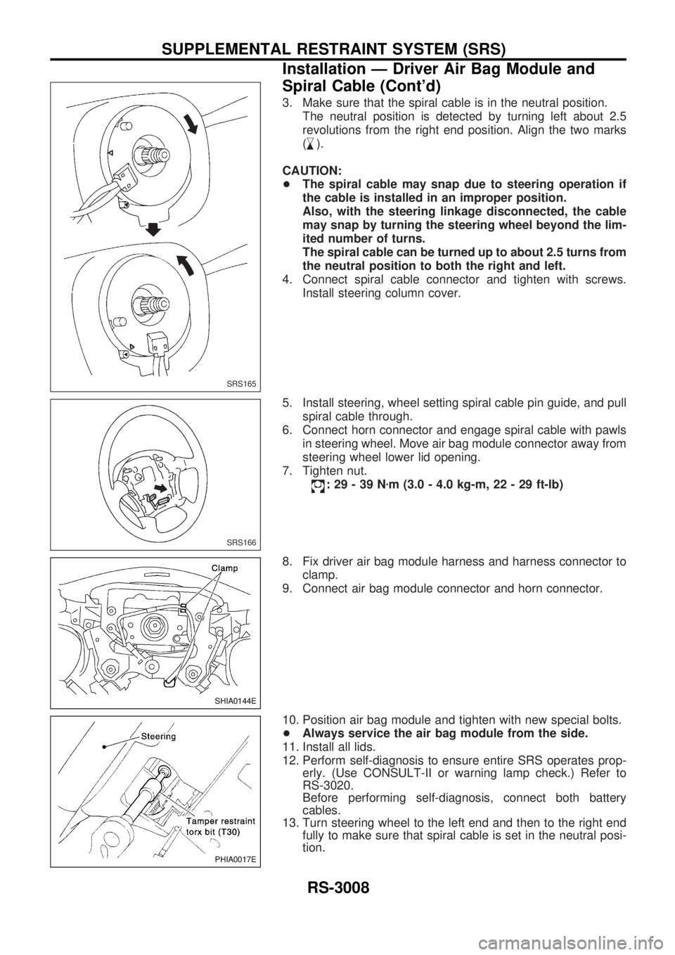
3. Make sure that the spiral cable is in the neutral position.
The neutral position is detected by turning left about 2.5
revolutions from the right end position. Align the two marks
(
,
m).
CAUTION:
+The spiral cable may snap due to steering operation if
the cable is installed in an improper position.
Also, with the steering linkage disconnected, the cable
may snap by turning the steering wheel beyond the lim-
ited number of turns.
The spiral cable can be turned up to about 2.5 turns from
the neutral position to both the right and left.
4. Connect spiral cable connector and tighten with screws.
Install steering column cover.
5. Install steering, wheel setting spiral cable pin guide, and pull
spiral cable through.
6. Connect horn connector and engage spiral cable with pawls
in steering wheel. Move air bag module connector away from
steering wheel lower lid opening.
7. Tighten nut.
:29-39Nzm (3.0 - 4.0 kg-m, 22 - 29 ft-lb)
8. Fix driver air bag module harness and harness connector to
clamp.
9. Connect air bag module connector and horn connector.
10. Position air bag module and tighten with new special bolts.
+Always service the air bag module from the side.
11. Install all lids.
12. Perform self-diagnosis to ensure entire SRS operates prop-
erly. (Use CONSULT-II or warning lamp check.) Refer to
RS-3020.
Before performing self-diagnosis, connect both battery
cables.
13. Turn steering wheel to the left end and then to the right end
fully to make sure that spiral cable is set in the neutral posi-
tion.
SRS165
SRS166
SHIA0144E
PHIA0017E
SUPPLEMENTAL RESTRAINT SYSTEM (SRS)
Installation Ð Driver Air Bag Module and
Spiral Cable (Cont'd)
RS-3008