2001 NISSAN PICK-UP reset
[x] Cancel search: resetPage 49 of 1306

Multiport Fuel Injection (MFI) System
DESCRIPTIONNEEC0014Input/Output Signal ChartNEEC0014S01
Sensor Input Signal to ECMECM func-
tionActuator
Camshaft position sensor Engine speed and piston position
Fuel injec-
tion & mix-
ture ratio
controlInjector Mass air flow sensor Amount of intake air
Engine coolant temperature sensor Engine coolant temperature
Heated oxygen sensor 1 Density of oxygen in exhaust gas
Throttle position sensorThrottle position
Throttle valve idle position
PNP switch Gear position
Vehicle speed sensor Vehicle speed
Ignition switch Start signal
Air conditioner switch Air conditioner operation
Knock sensor Engine knocking condition
Battery Battery voltage
Power steering oil pressure switch Power steering operation
Heated oxygen sensor 2* Density of oxygen in exhaust gas
* Under normal conditions, this sensor is not for engine control operation.
Basic Multiport Fuel Injection SystemNEEC0014S02The amount of fuel injected from the fuel injector is determined by the ECM. The ECM controls the length of
time the valve remains open (injection pulse duration). The amount of fuel injected is a program value in the
ECM memory. The program value is preset by engine operating conditions. These conditions are determined
by input signals (for engine speed and intake air) from both the camshaft position sensor and the mass air
flow sensor.
Various Fuel Injection Increase/Decrease CompensationNEEC0014S03In addition, the amount of fuel injected is compensated to improve engine performance under various oper-
ating conditions as listed below.
+During warm-up
+When starting the engine
+During acceleration
+Hot-engine operation
+High-load, high-speed operation
+During deceleration
+During high engine speed operation
ENGINE AND EMISSION BASIC CONTROL SYSTEM
DESCRIPTION
KA24DE (EURO OBD)
Multiport Fuel Injection (MFI) System
EC-3024
Page 90 of 1306
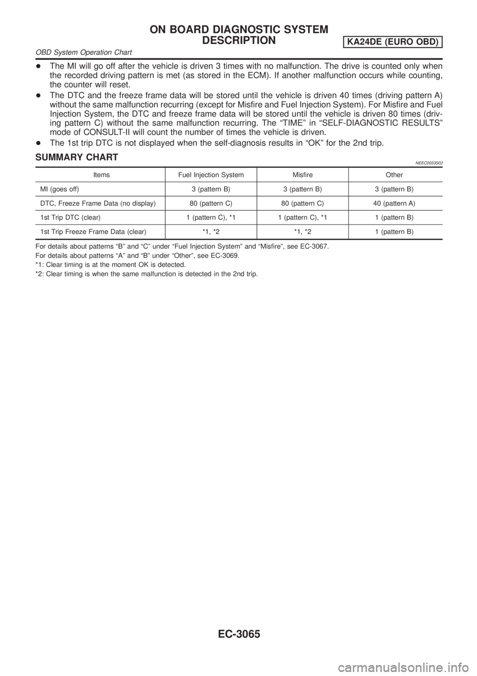
+The MI will go off after the vehicle is driven 3 times with no malfunction. The drive is counted only when
the recorded driving pattern is met (as stored in the ECM). If another malfunction occurs while counting,
the counter will reset.
+The DTC and the freeze frame data will be stored until the vehicle is driven 40 times (driving pattern A)
without the same malfunction recurring (except for Misfire and Fuel Injection System). For Misfire and Fuel
Injection System, the DTC and freeze frame data will be stored until the vehicle is driven 80 times (driv-
ing pattern C) without the same malfunction recurring. The ªTIMEº in ªSELF-DIAGNOSTIC RESULTSº
mode of CONSULT-II will count the number of times the vehicle is driven.
+The 1st trip DTC is not displayed when the self-diagnosis results in ªOKº for the 2nd trip.
SUMMARY CHARTNEEC0033S02
Items Fuel Injection System Misfire Other
MI (goes off) 3 (pattern B) 3 (pattern B) 3 (pattern B)
DTC, Freeze Frame Data (no display) 80 (pattern C) 80 (pattern C) 40 (pattern A)
1st Trip DTC (clear) 1 (pattern C), *1 1 (pattern C), *1 1 (pattern B)
1st Trip Freeze Frame Data (clear) *1, *2 *1, *2 1 (pattern B)
For details about patterns ªBº and ªCº under ªFuel Injection Systemº and ªMisfireº, see EC-3067.
For details about patterns ªAº and ªBº under ªOtherº, see EC-3069.
*1: Clear timing is at the moment OK is detected.
*2: Clear timing is when the same malfunction is detected in the 2nd trip.
ON BOARD DIAGNOSTIC SYSTEM
DESCRIPTION
KA24DE (EURO OBD)
OBD System Operation Chart
EC-3065
Page 104 of 1306
When you are inspecting the circuit by gently shaking (or twist-
ing) the suspicious connectors, components and harness in
the ªDIAGNOSTIC TROUBLE CODE CONFIRMATION
PROCEDUREº, the moment a malfunction is found the DTC/
1st trip DTC will be displayed. (Refer to ªIncident Simulation
Testsº in ªHOW TO PERFORM EFFICIENT DIAGNOSIS FOR
AN ELECTRICAL INCIDENTº, GI section.
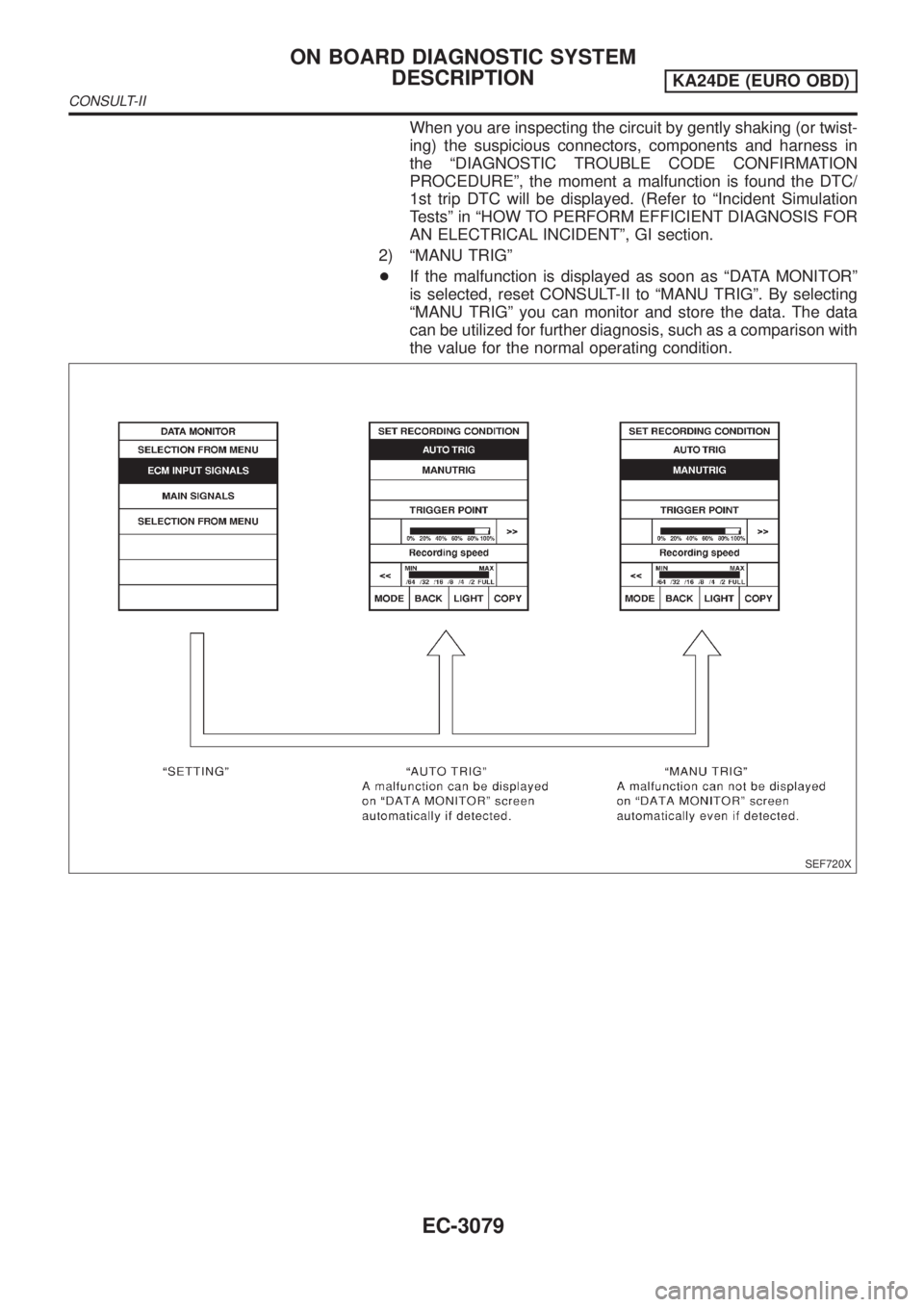
2) ªMANU TRIGº
+If the malfunction is displayed as soon as ªDATA MONITORº
is selected, reset CONSULT-II to ªMANU TRIGº. By selecting
ªMANU TRIGº you can monitor and store the data. The data
can be utilized for further diagnosis, such as a comparison with
the value for the normal operating condition.
SEF720X
ON BOARD DIAGNOSTIC SYSTEM
DESCRIPTION
KA24DE (EURO OBD)
CONSULT-II
EC-3079
Page 106 of 1306
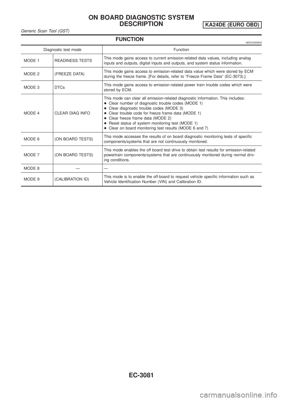
FUNCTIONNEEC0035S03
Diagnostic test mode Function
MODE 1 READINESS TESTSThis mode gains access to current emission-related data values, including analog
inputs and outputs, digital inputs and outputs, and system status information.
MODE 2 (FREEZE DATA)This mode gains access to emission-related data value which were stored by ECM
during the freeze frame. [For details, refer to ªFreeze Frame Dataº (EC-3073).]
MODE 3 DTCsThis mode gains access to emission-related power train trouble codes which were
stored by ECM.
MODE 4 CLEAR DIAG INFOThis mode can clear all emission-related diagnostic information. This includes:
+Clear number of diagnostic trouble codes (MODE 1)
+Clear diagnostic trouble codes (MODE 3)
+Clear trouble code for freeze frame data (MODE 1)
+Clear freeze frame data (MODE 2)
+Reset status of system monitoring test (MODE 1)
+Clear on board monitoring test results (MODE 6 and 7)
MODE 6 (ON BOARD TESTS)This mode accesses the results of on board diagnostic monitoring tests of specific
components/systems that are not continuously monitored.
MODE 7 (ON BOARD TESTS)This mode enables the off board test drive to obtain test results for emission-related
powertrain components/systems that are continuously monitored during normal driv-
ing conditions.
MODE 8 Ð Ð
MODE 9 (CALIBRATION ID)This mode is to enable the off-board to request vehicle specific information such as
Vehicle Identification Number (VIN) and Calibration ID.
ON BOARD DIAGNOSTIC SYSTEM
DESCRIPTION
KA24DE (EURO OBD)
Generic Scan Tool (GST)
EC-3081
Page 119 of 1306
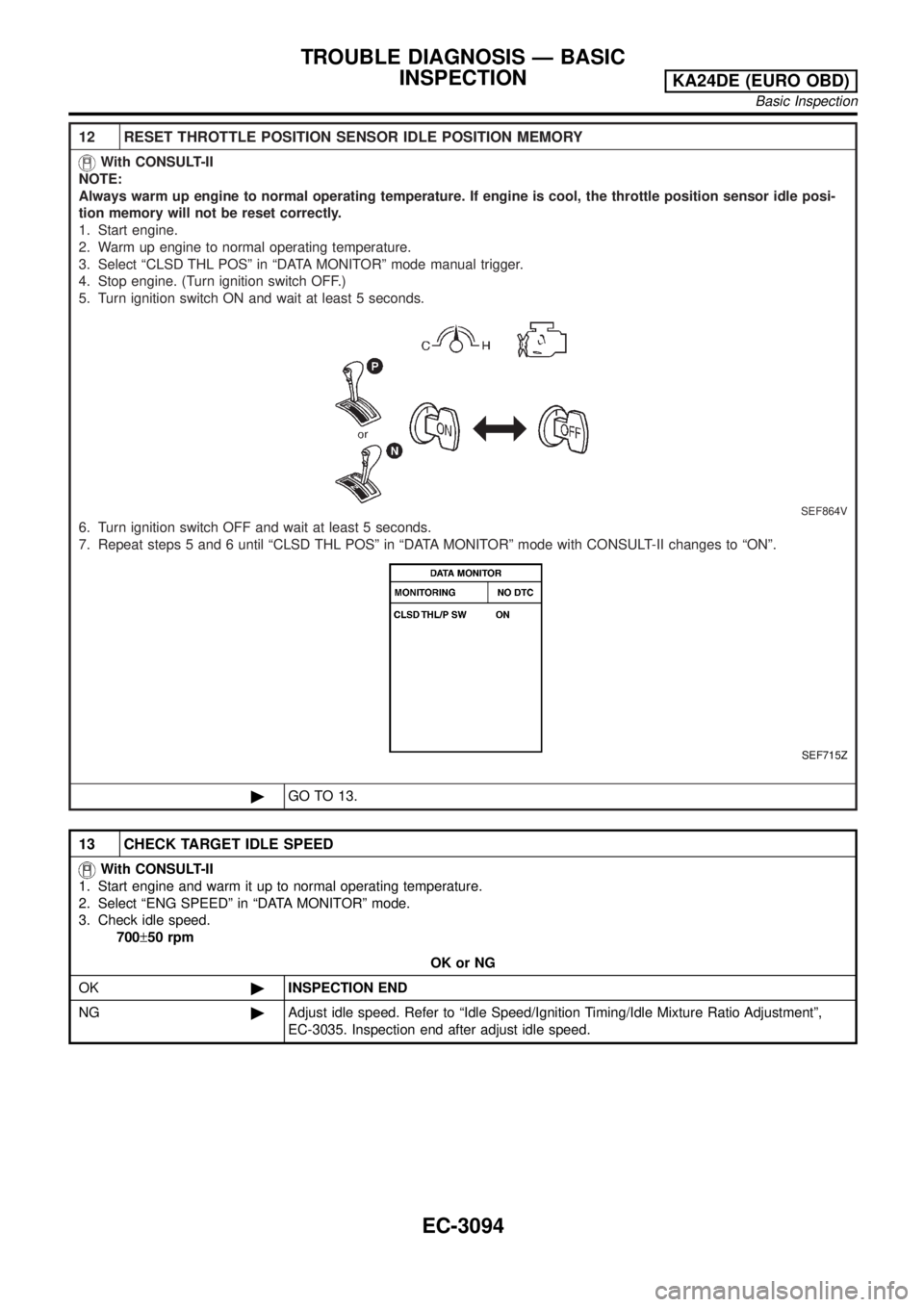
12 RESET THROTTLE POSITION SENSOR IDLE POSITION MEMORY
With CONSULT-II
NOTE:
Always warm up engine to normal operating temperature. If engine is cool, the throttle position sensor idle posi-
tion memory will not be reset correctly.
1. Start engine.
2. Warm up engine to normal operating temperature.
3. Select ªCLSD THL POSº in ªDATA MONITORº mode manual trigger.
4. Stop engine. (Turn ignition switch OFF.)
5. Turn ignition switch ON and wait at least 5 seconds.
SEF864V
6. Turn ignition switch OFF and wait at least 5 seconds.
7. Repeat steps 5 and 6 until ªCLSD THL POSº in ªDATA MONITORº mode with CONSULT-II changes to ªONº.
SEF715Z
©GO TO 13.
13 CHECK TARGET IDLE SPEED
With CONSULT-II
1. Start engine and warm it up to normal operating temperature.
2. Select ªENG SPEEDº in ªDATA MONITORº mode.
3. Check idle speed.
700±50 rpm
OK or NG
OK©INSPECTION END
NG©Adjust idle speed. Refer to ªIdle Speed/Ignition Timing/Idle Mixture Ratio Adjustmentº,
EC-3035. Inspection end after adjust idle speed.
TROUBLE DIAGNOSIS Ð BASIC
INSPECTION
KA24DE (EURO OBD)
Basic Inspection
EC-3094
Page 124 of 1306
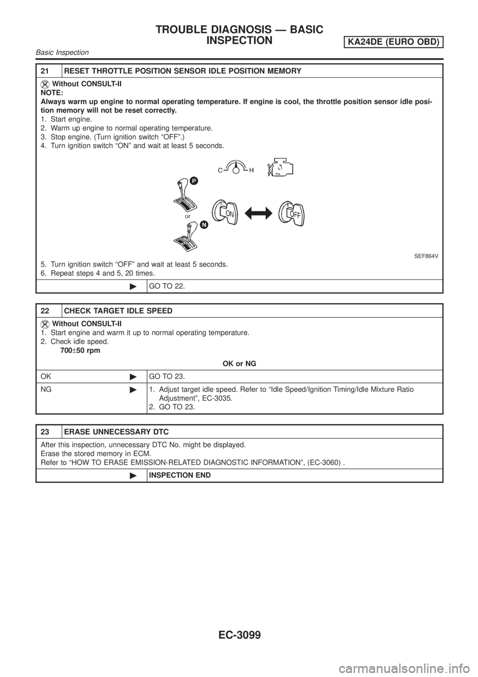
21 RESET THROTTLE POSITION SENSOR IDLE POSITION MEMORY
Without CONSULT-II
NOTE:
Always warm up engine to normal operating temperature. If engine is cool, the throttle position sensor idle posi-
tion memory will not be reset correctly.
1. Start engine.
2. Warm up engine to normal operating temperature.
3. Stop engine. (Turn ignition switch ªOFFº.)
4. Turn ignition switch ªONº and wait at least 5 seconds.
SEF864V
5. Turn ignition switch ªOFFº and wait at least 5 seconds.
6. Repeat steps 4 and 5, 20 times.
©GO TO 22.
22 CHECK TARGET IDLE SPEED
Without CONSULT-II
1. Start engine and warm it up to normal operating temperature.
2. Check idle speed.
700±50 rpm
OK or NG
OK©GO TO 23.
NG©1. Adjust target idle speed. Refer to ªIdle Speed/Ignition Timing/Idle Mixture Ratio
Adjustmentº, EC-3035.
2. GO TO 23.
23 ERASE UNNECESSARY DTC
After this inspection, unnecessary DTC No. might be displayed.
Erase the stored memory in ECM.
Refer to ªHOW TO ERASE EMISSION-RELATED DIAGNOSTIC INFORMATIONº, (EC-3060) .
©INSPECTION END
TROUBLE DIAGNOSIS Ð BASIC
INSPECTION
KA24DE (EURO OBD)
Basic Inspection
EC-3099
Page 126 of 1306
Fail-safe Chart=NEEC0040The ECM enters fail-safe mode if any of the following malfunctions is detected due to the open or short cir-
cuit. When the ECM enters the fail-safe mode, the MI illuminates.
DTC No.
Detected items Engine operating condition in fail-safe mode
CONSULT-II
GST
P0102
P0103Mass air flow sensor cir-
cuitEngine speed will not rise more than 2,400 rpm due to the fuel cut.
P0112
P0113Intake air temperature sen-
sorThe ECM functions on the assumption that the intake air temperature is 25ÉC (77ÉF).
P0117
P0118Engine coolant tempera-
ture sensor circuitEngine coolant temperature will be determined by ECM based on the time after turn-
ing ignition switch to ON or START.
CONSULT-II displays the engine coolant temperature decided by ECM.
ConditionEngine coolant temperature decided (CONSULT-
II display)
Just as ignition switch is turned to
ON or Start40ÉC (104ÉF)
More than approx. 4 minutes after
ignition ON or Start80ÉC (176ÉF)
Except as shown above40 - 80ÉC (104 - 176ÉF)
(Depends on the time)
P0122
P0123Throttle position sensor
circuitThrottle position will be determined based on the injected fuel amount and the engine
speed. Therefore, acceleration will be poor.
Condition Driving condition
When engine is idling Normal
When accelerating Poor acceleration
Unable to
access ECMECMECM fail-safe activating condition
The computing function of the ECM was judged to be malfunctioning.
When the fail-safe system activates (i.e., if the ECM detects a malfunction condition in
the CPU of ECM), the MI on the instrument panel lights to warn the driver.
However it is not possible to access ECM and DTC cannot be confirmed.
Engine control with fail-safe
When ECM fail-safe is operating, fuel injection, ignition timing, fuel pump operation
and IACV-AAC valve operation are controlled under certain limitations.
ECM fail-safe operation
Engine speedEngine speed will not rise more than 3,000
rpm
Fuel injection Simultaneous multiport fuel injection system
Ignition timing Ignition timing is fixed at the preset valve
Fuel pumpFuel pump relay is ªONº when engine is running
and ªOFFº when engine stalls
IACV-AAC valve Full open
Replace ECM, if ECM fail-safe condition is confirmed.
TROUBLE DIAGNOSIS Ð GENERAL
DESCRIPTION
KA24DE (EURO OBD)
Fail-safe Chart
EC-3101
Page 436 of 1306
Fuel Injection Control System
DESCRIPTION
System description
Three types of fuel injection control are provided to accommodate engine operating conditions; normal
control, idle control and start control. The ECM determines the appropriate fuel injection control. Under each
control, the amount of fuel injected is compensated to improve engine performance.
Pulse signals are exchanged between ECM and electronic control fuel injection pump (control unit is built-
in). The fuel injection pump control unit performs duty control on the spill valve (built into the fuel injection
pump) according to the input signals to compensate the amount of fuel injected to the preset value.
Start control
Input/output signal chart
Sensor Input Signal to ECM ECM Function Actuator
Engine coolant temperature sensor Engine coolant temperature
Fuel injection con-
trol (start control)Electronic control fuel injec-
tion pump Crankshaft position sensor (TDC) Engine speed
Ignition switch Start signal
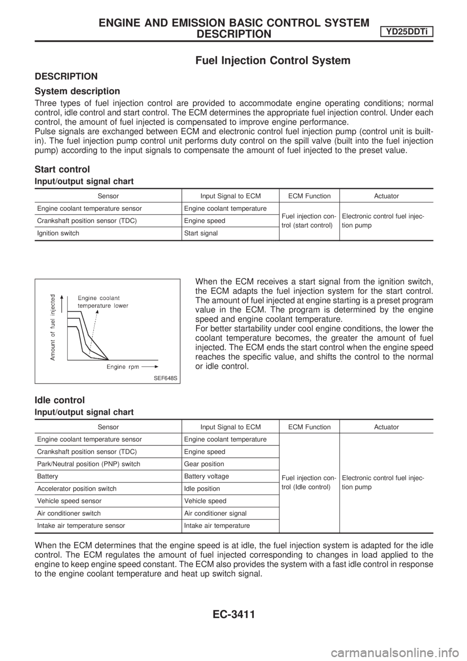
When the ECM receives a start signal from the ignition switch,
the ECM adapts the fuel injection system for the start control.
The amount of fuel injected at engine starting is a preset program
value in the ECM. The program is determined by the engine
speed and engine coolant temperature.
For better startability under cool engine conditions, the lower the
coolant temperature becomes, the greater the amount of fuel
injected. The ECM ends the start control when the engine speed
reaches the specific value, and shifts the control to the normal
or idle control.
Idle control
Input/output signal chart
Sensor Input Signal to ECM ECM Function Actuator
Engine coolant temperature sensor Engine coolant temperature
Fuel injection con-
trol (Idle control)Electronic control fuel injec-
tion pump Crankshaft position sensor (TDC) Engine speed
Park/Neutral position (PNP) switch Gear position
Battery Battery voltage
Accelerator position switch Idle position
Vehicle speed sensor Vehicle speed
Air conditioner switch Air conditioner signal
Intake air temperature sensor Intake air temperature
When the ECM determines that the engine speed is at idle, the fuel injection system is adapted for the idle
control. The ECM regulates the amount of fuel injected corresponding to changes in load applied to the
engine to keep engine speed constant. The ECM also provides the system with a fast idle control in response
to the engine coolant temperature and heat up switch signal.
SEF648S
ENGINE AND EMISSION BASIC CONTROL SYSTEM
DESCRIPTIONYD25DDTi
EC-3411