2001 NISSAN PICK-UP reset
[x] Cancel search: resetPage 463 of 1306
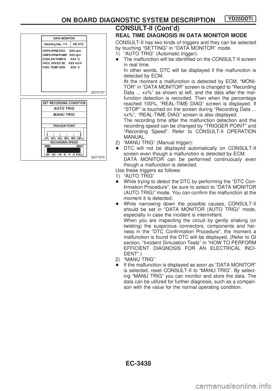
REAL TIME DIAGNOSIS IN DATA MONITOR MODE
CONSULT-II has two kinds of triggers and they can be selected
by touching ªSETTINGº in ªDATA MONITORº mode.
1) ªAUTO TRIGº (Automatic trigger):
+The malfunction will be identified on the CONSULT-II screen
in real time.
In other words, DTC will be displayed if the malfunction is
detected by ECM.
At the moment a malfunction is detected by ECM, ªMONI-
TORº in ªDATA MONITORº screen is changed to ªRecording
Data ... xx%º as shown at left, and the data after the mal-
function detection is recorded. Then when the percentage
reached 100%, ªREAL-TIME DIAGº screen is displayed. If
ªSTOPº is touched on the screen during ªRecording Data ...
xx%º, ªREAL-TIME DIAGº screen is also displayed.
The recording time after the malfunction detection and the
recording speed can be changed by ªTRIGGER POINTº and
ªRecording Speedº. Refer to CONSULT-II OPERATION
MANUAL.
2) ªMANU TRIGº (Manual trigger):
+DTC will not be displayed automatically on CONSULT-II
screen even though a malfunction is detected by ECM.
DATA MONITOR can be performed continuously even
though a malfunction is detected.
Use these triggers as follows:
1) ªAUTO TRIGº
+While trying to detect the DTC by performing the ªDTC Con-
firmation Procedureº, be sure to select to ªDATA MONITOR
(AUTO TRIG)º mode. You can confirm the malfunction at the
moment it is detected.
+While narrowing down the possible causes, CONSULT-II
should be set in ªDATA MONITOR (AUTO TRIG)º mode,
especially in case the incident is intermittent.
When you are inspecting the circuit by gently shaking (or
twisting) the suspicious connectors, components and har-
ness in the ªDTC Confirmation Procedureº, the moment a
malfunction is found the DTC will be displayed. (Refer to GI
section, ªIncident Simulation Testsº in ªHOW TO PERFORM
EFFICIENT DIAGNOSIS FOR AN ELECTRICAL INCI-
DENTº.)
2) ªMANU TRIGº
+If the malfunction is displayed as soon as ªDATA MONITORº
is selected, reset CONSULT-II to ªMANU TRIGº. By select-
ing ªMANU TRIGº you can monitor and store the data. The
data can be utilized for further diagnosis, such as a compari-
son with the value for the normal operating condition.
SEF373Y
SEF707X
ON BOARD DIAGNOSTIC SYSTEM DESCRIPTIONYD25DDTi
CONSULT-II (Cont'd)
EC-3438
Page 552 of 1306
11 CHECK ACCELERATOR POSITION SENSOR SHIELD CIRCUIT FOR OPEN AND SHORT
1. Turn ignition switch ªOFFº.
2. Check harness continuity between harness connector F55 terminal 13 and engine ground. Refer to Wiring Diagram.
Continuity should exist.
3. Also check harness for short to power.
OK or NG
OK (With CONSULT-II)cGO TO 13.
OK (Without CONSULT-II)cGO TO 14.
NGcGO TO 12.
12 DETECT MALFUNCTIONING PART
Check the following.
+Harness connectors M47, F55
+Harness for open or short between harness connector F55 and engine ground
cRepair harness or connectors.
13 RESET ACCELERATOR POSITION SENSOR IDLE POSITION MEMORY
With CONSULT-II
1. Turn ignition switch ªONº.
2. Select ªOFF ACCEL PO SIGº in ªACTIVE TESTº mode with CONSULT-II.
3. Touch ªCLEARº.
cGO TO 24.
14 RESET ACCELERATOR POSITION SENSOR IDLE POSITION MEMORY
Without CONSULT-II
1. Start engine and warm it up to normal operating temperature.
2. Let engine idle for 10 minutes.
cGO TO 24.
DTC 0403 ACCEL POS SENSORYD25DDTi
Diagnostic Procedure (Cont'd)
EC-3527
Page 555 of 1306
22 RESET ACCELERATOR POSITION SENSOR IDLE POSITION MEMORY
With CONSULT-II
1. Reconnect all connectors disconnected.
2. Turn ignition switch ªONº.
3. Select ªOFF ACCEL PO SIGº in ªACTIVE TESTº mode with CONSULT-II.
4. Touch ªCLEARº.
cGO TO 24.
23 RESET ACCELERATOR POSITION SENSOR IDLE POSITION MEMORY
Without CONSULT-II
1. Reconnect all connectors disconnected.
2. Start engine and warm it up to normal operating temperature.
3. Let engine idle for 10 minutes.
cGO TO 24.
24 CHECK INTERMITTENT INCIDENT
Refer to ªTROUBLE DIAGNOSIS FOR INTERMITTENT INCIDENTº, EC-3469.
cINSPECTION END
DTC 0403 ACCEL POS SENSORYD25DDTi
Diagnostic Procedure (Cont'd)
EC-3530
Page 807 of 1306
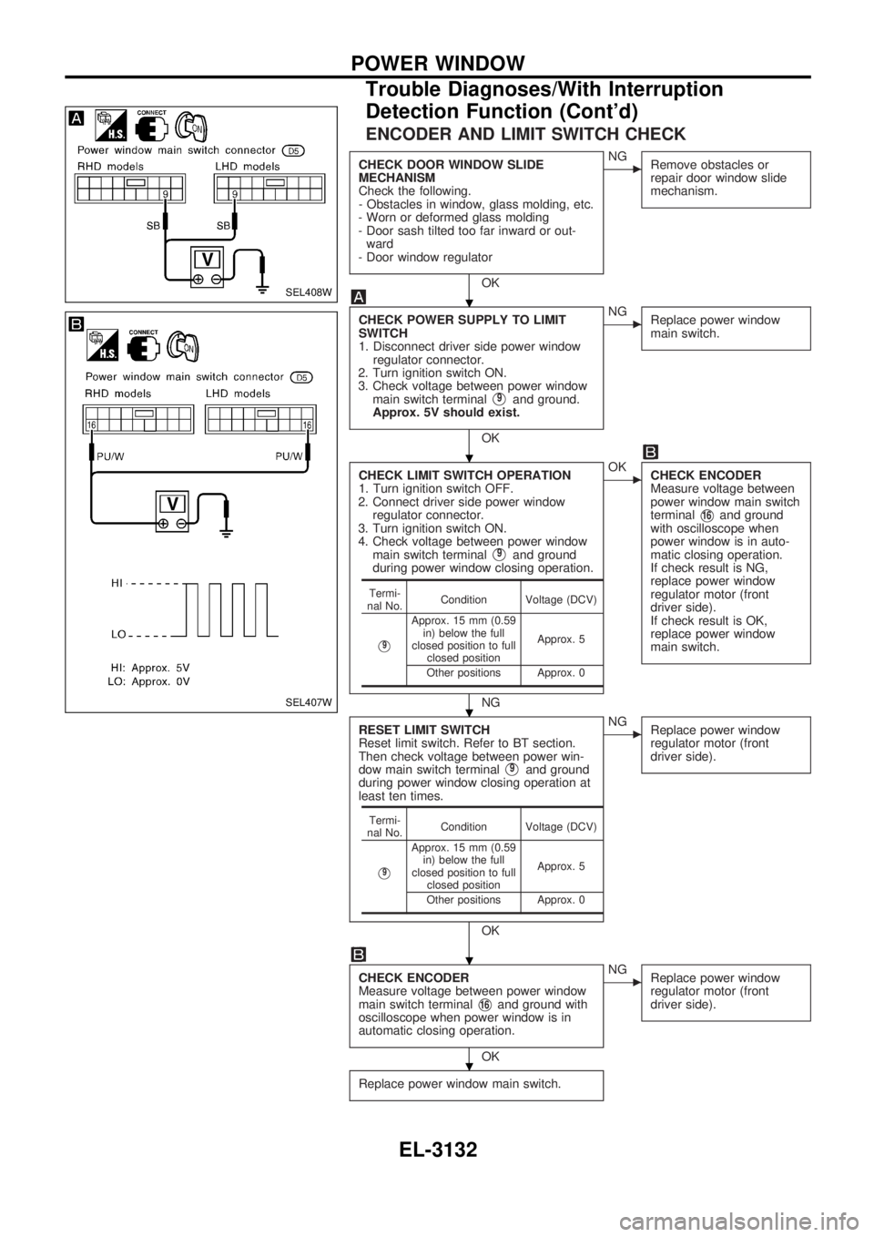
ENCODER AND LIMIT SWITCH CHECK
CHECK DOOR WINDOW SLIDE
MECHANISM
Check the following.
- Obstacles in window, glass molding, etc.
- Worn or deformed glass molding
- Door sash tilted too far inward or out-
ward
- Door window regulator
OK
cNG
Remove obstacles or
repair door window slide
mechanism.
CHECK POWER SUPPLY TO LIMIT
SWITCH
1. Disconnect driver side power window
regulator connector.
2. Turn ignition switch ON.
3. Check voltage between power window
main switch terminal
V9and ground.
Approx. 5V should exist.
OK
cNG
Replace power window
main switch.
CHECK LIMIT SWITCH OPERATION
1. Turn ignition switch OFF.
2. Connect driver side power window
regulator connector.
3. Turn ignition switch ON.
4. Check voltage between power window
main switch terminal
V9and ground
during power window closing operation.
NG
cOK
CHECK ENCODER
Measure voltage between
power window main switch
terminal
V16and ground
with oscilloscope when
power window is in auto-
matic closing operation.
If check result is NG,
replace power window
regulator motor (front
driver side).
If check result is OK,
replace power window
main switch.
RESET LIMIT SWITCH
Reset limit switch. Refer to BT section.
Then check voltage between power win-
dow main switch terminal
V9and ground
during power window closing operation at
least ten times.
OK
cNG
Replace power window
regulator motor (front
driver side).
CHECK ENCODER
Measure voltage between power window
main switch terminal
V16and ground with
oscilloscope when power window is in
automatic closing operation.
OK
cNG
Replace power window
regulator motor (front
driver side).
Replace power window main switch.
Termi-
nal No.Condition Voltage (DCV)
V9
Approx. 15 mm (0.59
in) below the full
closed position to full
closed positionApprox. 5
Other positions Approx. 0
Termi-
nal No.Condition Voltage (DCV)
V9
Approx. 15 mm (0.59
in) below the full
closed position to full
closed positionApprox. 5
Other positions Approx. 0
SEL408W
SEL407W
.
.
.
.
.
POWER WINDOW
Trouble Diagnoses/With Interruption
Detection Function (Cont'd)
EL-3132
Page 1085 of 1306
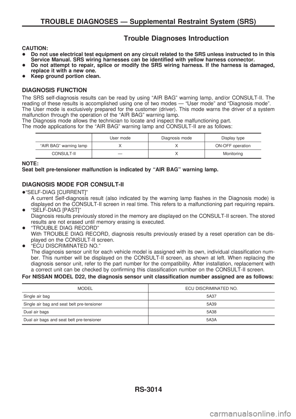
Trouble Diagnoses Introduction
CAUTION:
+Do not use electrical test equipment on any circuit related to the SRS unless instructed to in this
Service Manual. SRS wiring harnesses can be identified with yellow harness connector.
+Do not attempt to repair, splice or modify the SRS wiring harness. If the harness is damaged,
replace it with a new one.
+Keep ground portion clean.
DIAGNOSIS FUNCTION
The SRS self-diagnosis results can be read by using ªAIR BAGº warning lamp, and/or CONSULT-II. The
reading of these results is accomplished using one of two modes Ð ªUser modeº and ªDiagnosis modeº.
The User mode is exclusively prepared for the customer (driver). This mode warns the driver of a system
malfunction through the operation of the ªAIR BAGº warning lamp.
The Diagnosis mode allows the technician to locate and inspect the malfunctioning part.
The mode applications for the ªAIR BAGº warning lamp and CONSULT-II are as follows:
User mode Diagnosis mode Display type
ªAIR BAGº warning lamp X X ON-OFF operation
CONSULT-II Ð X Monitoring
NOTE:
Seat belt pre-tensioner malfunction is indicated by ªAIR BAGº warning lamp.
DIAGNOSIS MODE FOR CONSULT-II
+ªSELF-DIAG [CURRENT]º
A current Self-diagnosis result (also indicated by the warning lamp flashes in the Diagnosis mode) is
displayed on the CONSULT-II screen in real time. This refers to a malfunctioning part requiring repairs.
+ªSELF-DIAG [PAST]º
Diagnosis results previously stored in the memory are displayed on the CONSULT-II screen. The stored
results are not erased until memory erasing is executed.
+ªTROUBLE DIAG RECORDº
With TROUBLE DIAG RECORD, diagnosis results previously erased by a reset operation can be dis-
played on the CONSULT-II screen.
+ªECU DISCRIMINATED NO.º
The diagnosis sensor unit for each vehicle model is assigned with its own, individual classification num-
ber. This number will be displayed on the CONSULT-II screen, as shown at left. When replacing the
diagnosis sensor unit, refer to the part number for the compatibility. After installation, replacement with
a correct unit can be checked by confirming this classification number on the CONSULT-II screen.
For NISSAN MODEL D22, the diagnosis sensor unit classification number assigned are as follows:
MODEL ECU DISCRIMINATED NO.
Single air bag5A37
Single air bag and seat belt pre-tensioner 5A39
Dual air bags5A38
Dual air bags and seat belt pre-tensioner 5A3A
TROUBLE DIAGNOSES Ð Supplemental Restraint System (SRS)
RS-3014
Page 1101 of 1306
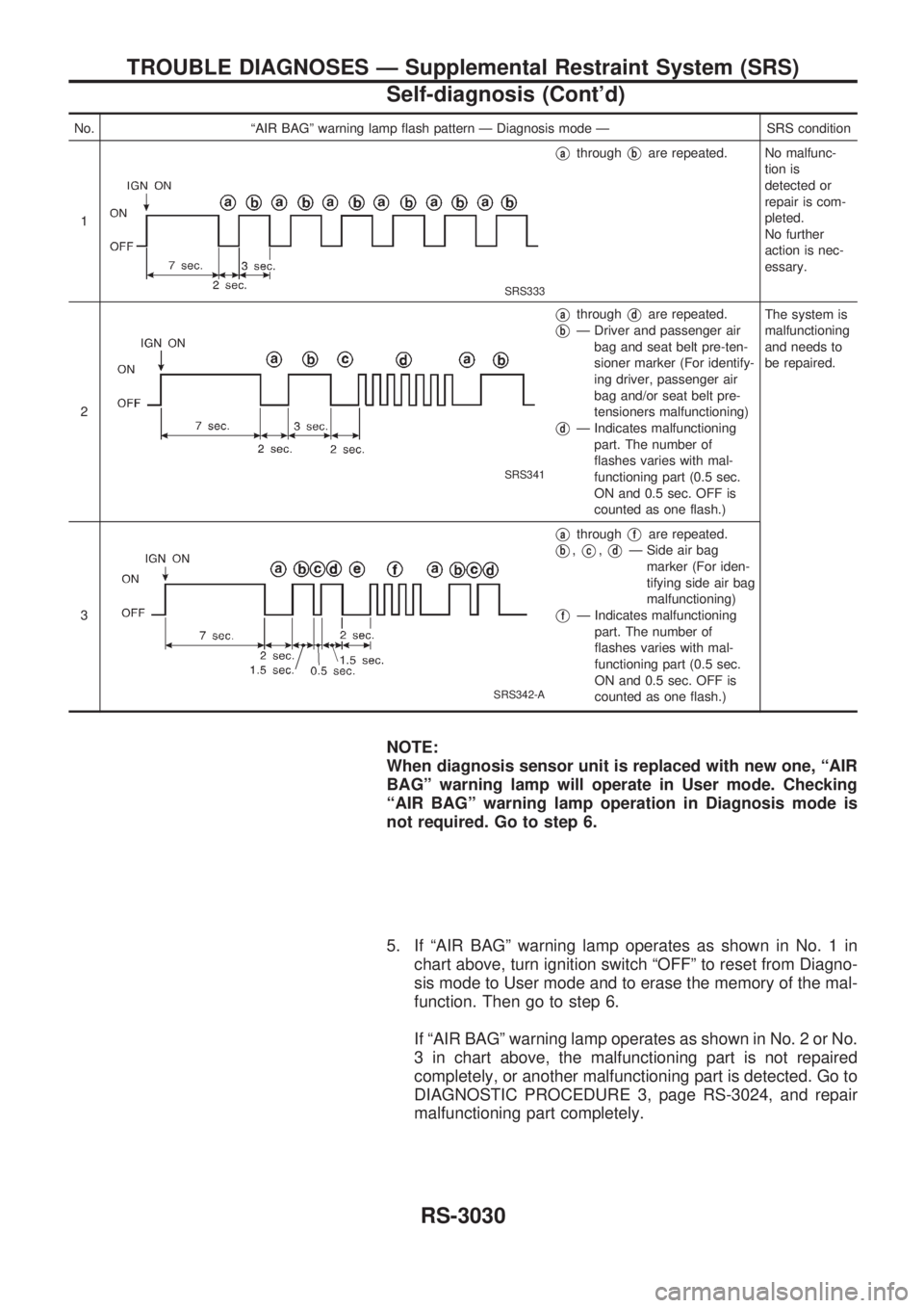
No. ªAIR BAGº warning lamp flash pattern Ð Diagnosis mode Ð SRS condition
1
SRS333
VathroughVbare repeated. No malfunc-
tion is
detected or
repair is com-
pleted.
No further
action is nec-
essary.
2
SRS341
VathroughVdare repeated.
VbÐ Driver and passenger air
bag and seat belt pre-ten-
sioner marker (For identify-
ing driver, passenger air
bag and/or seat belt pre-
tensioners malfunctioning)
VdÐ Indicates malfunctioning
part. The number of
flashes varies with mal-
functioning part (0.5 sec.
ON and 0.5 sec. OFF is
counted as one flash.)The system is
malfunctioning
and needs to
be repaired.
3
SRS342-A
VathroughVfare repeated.
Vb,Vc,VdÐ Side air bag
marker (For iden-
tifying side air bag
malfunctioning)
VfÐ Indicates malfunctioning
part. The number of
flashes varies with mal-
functioning part (0.5 sec.
ON and 0.5 sec. OFF is
counted as one flash.)
NOTE:
When diagnosis sensor unit is replaced with new one, ªAIR
BAGº warning lamp will operate in User mode. Checking
ªAIR BAGº warning lamp operation in Diagnosis mode is
not required. Go to step 6.
5. If ªAIR BAGº warning lamp operates as shown in No. 1 in
chart above, turn ignition switch ªOFFº to reset from Diagno-
sis mode to User mode and to erase the memory of the mal-
function. Then go to step 6.
If ªAIR BAGº warning lamp operates as shown in No. 2 or No.
3 in chart above, the malfunctioning part is not repaired
completely, or another malfunctioning part is detected. Go to
DIAGNOSTIC PROCEDURE 3, page RS-3024, and repair
malfunctioning part completely.
TROUBLE DIAGNOSES Ð Supplemental Restraint System (SRS)
Self-diagnosis (Cont'd)
RS-3030
Page 1104 of 1306
![NISSAN PICK-UP 2001 Repair Manual 5. Touch ªAIR BAGº.
6. Touch ªSELF-DIAG [PAST]º.
7. If diagnostic codes are displayed on ªSELF-DIAG [PAST]º,
go to step 10.
If no malfunction is detected on ªSELF-DIAG [PAST]º, touch
ªBACKº NISSAN PICK-UP 2001 Repair Manual 5. Touch ªAIR BAGº.
6. Touch ªSELF-DIAG [PAST]º.
7. If diagnostic codes are displayed on ªSELF-DIAG [PAST]º,
go to step 10.
If no malfunction is detected on ªSELF-DIAG [PAST]º, touch
ªBACKº](/manual-img/5/57372/w960_57372-1103.png)
5. Touch ªAIR BAGº.
6. Touch ªSELF-DIAG [PAST]º.
7. If diagnostic codes are displayed on ªSELF-DIAG [PAST]º,
go to step 10.
If no malfunction is detected on ªSELF-DIAG [PAST]º, touch
ªBACKº and go back to ªSELECT DIAG MODEº.
8. Touch ªTROUBLE DIAG RECORDº.
NOTE:
With ªTROUBLE DIAG RECORDº, diagnosis results previ-
ously erased by a reset operation can be displayed.
SRS771
SRS697
SHIA0181E
SRS702
SRS697
TROUBLE DIAGNOSES Ð Supplemental Restraint System (SRS)
Self-diagnosis (Cont'd)
RS-3033
Page 1243 of 1306
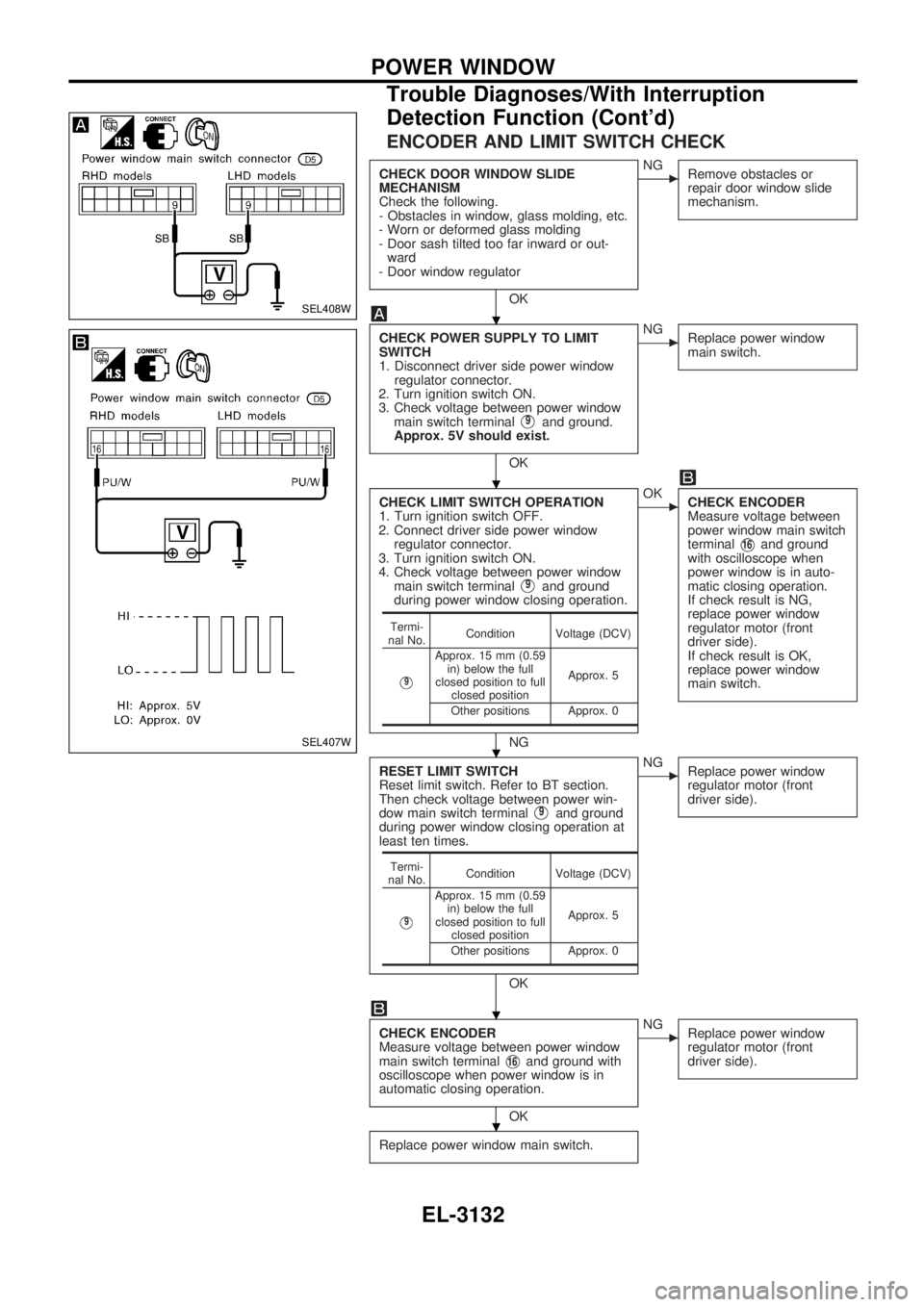
ENCODER AND LIMIT SWITCH CHECK
CHECK DOOR WINDOW SLIDE
MECHANISM
Check the following.
- Obstacles in window, glass molding, etc.
- Worn or deformed glass molding
- Door sash tilted too far inward or out-
ward
- Door window regulator
OK
cNG
Remove obstacles or
repair door window slide
mechanism.
CHECK POWER SUPPLY TO LIMIT
SWITCH
1. Disconnect driver side power window
regulator connector.
2. Turn ignition switch ON.
3. Check voltage between power window
main switch terminal
V9and ground.
Approx. 5V should exist.
OK
cNG
Replace power window
main switch.
CHECK LIMIT SWITCH OPERATION
1. Turn ignition switch OFF.
2. Connect driver side power window
regulator connector.
3. Turn ignition switch ON.
4. Check voltage between power window
main switch terminal
V9and ground
during power window closing operation.
NG
cOK
CHECK ENCODER
Measure voltage between
power window main switch
terminal
V16and ground
with oscilloscope when
power window is in auto-
matic closing operation.
If check result is NG,
replace power window
regulator motor (front
driver side).
If check result is OK,
replace power window
main switch.
RESET LIMIT SWITCH
Reset limit switch. Refer to BT section.
Then check voltage between power win-
dow main switch terminal
V9and ground
during power window closing operation at
least ten times.
OK
cNG
Replace power window
regulator motor (front
driver side).
CHECK ENCODER
Measure voltage between power window
main switch terminal
V16and ground with
oscilloscope when power window is in
automatic closing operation.
OK
cNG
Replace power window
regulator motor (front
driver side).
Replace power window main switch.
Termi-
nal No.Condition Voltage (DCV)
V9
Approx. 15 mm (0.59
in) below the full
closed position to full
closed positionApprox. 5
Other positions Approx. 0
Termi-
nal No.Condition Voltage (DCV)
V9
Approx. 15 mm (0.59
in) below the full
closed position to full
closed positionApprox. 5
Other positions Approx. 0
SEL408W
SEL407W
.
.
.
.
.
POWER WINDOW
Trouble Diagnoses/With Interruption
Detection Function (Cont'd)
EL-3132