Page 1048 of 3051
Basic Inspection (Models with Throttle Opener)NLEC1369Precaution:
Perform Basic Inspection without electrical or mechanical
loads applied;
+Headlamp switch is OFF,
On vehicle equipped with daytime light systems, set lighting
switch to the 1st position to light only small lamps.
+Air conditioner switch is OFF,
+Rear window defogger switch is OFF,
+Steering wheel is in the straight-ahead position, etc.
1 INSPECTION START
1. Check service records for any recent repairs that may indicate a related problem, or a current need for scheduled
maintenance.
2. Open engine hood and check the following:
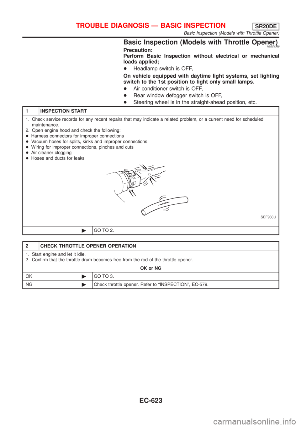
+Harness connectors for improper connections
+Vacuum hoses for splits, kinks and improper connections
+Wiring for improper connections, pinches and cuts
+Air cleaner clogging
+Hoses and ducts for leaks
SEF983U
©GO TO 2.
2 CHECK THROTTLE OPENER OPERATION
1. Start engine and let it idle.
2. Confirm that the throttle drum becomes free from the rod of the throttle opener.
OK or NG
OK©GO TO 3.
NG©Check throttle opener. Refer to ªINSPECTIONº, EC-579.
TROUBLE DIAGNOSIS Ð BASIC INSPECTIONSR20DE
Basic Inspection (Models with Throttle Opener)
EC-623
Page 1063 of 3051
Basic Inspection (Models without Throttle
Opener)
=NLEC1930Precaution:
Perform Basic Inspection without electrical or mechanical
loads applied;
+Headlamp switch is OFF,
+On vehicles equipped with daytime running light system, set
lighting switch to the 1st position to light only small lamps.
+Air conditioner switch is OFF,
+Rear window defogger switch is OFF,
+Steering wheel is in the straight-ahead position, etc.
1 INSPECTION START
1. Check service records for any recent repairs that may indicate a related problem, or the current need for scheduled
maintenance.
2. Open engine hood and check the following:
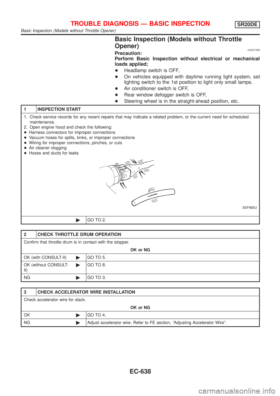
+Harness connectors for improper connections
+Vacuum hoses for splits, kinks, or improper connections
+Wiring for improper connections, pinches, or cuts
+Air cleaner clogging
+Hoses and ducts for leaks
SEF983U
©GO TO 2.
2 CHECK THROTTLE DRUM OPERATION
Confirm that throttle drum is in contact with the stopper.
OK or NG
OK (with CONSULT-II)©GO TO 5.
OK (without CONSULT-
II)©GO TO 8.
NG©GO TO 3.
3 CHECK ACCELERATOR WIRE INSTALLATION
Check accelerator wire for slack.
OK or NG
OK©GO TO 4.
NG©Adjust accelerator wire. Refer to FE section, ªAdjusting Accelerator Wireº.
TROUBLE DIAGNOSIS Ð BASIC INSPECTIONSR20DE
Basic Inspection (Models without Throttle Opener)
EC-638
Page 1289 of 3051
CONSULT-II Reference Value in Data Monitor
Mode
NLEC1580
MONITOR ITEM CONDITION SPECIFICATION
IACV-AAC/V+Engine: After warming up
+Air conditioner switch: OFF
+Shift lever: ªNº
+No-loadIdle 5 - 20 steps
2,000 rpm Ð
ECM Terminals and Reference ValueNLEC1581Specification data are reference values and are measured between each terminal and ground.
CAUTION:
Do not use ECM ground terminals when measuring input/output voltage. Doing so may result in dam-
age to the ECM's transistor. Use a ground other than ECM terminals, such as the ground.
TER-
MINAL
NO.WIRE
COLORITEM CONDITION DATA (DC Voltage)
6
7
15
16BR
LG
GY/L
ORIACV-AAC valve[Engine is running]
+Warm-up condition
+Idle speed0.1 - 14V
On Board Diagnosis LogicNLEC1582
DTC No. Malfunction is detected when ... Check Items (Possible Cause)
P0505+An improper voltage signal is sent to ECM through the
valve.+Harness or connectors
(The IACV-AAC valve circuit is open.)
+IACV-AAC valve
SEF058Y
DTC Confirmation ProcedureNLEC1583NOTE:
+If ªDTC Confirmation Procedureº has been previously
conducted, always turn ignition switch ªOFFº and wait at least
10 seconds before conducting the next test.
+If the target idle speed is out of the specified value, per-
form ªIdle Air Volume Learningº, EC-581, before conduct-
ing ªDTC Confirmation Procedureº. For the target idle
speed, refer to ªService Data and Specifications (SDS)º,
EC-1062.
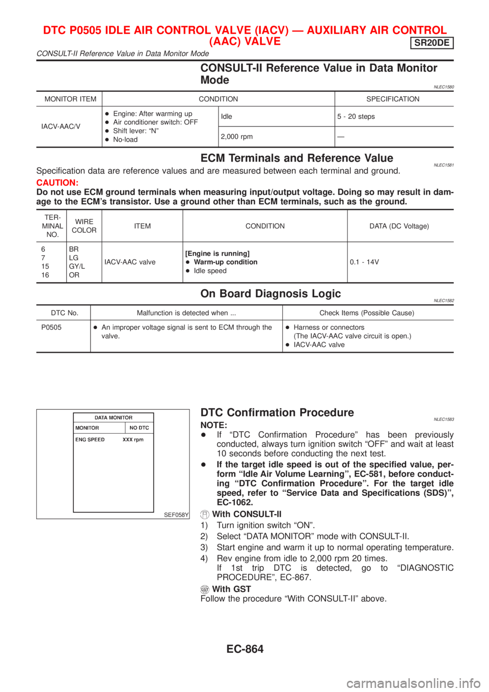
With CONSULT-II
1) Turn ignition switch ªONº.
2) Select ªDATA MONITORº mode with CONSULT-II.
3) Start engine and warm it up to normal operating temperature.
4) Rev engine from idle to 2,000 rpm 20 times.
If 1st trip DTC is detected, go to ªDIAGNOSTIC
PROCEDUREº, EC-867.
With GST
Follow the procedure ªWith CONSULT-IIº above.
DTC P0505 IDLE AIR CONTROL VALVE (IACV) Ð AUXILIARY AIR CONTROL
(AAC) VALVE
SR20DE
CONSULT-II Reference Value in Data Monitor Mode
EC-864
Page 1487 of 3051
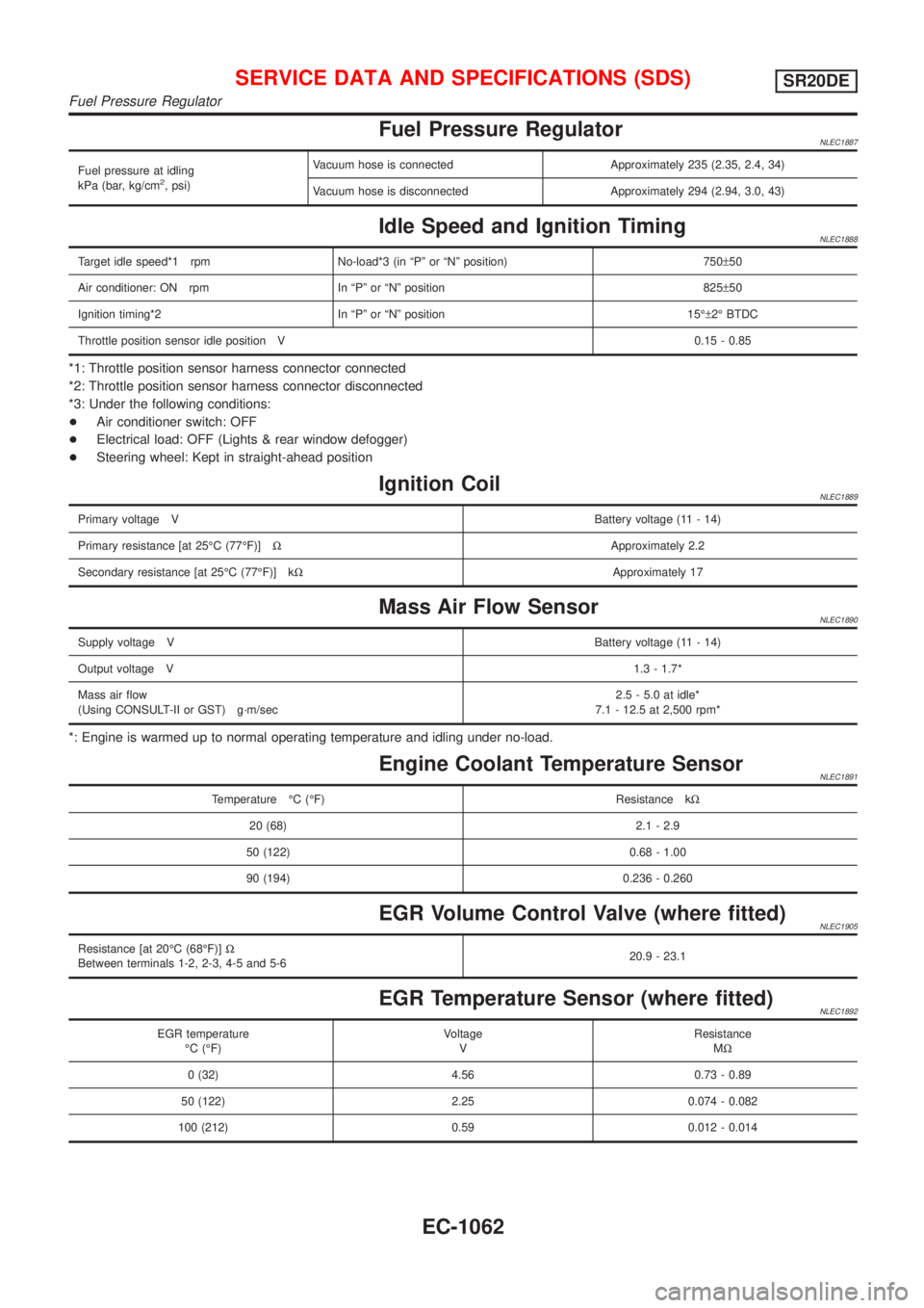
Fuel Pressure RegulatorNLEC1887
Fuel pressure at idling
kPa (bar, kg/cm2, psi)Vacuum hose is connected Approximately 235 (2.35, 2.4, 34)
Vacuum hose is disconnected Approximately 294 (2.94, 3.0, 43)
Idle Speed and Ignition TimingNLEC1888
Target idle speed*1 rpm No-load*3 (in ªPº or ªNº position) 750±50
Air conditioner: ON rpm In ªPº or ªNº position 825±50
Ignition timing*2 In ªPº or ªNº position 15ɱ2É BTDC
Throttle position sensor idle position V0.15 - 0.85
*1: Throttle position sensor harness connector connected
*2: Throttle position sensor harness connector disconnected
*3: Under the following conditions:
+Air conditioner switch: OFF
+Electrical load: OFF (Lights & rear window defogger)
+Steering wheel: Kept in straight-ahead position
Ignition CoilNLEC1889
Primary voltage VBattery voltage (11 - 14)
Primary resistance [at 25ÉC (77ÉF)]WApproximately 2.2
Secondary resistance [at 25ÉC (77ÉF)] kWApproximately 17
Mass Air Flow SensorNLEC1890
Supply voltage VBattery voltage (11 - 14)
Output voltage V1.3 - 1.7*
Mass air flow
(Using CONSULT-II or GST) g´m/sec2.5 - 5.0 at idle*
7.1 - 12.5 at 2,500 rpm*
*: Engine is warmed up to normal operating temperature and idling under no-load.
Engine Coolant Temperature SensorNLEC1891
Temperature ÉC (ÉF) Resistance kW
20 (68) 2.1 - 2.9
50 (122) 0.68 - 1.00
90 (194) 0.236 - 0.260
EGR Volume Control Valve (where fitted)NLEC1905
Resistance [at 20ÉC (68ÉF)]W
Between terminals 1-2, 2-3, 4-5 and 5-620.9 - 23.1
EGR Temperature Sensor (where fitted)NLEC1892
EGR temperature
ÉC (ÉF)Voltage
VResistance
MW
0 (32) 4.56 0.73 - 0.89
50 (122) 2.25 0.074 - 0.082
100 (212) 0.59 0.012 - 0.014
SERVICE DATA AND SPECIFICATIONS (SDS)SR20DE
Fuel Pressure Regulator
EC-1062
Page 1488 of 3051
![NISSAN ALMERA TINO 2001 Service Repair Manual Fuel PumpNLEC1893
Resistance [at 25ÉC (77ÉF)]W0.2 - 5.0
IACV-AAC ValveNLEC1894
Resistance [at 20ÉC (68ÉF)]W20±24
InjectorNLEC1895
Resistance [at 20ÉC (68ÉF)]W13.1 ± 16.0
ResistorNLEC1896
Resis NISSAN ALMERA TINO 2001 Service Repair Manual Fuel PumpNLEC1893
Resistance [at 25ÉC (77ÉF)]W0.2 - 5.0
IACV-AAC ValveNLEC1894
Resistance [at 20ÉC (68ÉF)]W20±24
InjectorNLEC1895
Resistance [at 20ÉC (68ÉF)]W13.1 ± 16.0
ResistorNLEC1896
Resis](/manual-img/5/57352/w960_57352-1487.png)
Fuel PumpNLEC1893
Resistance [at 25ÉC (77ÉF)]W0.2 - 5.0
IACV-AAC ValveNLEC1894
Resistance [at 20ÉC (68ÉF)]W20±24
InjectorNLEC1895
Resistance [at 20ÉC (68ÉF)]W13.1 ± 16.0
ResistorNLEC1896
Resistance [at 25ÉC (77ÉF)] kWApproximately 5
Throttle Position SensorNLEC1897
Throttle valve conditionsVoltage (at normal operating temperature, engine off, ignition switch ON,
throttle opener disengaged)
Completely closed (a)0.15 - 0.85V
Partially openBetween (a) and (b)
Completely open (b)3.5 - 4.7V
Heated Oxygen Sensor 1 (Front) HeaterNLEC1898
Resistance [at 25ÉC (77ÉF)]W2.3 - 4.3
Intake Air Temperature SensorNLEC1900
Temperature ÉC (ÉF) Resistance kW
20 (68) 2.1 - 2.9
80 (176) 0.27 - 0.38
EVAP Canister Purge Volume Control ValveNLEC1901
Resistance [at 20ÉC (68ÉF)]W31-35
Heated Oxygen Sensor 2 (Rear) HeaterNLEC1902
Resistance [at 25ÉC (77ÉF)]W2.3 - 4.3
Crankshaft Position Sensor (OBD)NLEC1903
Resistance [at 20ÉC (68ÉF)]W166 - 204
SERVICE DATA AND SPECIFICATIONS (SDS)SR20DE
Fuel Pump
EC-1063
Page 1491 of 3051
Precautions for Supplemental Restraint System
(SRS) ªAIR BAGº and ªSEAT BELT
PRE-TENSIONERº
NLEC1263The Supplemental Restraint System ªAIR BAGº and ªSEAT BELT PRE-TENSIONERº, used along with a seat
belt, help to reduce the risk or severity of injury to the driver and front passenger in a frontal collision. The
Supplemental Restraint System consists of air bag modules (located in the center of the steering wheel and
on the instrument panel on the passenger side), seat belt pre-tensioners, a diagnosis sensor unit, warning
lamp, wiring harness and spiral cable.
In addition to the supplemental air bag modules for a frontal collision, the supplemental side air bag used along
with the seat belt helps to reduce the risk or severity of injury to the driver and front passenger in a side col-
lision. The supplemental side air bag consists of air bag modules (located in the outer side of front seats),
satellite sensor, diagnosis sensor unit (one of components of supplemental air bags for a frontal collision),
wiring harness, warning lamp (one of components of supplemental air bags for a frontal collision). Information
necessary to service the system safely is included in theRS sectionof this Service Manual.
WARNING:
+To avoid rendering the SRS inoperative, which could increase the risk of personal injury or death
in the event of a collision which would result in air bag inflation, all maintenance must be performed
by an authorized NISSAN dealer.
+Improper maintenance, including incorrect removal and installation of the SRS, can lead to per-
sonal injury caused by unintentional activation of the system.
+Do not use electrical test equipment on any circuit related to the SRS unless instructed to in this
Service Manual. SRS wiring harnesses can be identified with yellow harness connector (and with
yellow harness protector or yellow insulation tape before the harness connectors).
SEF706Y
Engine Fuel & Emission Control SystemNLEC0602+Always use a 12 volt battery as power source.
+Do not attempt to disconnect battery cable while engine is
running.
+Before connecting or disconnecting the ECM harness
connector, turn ignition switch OFF and disconnect nega-
tive battery terminal. Failure to do so may damage the
ECM because battery voltage is applied to ECM even if
ignition switch is turned off.
+Before removing parts, turn off ignition switch and then
disconnect battery ground cable.
SEC220B
+Do not disassemble ECM.
+If a battery terminal is disconnected, the memory will
return to the ECM value.
The ECM will now start to self-control at its initial value.
Engine operation can vary slightly when the terminal is
disconnected. However, this is not an indication of a prob-
lem. Do not replace parts because of a slight variation.
PRECAUTIONSYD22DDTI
Precautions for Supplemental Restraint System (SRS) ªAIR BAGº and ªSEAT BELT PRE-TENSIONERº
EC-1066
Page 1495 of 3051
Special Service ToolsNLEC0605
Tool number
Tool nameDescription
KV111060S0
Removal/Installation tool
kit for fuel injection pump
NT814
KV109E0010
Break-out box
NT825
KV109E0050
Y-cable adapter
NT826
PREPARATIONYD22DDTI
Special Service Tools
EC-1070
Page 1508 of 3051
Injection Tube and Injection Nozzle
REMOVAL AND INSTALLATIONNLEC0618CAUTION:
+Do not disassemble injection nozzle assembly. If NG,
replace injection nozzle assembly.
+Plug flare nut with a cap or rag so that no dust enters the
nozzle. Cover nozzle tip to protect it.
JEF443Z
JEF340Y
Injection TubeNLEC0618S01RemovalNLEC0618S01011. Mark the cylinder Nos. to the injection tubes, then disconnect
them.
+Marking should be made at proper locations and by the
proper method, so that they are not erased by fuel, etc.
2. Remove the clamps, then disconnect the tubes one by one.
+The intake manifold is removed for explanation in the figure.
BASIC SERVICE PROCEDUREYD22DDTI
Injection Tube and Injection Nozzle
EC-1083