2001 NISSAN ALMERA TINO service
[x] Cancel search: servicePage 2134 of 3051
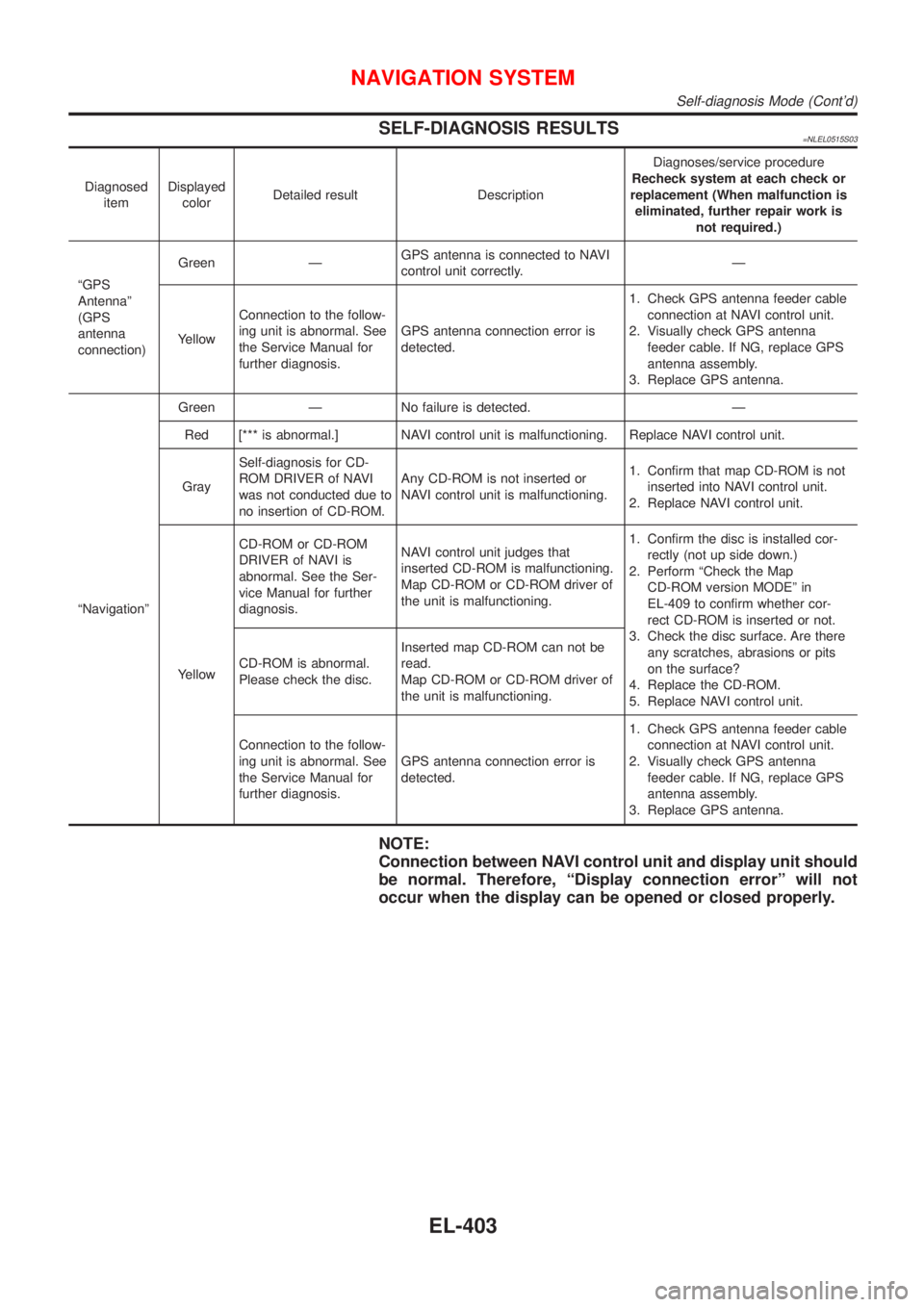
SELF-DIAGNOSIS RESULTS=NLEL0515S03
Diagnosed
itemDisplayed
colorDetailed result DescriptionDiagnoses/service procedure
Recheck system at each check or
replacement (When malfunction is
eliminated, further repair work is
not required.)
ªGPS
Antennaº
(GPS
antenna
connection)Green ÐGPS antenna is connected to NAVI
control unit correctly.Ð
YellowConnection to the follow-
ing unit is abnormal. See
the Service Manual for
further diagnosis.GPS antenna connection error is
detected.1. Check GPS antenna feeder cable
connection at NAVI control unit.
2. Visually check GPS antenna
feeder cable. If NG, replace GPS
antenna assembly.
3. Replace GPS antenna.
ªNavigationºGreen Ð No failure is detected. Ð
Red [*** is abnormal.] NAVI control unit is malfunctioning. Replace NAVI control unit.
GraySelf-diagnosis for CD-
ROM DRIVER of NAVI
was not conducted due to
no insertion of CD-ROM.Any CD-ROM is not inserted or
NAVI control unit is malfunctioning.1. Confirm that map CD-ROM is not
inserted into NAVI control unit.
2. Replace NAVI control unit.
YellowCD-ROM or CD-ROM
DRIVER of NAVI is
abnormal. See the Ser-
vice Manual for further
diagnosis.NAVI control unit judges that
inserted CD-ROM is malfunctioning.
Map CD-ROM or CD-ROM driver of
the unit is malfunctioning.1. Confirm the disc is installed cor-
rectly (not up side down.)
2. Perform ªCheck the Map
CD-ROM version MODEº in
EL-409 to confirm whether cor-
rect CD-ROM is inserted or not.
3. Check the disc surface. Are there
any scratches, abrasions or pits
on the surface?
4. Replace the CD-ROM.
5. Replace NAVI control unit. CD-ROM is abnormal.
Please check the disc.Inserted map CD-ROM can not be
read.
Map CD-ROM or CD-ROM driver of
the unit is malfunctioning.
Connection to the follow-
ing unit is abnormal. See
the Service Manual for
further diagnosis.GPS antenna connection error is
detected.1. Check GPS antenna feeder cable
connection at NAVI control unit.
2. Visually check GPS antenna
feeder cable. If NG, replace GPS
antenna assembly.
3. Replace GPS antenna.
NOTE:
Connection between NAVI control unit and display unit should
be normal. Therefore, ªDisplay connection errorº will not
occur when the display can be opened or closed properly.
NAVIGATION SYSTEM
Self-diagnosis Mode (Cont'd)
EL-403
Page 2137 of 3051
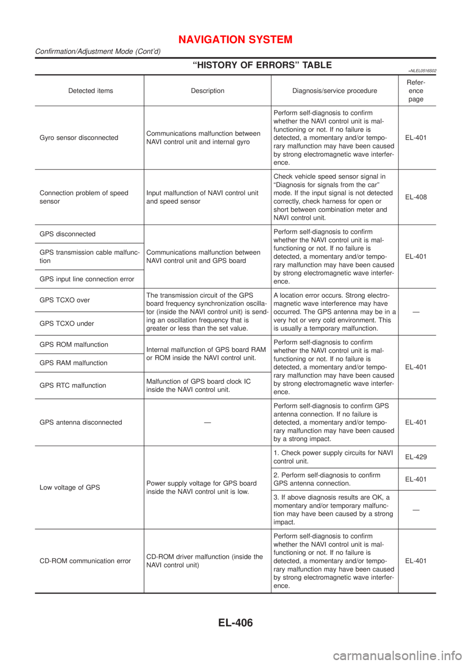
ªHISTORY OF ERRORSº TABLE=NLEL0516S02
Detected items Description Diagnosis/service procedureRefer-
ence
page
Gyro sensor disconnectedCommunications malfunction between
NAVI control unit and internal gyroPerform self-diagnosis to confirm
whether the NAVI control unit is mal-
functioning or not. If no failure is
detected, a momentary and/or tempo-
rary malfunction may have been caused
by strong electromagnetic wave interfer-
ence.EL-401
Connection problem of speed
sensorInput malfunction of NAVI control unit
and speed sensorCheck vehicle speed sensor signal in
ªDiagnosis for signals from the carº
mode. If the input signal is not detected
correctly, check harness for open or
short between combination meter and
NAVI control unit.EL-408
GPS disconnected
Communications malfunction between
NAVI control unit and GPS boardPerform self-diagnosis to confirm
whether the NAVI control unit is mal-
functioning or not. If no failure is
detected, a momentary and/or tempo-
rary malfunction may have been caused
by strong electromagnetic wave interfer-
ence.EL-401 GPS transmission cable malfunc-
tion
GPS input line connection error
GPS TCXO overThe transmission circuit of the GPS
board frequency synchronization oscilla-
tor (inside the NAVI control unit) is send-
ing an oscillation frequency that is
greater or less than the set value.A location error occurs. Strong electro-
magnetic wave interference may have
occurred. The GPS antenna may be in a
very hot or very cold environment. This
is usually a temporary malfunction.Ð
GPS TCXO under
GPS ROM malfunction
Internal malfunction of GPS board RAM
or ROM inside the NAVI control unit.Perform self-diagnosis to confirm
whether the NAVI control unit is mal-
functioning or not. If no failure is
detected, a momentary and/or tempo-
rary malfunction may have been caused
by strong electromagnetic wave interfer-
ence.EL-401 GPS RAM malfunction
GPS RTC malfunctionMalfunction of GPS board clock IC
inside the NAVI control unit.
GPS antenna disconnected ÐPerform self-diagnosis to confirm GPS
antenna connection. If no failure is
detected, a momentary and/or tempo-
rary malfunction may have been caused
by a strong impact.EL-401
Low voltage of GPSPower supply voltage for GPS board
inside the NAVI control unit is low.1. Check power supply circuits for NAVI
control unit.EL-429
2. Perform self-diagnosis to confirm
GPS antenna connection.EL-401
3. If above diagnosis results are OK, a
momentary and/or temporary malfunc-
tion may have been caused by a strong
impact.Ð
CD-ROM communication errorCD-ROM driver malfunction (inside the
NAVI control unit)Perform self-diagnosis to confirm
whether the NAVI control unit is mal-
functioning or not. If no failure is
detected, a momentary and/or tempo-
rary malfunction may have been caused
by strong electromagnetic wave interfer-
ence.EL-401
NAVIGATION SYSTEM
Confirmation/Adjustment Mode (Cont'd)
EL-406
Page 2138 of 3051
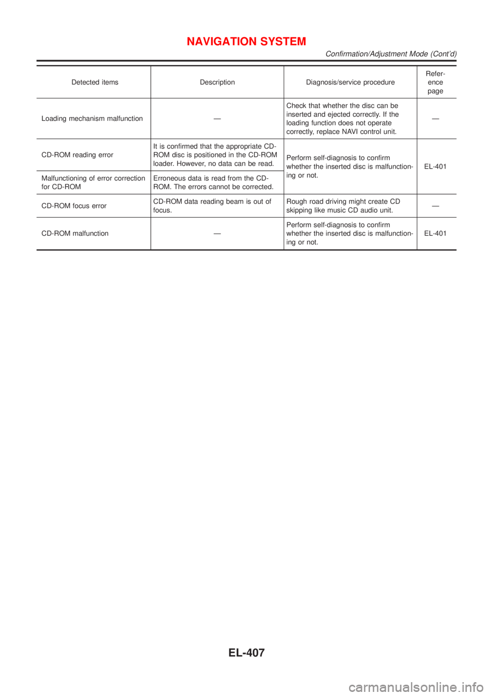
Detected items Description Diagnosis/service procedureRefer-
ence
page
Loading mechanism malfunction ÐCheck that whether the disc can be
inserted and ejected correctly. If the
loading function does not operate
correctly, replace NAVI control unit.Ð
CD-ROM reading errorIt is confirmed that the appropriate CD-
ROM disc is positioned in the CD-ROM
loader. However, no data can be read.Perform self-diagnosis to confirm
whether the inserted disc is malfunction-
ing or not.EL-401
Malfunctioning of error correction
for CD-ROMErroneous data is read from the CD-
ROM. The errors cannot be corrected.
CD-ROM focus errorCD-ROM data reading beam is out of
focus.Rough road driving might create CD
skipping like music CD audio unit.Ð
CD-ROM malfunction ÐPerform self-diagnosis to confirm
whether the inserted disc is malfunction-
ing or not.EL-401
NAVIGATION SYSTEM
Confirmation/Adjustment Mode (Cont'd)
EL-407
Page 2156 of 3051
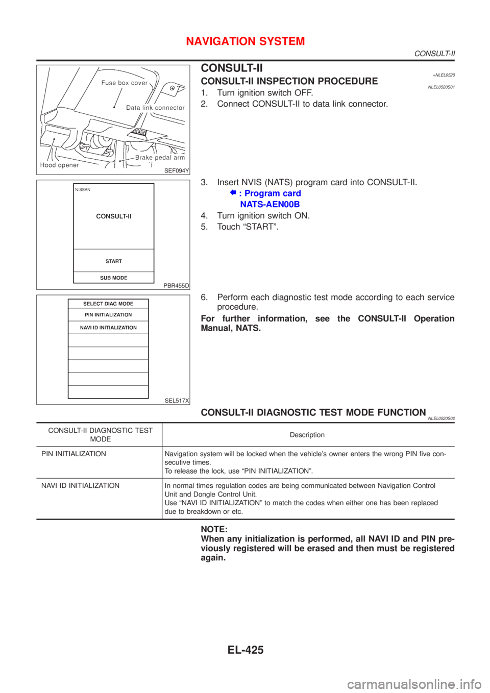
SEF094Y
CONSULT-II=NLEL0520CONSULT-II INSPECTION PROCEDURENLEL0520S011. Turn ignition switch OFF.
2. Connect CONSULT-II to data link connector.
PBR455D
3. Insert NVIS (NATS) program card into CONSULT-II.
: Program card
NATS-AEN00B
4. Turn ignition switch ON.
5. Touch ªSTARTº.
SEL517X
6. Perform each diagnostic test mode according to each service
procedure.
For further information, see the CONSULT-II Operation
Manual, NATS.
CONSULT-II DIAGNOSTIC TEST MODE FUNCTIONNLEL0520S02
CONSULT-II DIAGNOSTIC TEST
MODEDescription
PIN INITIALIZATION Navigation system will be locked when the vehicle's owner enters the wrong PIN five con-
secutive times.
To release the lock, use ªPIN INITIALIZATIONº.
NAVI ID INITIALIZATION In normal times regulation codes are being communicated between Navigation Control
Unit and Dongle Control Unit.
Use ªNAVI ID INITIALIZATIONº to match the codes when either one has been replaced
due to breakdown or etc.
NOTE:
When any initialization is performed, all NAVI ID and PIN pre-
viously registered will be erased and then must be registered
again.
NAVIGATION SYSTEM
CONSULT-II
EL-425
Page 2157 of 3051
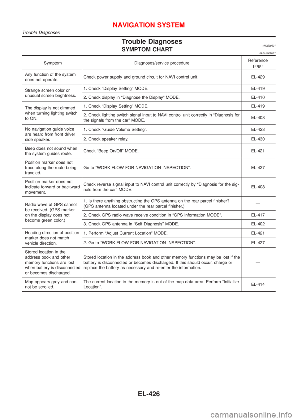
Trouble Diagnoses=NLEL0521SYMPTOM CHARTNLEL0521S01
Symptom Diagnoses/service procedureReference
page
Any function of the system
does not operate.Check power supply and ground circuit for NAVI control unit. EL-429
Strange screen color or
unusual screen brightness.1. Check ªDisplay Settingº MODE. EL-419
2. Check display in ªDiagnose the Displayº MODE. EL-410
The display is not dimmed
when turning lighting switch
to ON.1. Check ªDisplay Settingº MODE. EL-419
2. Check lighting switch signal input to NAVI control unit correctly in ªDiagnosis for
the signals from the carº MODE.EL-408
No navigation guide voice
are heard from front driver
side speaker.1. Check ªGuide Volume Settingº. EL-423
2. Check speaker relay. EL-430
Beep does not sound when
the system guides route.Check ªBeep On/Offº MODE. EL-421
Position marker does not
trace along the route being
traveled.Go to ªWORK FLOW FOR NAVIGATION INSPECTIONº. EL-427
Position marker does not
indicate forward or backward
movement.Check reverse signal input to NAVI control unit correctly by ªDiagnosis for the sig-
nals from the carº MODE.EL-408
Radio wave of GPS cannot
be received. (GPS marker
on the display does not
become green color.)1. Is there anything obstructing the GPS antenna on the rear parcel finisher?
(GPS antenna located under the rear parcel finisher.)Ð
2. Check GPS radio wave receive condition in ªGPS Information MODEº. EL-417
3. Check GPS antenna in ªSelf Diagnosisº MODE. EL-402
Heading direction of position
marker does not match
vehicle direction.1. Perform ªAdjust Current Locationº MODE. EL-421
2. Go to ªWORK FLOW FOR NAVIGATION INSPECTIONº. EL-427
Stored location in the
address book and other
memory functions are lost
when battery is disconnected
or becomes discharged.Stored location in the address book and other memory functions may be lost if the
battery is disconnected or becomes discharged. If this should occur, charge or
replace the battery as necessary and re-enter the information.Ð
Map appears grey and can-
not be scrolled.The current location in the memory is out of the map data area. Perform ªInitialize
Locationº.EL-414
NAVIGATION SYSTEM
Trouble Diagnoses
EL-426
Page 2165 of 3051
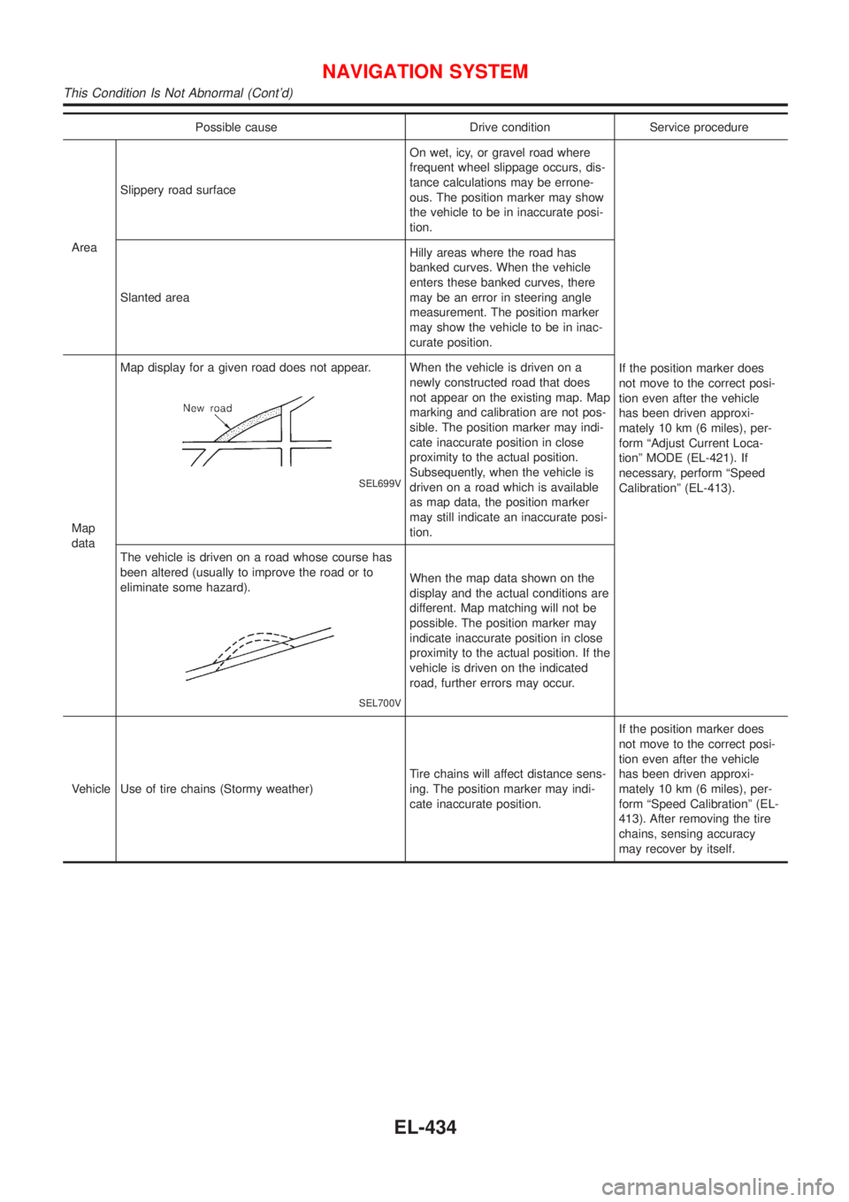
Possible cause Drive condition Service procedure
AreaSlippery road surfaceOn wet, icy, or gravel road where
frequent wheel slippage occurs, dis-
tance calculations may be errone-
ous. The position marker may show
the vehicle to be in inaccurate posi-
tion.
If the position marker does
not move to the correct posi-
tion even after the vehicle
has been driven approxi-
mately 10 km (6 miles), per-
form ªAdjust Current Loca-
tionº MODE (EL-421). If
necessary, perform ªSpeed
Calibrationº (EL-413). Slanted areaHilly areas where the road has
banked curves. When the vehicle
enters these banked curves, there
may be an error in steering angle
measurement. The position marker
may show the vehicle to be in inac-
curate position.
Map
dataMap display for a given road does not appear.
SEL699V
When the vehicle is driven on a
newly constructed road that does
not appear on the existing map. Map
marking and calibration are not pos-
sible. The position marker may indi-
cate inaccurate position in close
proximity to the actual position.
Subsequently, when the vehicle is
driven on a road which is available
as map data, the position marker
may still indicate an inaccurate posi-
tion.
The vehicle is driven on a road whose course has
been altered (usually to improve the road or to
eliminate some hazard).
SEL700V
When the map data shown on the
display and the actual conditions are
different. Map matching will not be
possible. The position marker may
indicate inaccurate position in close
proximity to the actual position. If the
vehicle is driven on the indicated
road, further errors may occur.
Vehicle Use of tire chains (Stormy weather)Tire chains will affect distance sens-
ing. The position marker may indi-
cate inaccurate position.If the position marker does
not move to the correct posi-
tion even after the vehicle
has been driven approxi-
mately 10 km (6 miles), per-
form ªSpeed Calibrationº (EL-
413). After removing the tire
chains, sensing accuracy
may recover by itself.
NAVIGATION SYSTEM
This Condition Is Not Abnormal (Cont'd)
EL-434
Page 2166 of 3051
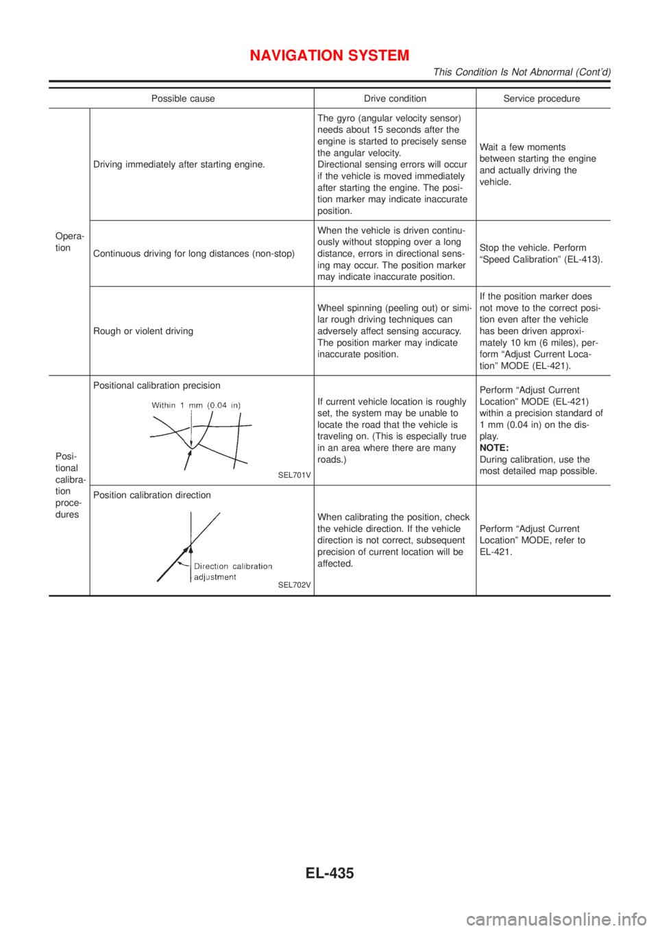
Possible cause Drive condition Service procedure
Opera-
tionDriving immediately after starting engine.The gyro (angular velocity sensor)
needs about 15 seconds after the
engine is started to precisely sense
the angular velocity.
Directional sensing errors will occur
if the vehicle is moved immediately
after starting the engine. The posi-
tion marker may indicate inaccurate
position.Wait a few moments
between starting the engine
and actually driving the
vehicle.
Continuous driving for long distances (non-stop)When the vehicle is driven continu-
ously without stopping over a long
distance, errors in directional sens-
ing may occur. The position marker
may indicate inaccurate position.Stop the vehicle. Perform
ªSpeed Calibrationº (EL-413).
Rough or violent drivingWheel spinning (peeling out) or simi-
lar rough driving techniques can
adversely affect sensing accuracy.
The position marker may indicate
inaccurate position.If the position marker does
not move to the correct posi-
tion even after the vehicle
has been driven approxi-
mately 10 km (6 miles), per-
form ªAdjust Current Loca-
tionº MODE (EL-421).
Posi-
tional
calibra-
tion
proce-
duresPositional calibration precision
SEL701V
If current vehicle location is roughly
set, the system may be unable to
locate the road that the vehicle is
traveling on. (This is especially true
in an area where there are many
roads.)Perform ªAdjust Current
Locationº MODE (EL-421)
within a precision standard of
1 mm (0.04 in) on the dis-
play.
NOTE:
During calibration, use the
most detailed map possible.
Position calibration direction
SEL702V
When calibrating the position, check
the vehicle direction. If the vehicle
direction is not correct, subsequent
precision of current location will be
affected.Perform ªAdjust Current
Locationº MODE, refer to
EL-421.
NAVIGATION SYSTEM
This Condition Is Not Abnormal (Cont'd)
EL-435
Page 2167 of 3051
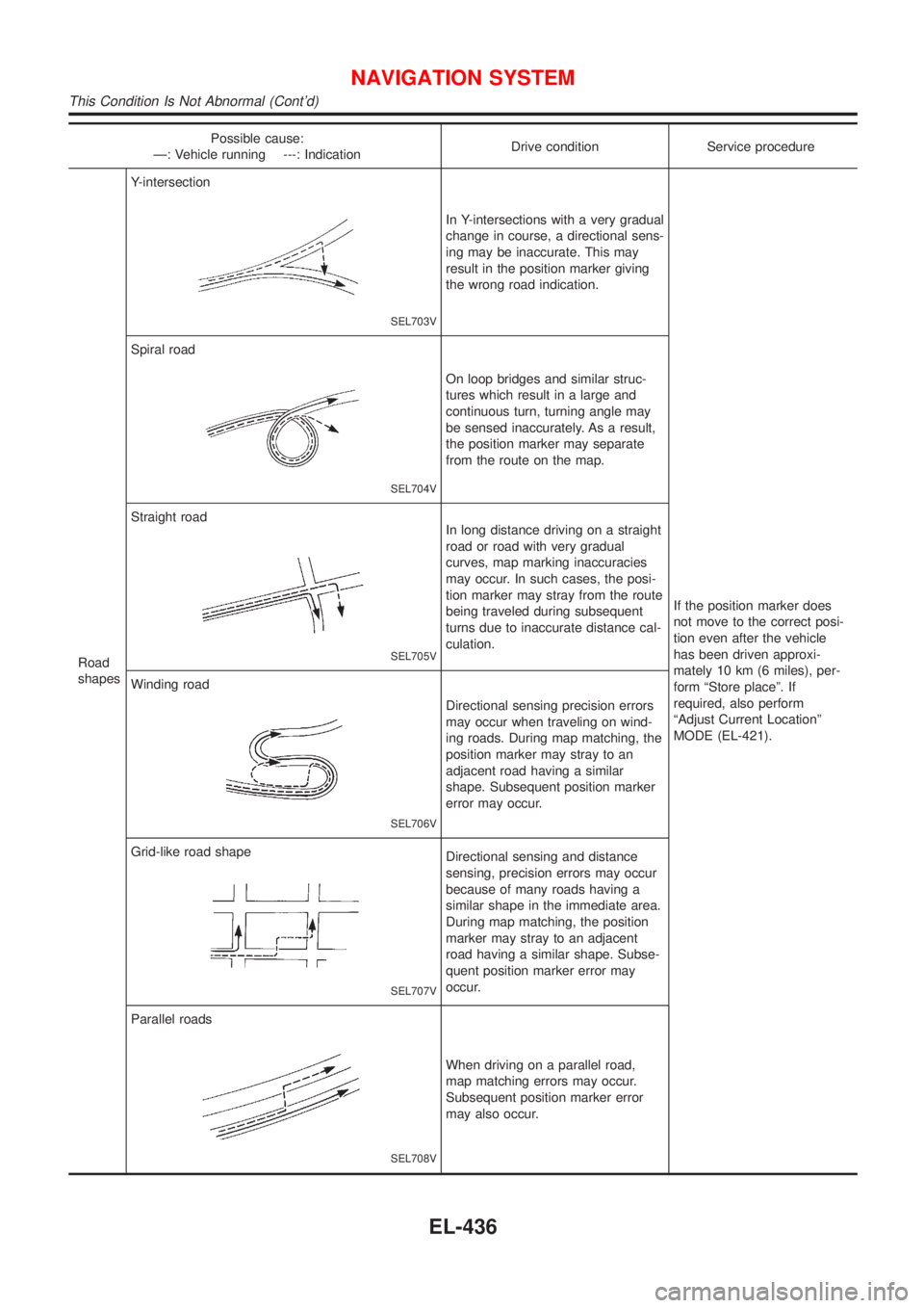
Possible cause:
Ð: Vehicle running ---: IndicationDrive condition Service procedure
Road
shapesY-intersection
SEL703V
In Y-intersections with a very gradual
change in course, a directional sens-
ing may be inaccurate. This may
result in the position marker giving
the wrong road indication.
If the position marker does
not move to the correct posi-
tion even after the vehicle
has been driven approxi-
mately 10 km (6 miles), per-
form ªStore placeº. If
required, also perform
ªAdjust Current Locationº
MODE (EL-421). Spiral road
SEL704V
On loop bridges and similar struc-
tures which result in a large and
continuous turn, turning angle may
be sensed inaccurately. As a result,
the position marker may separate
from the route on the map.
Straight road
SEL705V
In long distance driving on a straight
road or road with very gradual
curves, map marking inaccuracies
may occur. In such cases, the posi-
tion marker may stray from the route
being traveled during subsequent
turns due to inaccurate distance cal-
culation.
Winding road
SEL706V
Directional sensing precision errors
may occur when traveling on wind-
ing roads. During map matching, the
position marker may stray to an
adjacent road having a similar
shape. Subsequent position marker
error may occur.
Grid-like road shape
SEL707V
Directional sensing and distance
sensing, precision errors may occur
because of many roads having a
similar shape in the immediate area.
During map matching, the position
marker may stray to an adjacent
road having a similar shape. Subse-
quent position marker error may
occur.
Parallel roads
SEL708V
When driving on a parallel road,
map matching errors may occur.
Subsequent position marker error
may also occur.
NAVIGATION SYSTEM
This Condition Is Not Abnormal (Cont'd)
EL-436