2001 NISSAN ALMERA TINO service
[x] Cancel search: servicePage 1735 of 3051
Supplemental Restraint System (SRS) ªAIR
BAGº and ªSEAT BELT PRE-TENSIONERº
NLEL0001The Supplemental Restraint System such as ªAIR BAGº and ªSEAT BELT PRE-TENSIONERº used along with
a seat belt, helps to reduce the risk or severity of injury to the driver and front passenger for certain types of
collision. The SRS system composition which is available to NISSAN MODEL V10 is as follows (The compo-
sition varies according to the destination and optional equipment.):
+For a frontal collision
The Supplemental Restraint System consists of driver air bag module (located in the center of the steer-
ing wheel), front passenger air bag module (located on the instrument panel on passenger side), front seat
belt pre-tensioners, a diagnosis sensor unit, warning lamp, wiring harness and spiral cable.
+For a side collision
The Supplemental Restraint System consists of front side air bag module (located in the outer side of front
seat), side air bag (satellite) sensor, diagnosis sensor unit (one of components of air bags for a frontal
collision), wiring harness, warning lamp (one of components of air bags for a frontal collision).
Information necessary to service the system safely is included in theRS sectionof this Service Manual.
WARNING:
+To avoid rendering the SRS inoperative, which could increase the risk of personal injury or death
in the event of a collision which would result in air bag inflation, all maintenance should be per-
formed by an authorized NISSAN dealer.
+Improper maintenance, including incorrect removal and installation of the SRS, can lead to per-
sonal injury caused by unintentional activation of the system. For removal of Spiral Cable and Air
Bag Module, see the RS section.
+Do not use electrical test equipment on any circuit related to the SRS unless instructed to in this
Service Manual. Spiral cable and wiring harnesses covered with yellow insulation tape either just
before the harness connectors or for the complete harness are related to the SRS.
Wiring Diagrams and Trouble DiagnosisNLEL0002When you read wiring diagrams, refer to the following:
+Refer to GI-11, ªHOW TO READ WIRING DIAGRAMSº
+Refer to EL-10, ªPOWER SUPPLY ROUTINGº for power distribution circuit
When you perform trouble diagnosis, refer to the following:
+Refer to GI-32, ªHOW TO FOLLOW TEST GROUP IN TROUBLE DIAGNOSISº
+Refer to GI-21, ªHOW TO PERFORM EFFICIENT DIAGNOSIS FOR AN ELECTRICAL INCIDENTº
Check for any Service bulletins before servicing the vehicle.
PRECAUTIONS
Supplemental Restraint System (SRS) ªAIR BAGº and ªSEAT BELT PRE-TENSIONERº
EL-4
Page 1872 of 3051
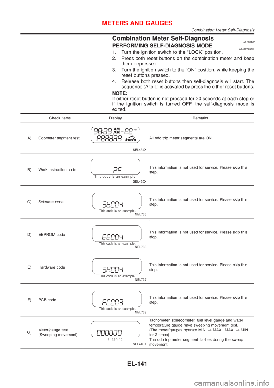
Combination Meter Self-DiagnosisNLEL0447PERFORMING SELF-DIAGNOSIS MODENLEL0447S011. Turn the ignition switch to the ªLOCKº position.
2. Press both reset buttons on the combination meter and keep
them depressed.
3. Turn the ignition switch to the ªONº position, while keeping the
reset buttons pressed.
4. Release both reset buttons then self-diagnosis will start. The
sequence (A to L) is activated by press the either reset buttons.
NOTE:
If either reset button is not pressed for 20 seconds at each step or
if the ignition switch is turned OFF, the self-diagnosis mode is
exited.
Check items Display Remarks
A) Odometer segment test
SEL434X
All odo trip meter segments are ON.
B) Work instruction code
SEL435X
This information is not used for service. Please skip this
step.
C) Software code
NEL735
This information is not used for service. Please skip this
step.
D) EEPROM code
NEL736
This information is not used for service. Please skip this
step.
E) Hardware code
NEL737
This information is not used for service. Please skip this
step.
F) PCB code
NEL738
This information is not used for service. Please skip this
step.
G)Meter/gauge test
(Sweeping movement)
SEL440X
Tachometer, speedometer, fuel level gauge and water
temperature gauge have sweeping movement test.
(The meter/gauges operate MIN.®MAX., MAX.®MIN.
for 2 times)
The odo trip meter segment flashes during the sweep
movement.
METERS AND GAUGES
Combination Meter Self-Diagnosis
EL-141
Page 1873 of 3051
Check items Display Remarks
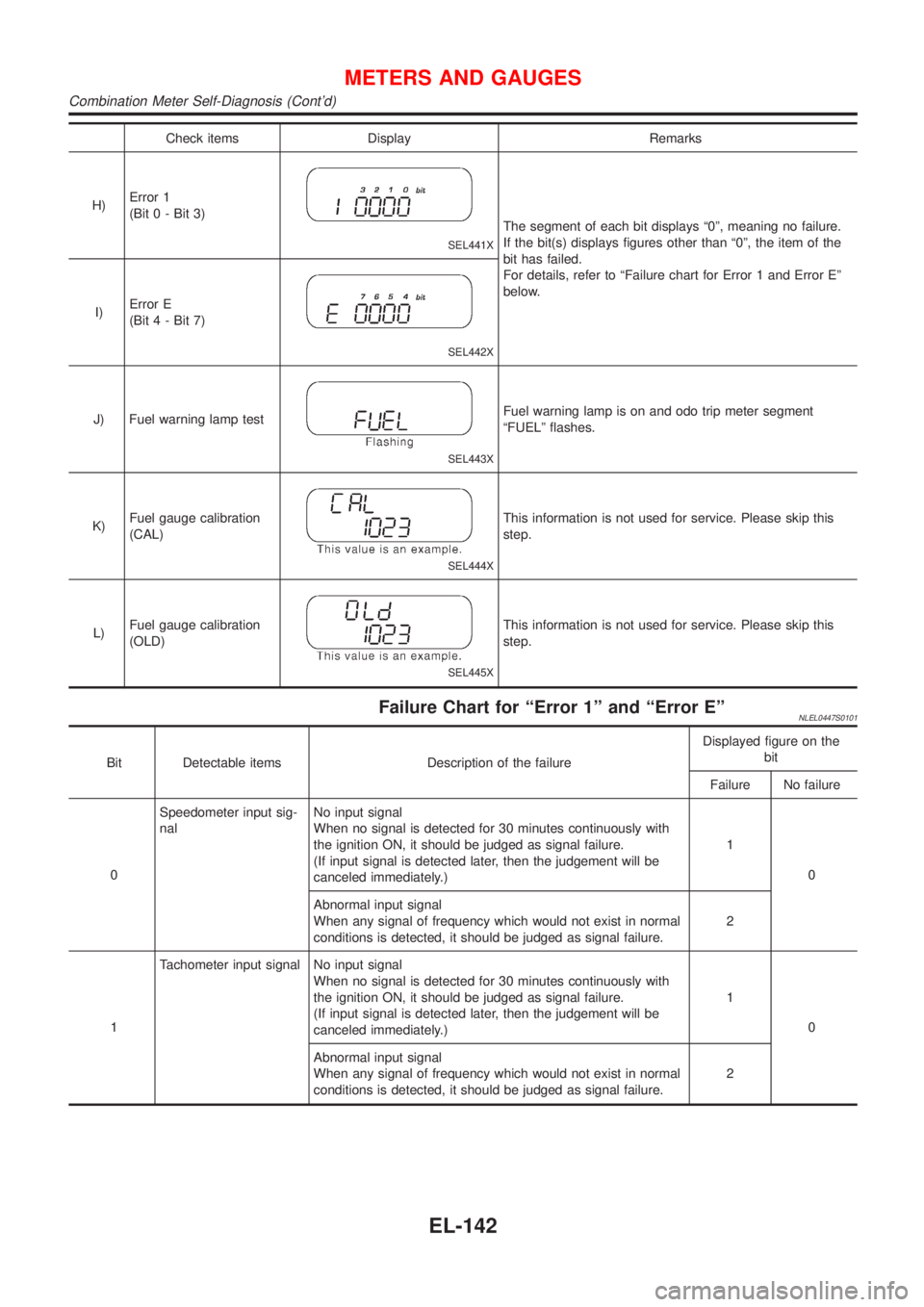
H)Error 1
(Bit 0 - Bit 3)
SEL441X
The segment of each bit displays ª0º, meaning no failure.
If the bit(s) displays figures other than ª0º, the item of the
bit has failed.
For details, refer to ªFailure chart for Error 1 and Error Eº
below.
I)Error E
(Bit 4 - Bit 7)
SEL442X
J) Fuel warning lamp test
SEL443X
Fuel warning lamp is on and odo trip meter segment
ªFUELº flashes.
K)Fuel gauge calibration
(CAL)
SEL444X
This information is not used for service. Please skip this
step.
L)Fuel gauge calibration
(OLD)
SEL445X
This information is not used for service. Please skip this
step.
Failure Chart for ªError 1º and ªError EºNLEL0447S0101
Bit Detectable items Description of the failureDisplayed figure on the
bit
Failure No failure
0Speedometer input sig-
nalNo input signal
When no signal is detected for 30 minutes continuously with
the ignition ON, it should be judged as signal failure.
(If input signal is detected later, then the judgement will be
canceled immediately.)1
0
Abnormal input signal
When any signal of frequency which would not exist in normal
conditions is detected, it should be judged as signal failure.2
1Tachometer input signal No input signal
When no signal is detected for 30 minutes continuously with
the ignition ON, it should be judged as signal failure.
(If input signal is detected later, then the judgement will be
canceled immediately.)1
0
Abnormal input signal
When any signal of frequency which would not exist in normal
conditions is detected, it should be judged as signal failure.2
METERS AND GAUGES
Combination Meter Self-Diagnosis (Cont'd)
EL-142
Page 1939 of 3051
System Description=NLEL0497Refer to Owner's Manual for audio system operating instructions.
Power is supplied at all times
+through 15A fuse
+to audio unit terminal 9
+to CD auto changer terminal 32.
With the ignition switch in the ACC or ON position, power is supplied
+through 10A fuse [No. 1, located in the fuse block (J/B)]
+to audio unit terminal 3,
+to CD auto changer terminal 36 and
Ground is supplied through the case of the audio unit.
Audio signals are supplied
+through audio unit terminals 7, 10, 11, 12, 13, 14, 15, 16
+to terminals 1 and 2 of front door speaker LH and RH,
+to terminals 1 and 2 of rear door speaker LH and RH and
+to terminals 1 and 2 of pillar tweeter LH and RH (with 6 speakers)
When the navigation system is triggered,
power is supplied
+through navi control unit terminal 46
+to speaker relay terminal 2
Ground is supplied
+through navi control unit terminal 44
+to speaker relay terminal 1
With power and ground supplied, the relay is energized, and then audio signal is interrupted to front door
speaker RH (LHD models) or LH (RHD models), and pillar tweeter RH (LHD models) or LH (RHD models)
For detailed, refer to ªNAVIGATION SYSTEMº.
NATS AUDIO LINKNLEL0497S01DescriptionNLEL0497S0101The link with the NATS IMMU implies that the audio unit can basically only be operated if connected to the
matching NATS IMMU to which the audio unit was initially fitted on the production line.
Since radio operation is impossible after the link with the NATS is disrupted theft of the audio unit is basically
useless since special equipment is required to reset the audio unit.
Initialization process for audio units that are linked to the NATS IMMU
New audio units will be delivered to the factories in the ªNEWº state, i.e. ready to be linked with the vehicle's
NATS. When the audio unit in ªNEWº state is first switched on at the factory, it will start up communication
with the vehicle's immobiliser control unit (IMMU) and send a code (the ªaudio unit Codeº) to the IMMU. The
IMMU will then store this code, which is unique to each audio unit, in its (permanent) memory.
Upon receipt of the code by the IMMU, the NATS will confirm correct receipt of the audio unit code to the audio
unit. Hereafter, the audio unit will operate as normal.
During the initialisation process, ªNEWº is displayed on the audio unit display. Normally though, communica-
tion between audio unit and IMMU takes such a short time (300 ms) that the audio unit seems to switch on
directly without showing ªNEWº on its display.
Normal operation
Each time the audio unit is switched on afterwards, the audio unit code will be verified between the audio unit
and the NATS before the audio unit becomes operational. During the code verification process, ªWAITº is
shown on the audio unit display. Again, the communication takes such a short time (300 ms) that the audio
unit seems to switch on directly without showing ªWAITº on its display.
When the radio is locked
In case of a audio unit being linked with the vehicle's NATS (immobilizer system), disconnection of the link
between the audio unit and the IMMU will cause the audio unit to switch into the lock (ªSECUREº) mode in
which the audio unit is fully inoperative. Hence, repair of the audio unit is basically impossible, unless the audio
unit is reset to the ªNEWº state for which special decoding equipment is required.
Clarion has provided their authorized service representatives with so called ªdecoder boxesº which can bring
the audio unit back to the ªNEWº state, enabling the audio unit to be switched on after which repair can be
AUDIO
System Description
EL-208
Page 1940 of 3051
carried out. Subsequently, when the repaired audio unit is delivered to the final user again, it will be in the
ªNEWº state as to enable re-linking the audio unit to the vehicle's immobiliser system. As a result of the above,
repair of the audio unit can only be done by an authorized Clarion representative.
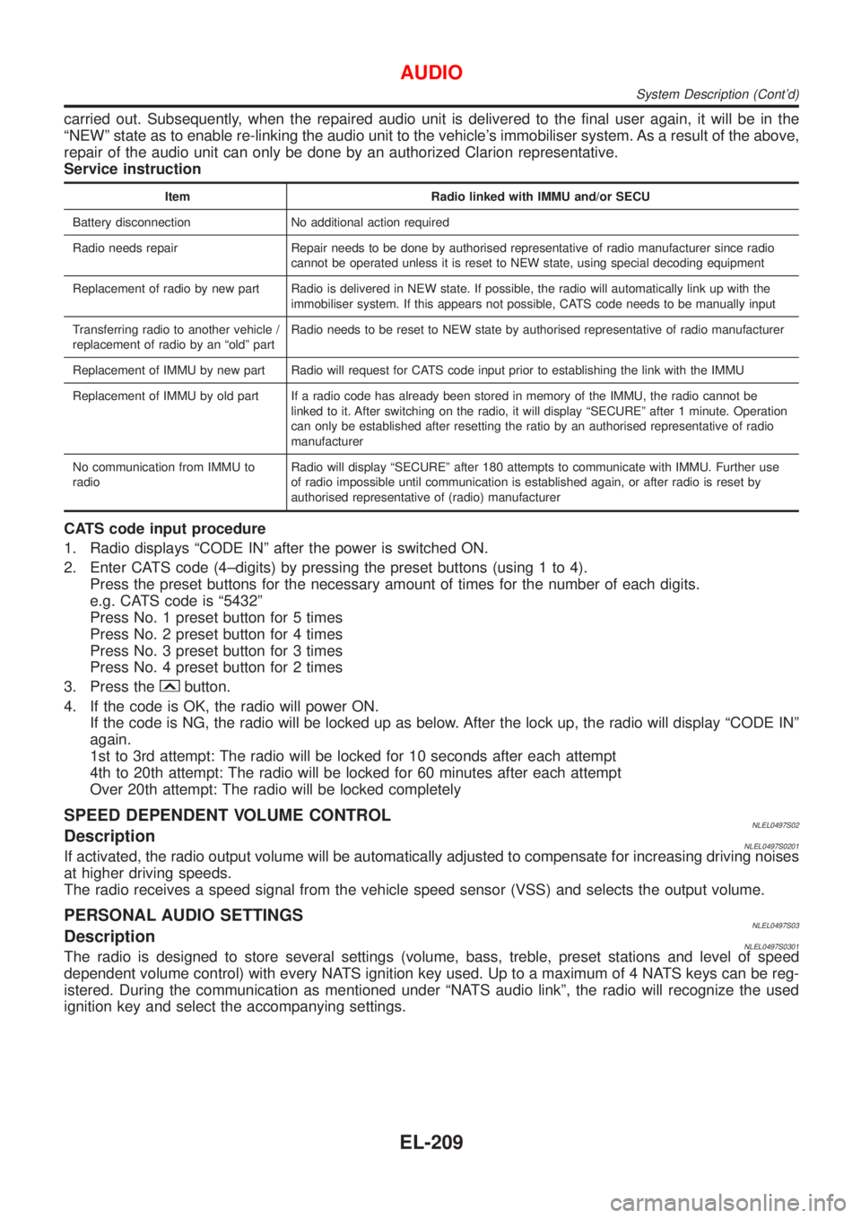
Service instruction
Item Radio linked with IMMU and/or SECU
Battery disconnection No additional action required
Radio needs repair Repair needs to be done by authorised representative of radio manufacturer since radio
cannot be operated unless it is reset to NEW state, using special decoding equipment
Replacement of radio by new part Radio is delivered in NEW state. If possible, the radio will automatically link up with the
immobiliser system. If this appears not possible, CATS code needs to be manually input
Transferring radio to another vehicle /
replacement of radio by an ªoldº partRadio needs to be reset to NEW state by authorised representative of radio manufacturer
Replacement of IMMU by new part Radio will request for CATS code input prior to establishing the link with the IMMU
Replacement of IMMU by old part If a radio code has already been stored in memory of the IMMU, the radio cannot be
linked to it. After switching on the radio, it will display ªSECUREº after 1 minute. Operation
can only be established after resetting the ratio by an authorised representative of radio
manufacturer
No communication from IMMU to
radioRadio will display ªSECUREº after 180 attempts to communicate with IMMU. Further use
of radio impossible until communication is established again, or after radio is reset by
authorised representative of (radio) manufacturer
CATS code input procedure
1. Radio displays ªCODE INº after the power is switched ON.
2. Enter CATS code (4±digits) by pressing the preset buttons (using 1 to 4).
Press the preset buttons for the necessary amount of times for the number of each digits.
e.g. CATS code is ª5432º
Press No. 1 preset button for 5 times
Press No. 2 preset button for 4 times
Press No. 3 preset button for 3 times
Press No. 4 preset button for 2 times
3. Press the
button.
4. If the code is OK, the radio will power ON.
If the code is NG, the radio will be locked up as below. After the lock up, the radio will display ªCODE INº
again.
1st to 3rd attempt: The radio will be locked for 10 seconds after each attempt
4th to 20th attempt: The radio will be locked for 60 minutes after each attempt
Over 20th attempt: The radio will be locked completely
SPEED DEPENDENT VOLUME CONTROLNLEL0497S02DescriptionNLEL0497S0201If activated, the radio output volume will be automatically adjusted to compensate for increasing driving noises
at higher driving speeds.
The radio receives a speed signal from the vehicle speed sensor (VSS) and selects the output volume.
PERSONAL AUDIO SETTINGSNLEL0497S03DescriptionNLEL0497S0301The radio is designed to store several settings (volume, bass, treble, preset stations and level of speed
dependent volume control) with every NATS ignition key used. Up to a maximum of 4 NATS keys can be reg-
istered. During the communication as mentioned under ªNATS audio linkº, the radio will recognize the used
ignition key and select the accompanying settings.
AUDIO
System Description (Cont'd)
EL-209
Page 2050 of 3051
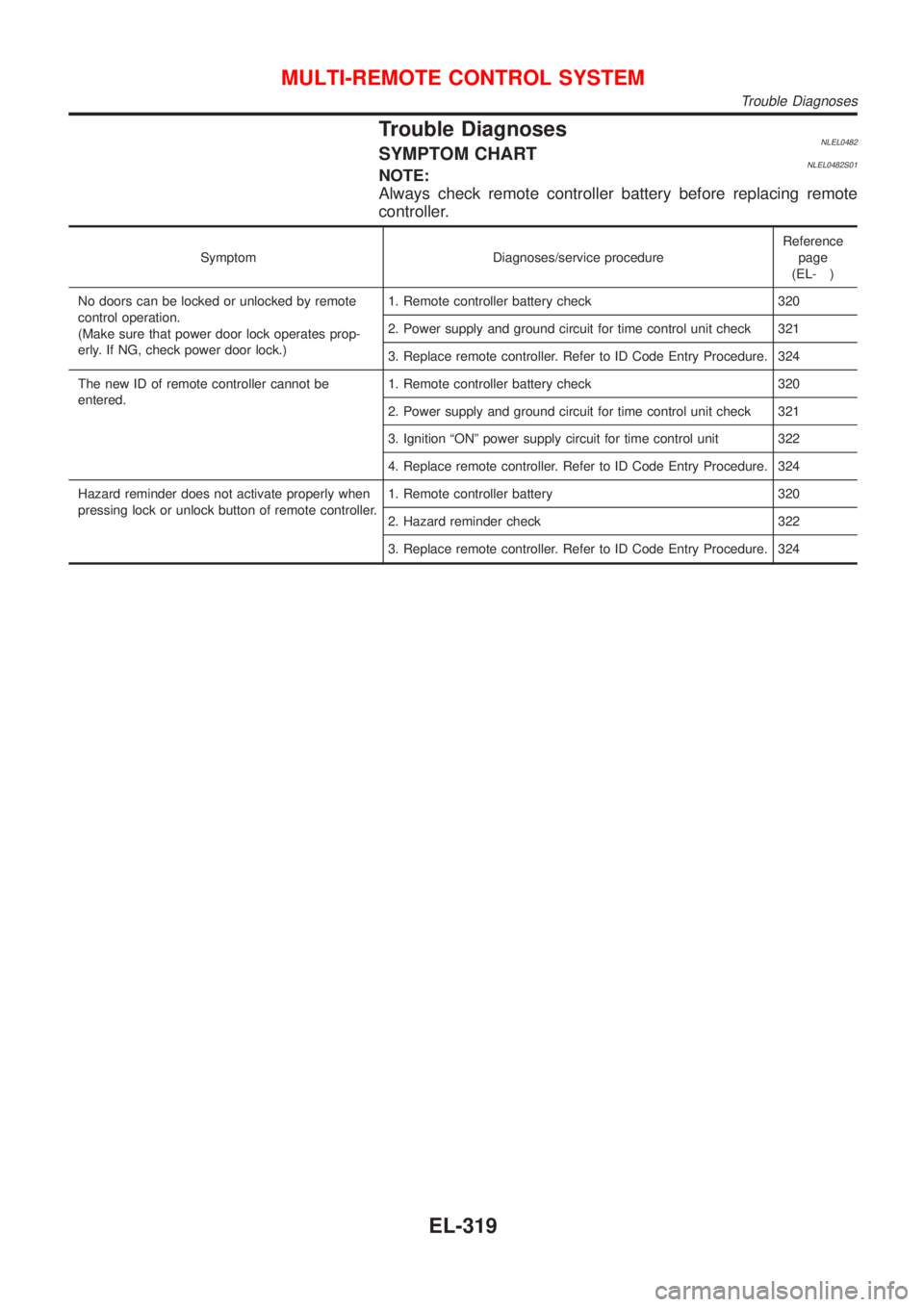
Trouble DiagnosesNLEL0482SYMPTOM CHARTNLEL0482S01NOTE:
Always check remote controller battery before replacing remote
controller.
Symptom Diagnoses/service procedureReference
page
(EL- )
No doors can be locked or unlocked by remote
control operation.
(Make sure that power door lock operates prop-
erly. If NG, check power door lock.)1. Remote controller battery check 320
2. Power supply and ground circuit for time control unit check 321
3. Replace remote controller. Refer to ID Code Entry Procedure. 324
The new ID of remote controller cannot be
entered.1. Remote controller battery check 320
2. Power supply and ground circuit for time control unit check 321
3. Ignition ªONº power supply circuit for time control unit 322
4. Replace remote controller. Refer to ID Code Entry Procedure. 324
Hazard reminder does not activate properly when
pressing lock or unlock button of remote controller.1. Remote controller battery 320
2. Hazard reminder check 322
3. Replace remote controller. Refer to ID Code Entry Procedure. 324
MULTI-REMOTE CONTROL SYSTEM
Trouble Diagnoses
EL-319
Page 2058 of 3051
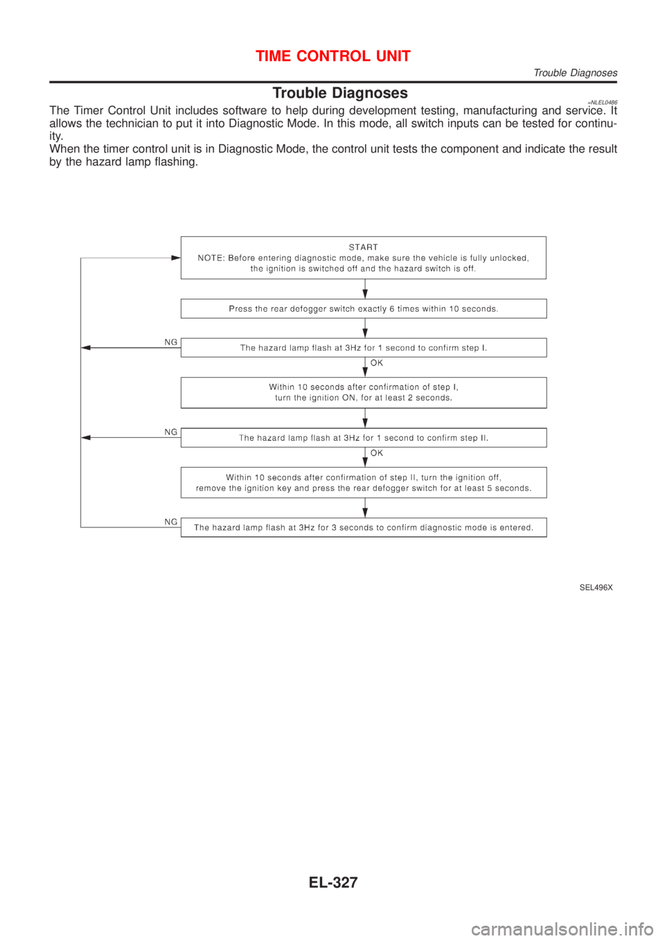
Trouble Diagnoses=NLEL0486The Timer Control Unit includes software to help during development testing, manufacturing and service. It
allows the technician to put it into Diagnostic Mode. In this mode, all switch inputs can be tested for continu-
ity.
When the timer control unit is in Diagnostic Mode, the control unit tests the component and indicate the result
by the hazard lamp flashing.
SEL496X
TIME CONTROL UNIT
Trouble Diagnoses
EL-327
Page 2077 of 3051
SEF094Y
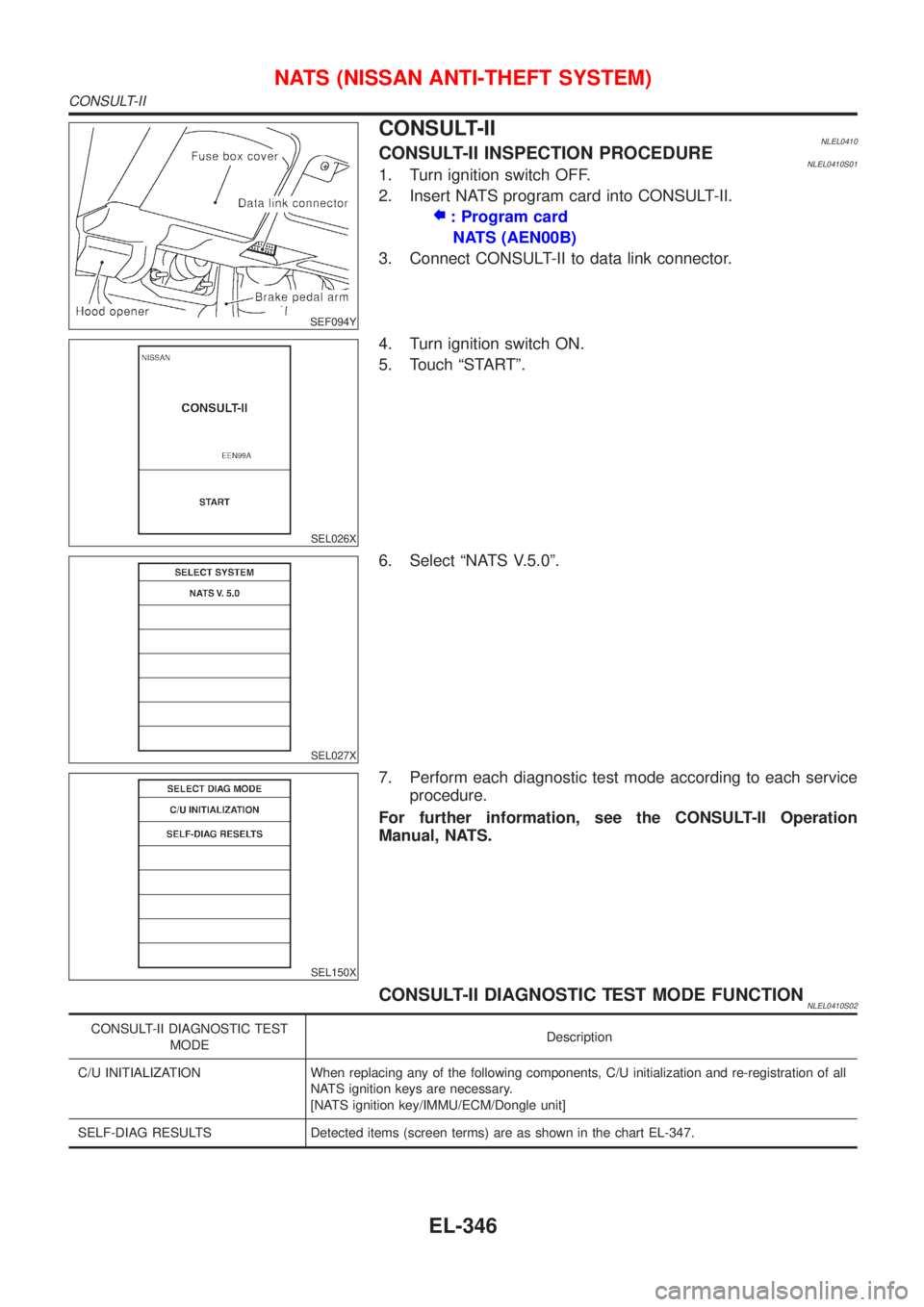
CONSULT-IINLEL0410CONSULT-II INSPECTION PROCEDURENLEL0410S011. Turn ignition switch OFF.
2. Insert NATS program card into CONSULT-II.
: Program card
NATS (AEN00B)
3. Connect CONSULT-II to data link connector.
SEL026X
4. Turn ignition switch ON.
5. Touch ªSTARTº.
SEL027X
6. Select ªNATS V.5.0º.
SEL150X
7. Perform each diagnostic test mode according to each service
procedure.
For further information, see the CONSULT-II Operation
Manual, NATS.
CONSULT-II DIAGNOSTIC TEST MODE FUNCTIONNLEL0410S02
CONSULT-II DIAGNOSTIC TEST
MODEDescription
C/U INITIALIZATION When replacing any of the following components, C/U initialization and re-registration of all
NATS ignition keys are necessary.
[NATS ignition key/IMMU/ECM/Dongle unit]
SELF-DIAG RESULTS Detected items (screen terms) are as shown in the chart EL-347.
NATS (NISSAN ANTI-THEFT SYSTEM)
CONSULT-II
EL-346