2001 NISSAN ALMERA TINO service
[x] Cancel search: servicePage 1006 of 3051
SEF217Z
SEF454Y
SEF455Y
Idle Air Volume LearningNLEC1358DESCRIPTIONNLEC1358S01ªIdle Air Volume Learningº is an operation to learn the idle air vol-
ume that keeps each engine within the specific range. It must be
performed under any of the following conditions:
+Each time IACV-AAC valve, throttle body or ECM is replaced.
+Idle speed or ignition timing is out of specification.
PRE-CONDITIONINGNLEC1358S02Before performing ªIdle Air Volume Learningº, make sure that all of
the following conditions are satisfied.
Learning will be cancelled if any of the following conditions are
missed for even a moment.
+Battery voltage: More than 12.9V (At idle)
+Engine coolant temperature: 70 - 95ÉC (158 - 203ÉF)
+PNP switch: ON
+Electric load switch: OFF
(Air conditioner, headlamp, rear window defogger)
On vehicles equipped with daytime light systems, set lighting
switch to the 1st position to light only small lamps.
+Cooling fan motor: Not operating
+Steering wheel: Neutral (Straight-ahead position)
+Vehicle speed: Stopped
+Transmission: Warmed-up
For models with CONSULT-II, drive vehicle until ªFLUID TEMP
SEº in ªDATA MONITORº mode of ªCVTº indicates less than
0.9V.
For models without CONSULT-II, drive vehicle for 10 minutes.
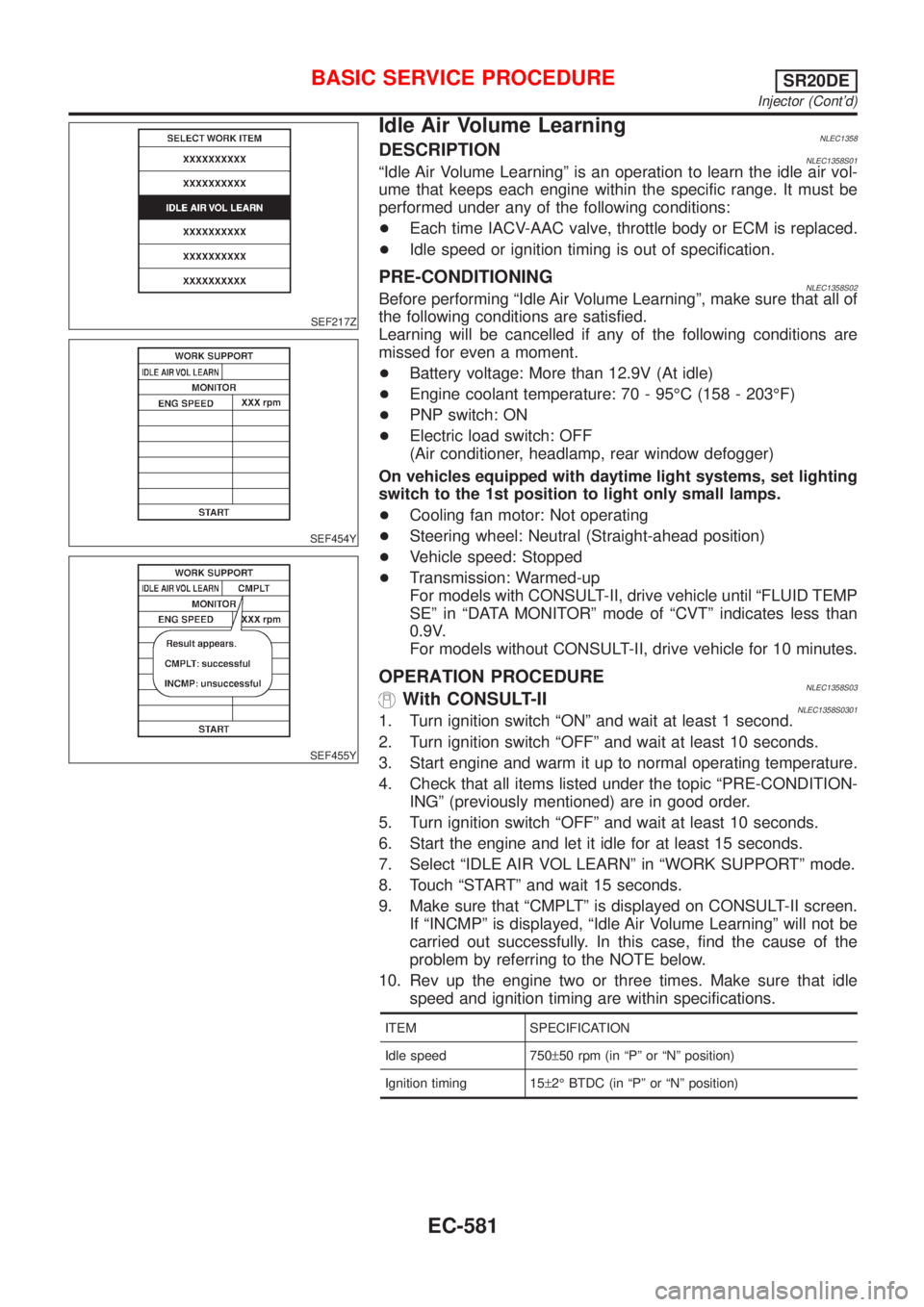
OPERATION PROCEDURENLEC1358S03With CONSULT-IINLEC1358S03011. Turn ignition switch ªONº and wait at least 1 second.
2. Turn ignition switch ªOFFº and wait at least 10 seconds.
3. Start engine and warm it up to normal operating temperature.
4. Check that all items listed under the topic ªPRE-CONDITION-
INGº (previously mentioned) are in good order.
5. Turn ignition switch ªOFFº and wait at least 10 seconds.
6. Start the engine and let it idle for at least 15 seconds.
7. Select ªIDLE AIR VOL LEARNº in ªWORK SUPPORTº mode.
8. Touch ªSTARTº and wait 15 seconds.
9. Make sure that ªCMPLTº is displayed on CONSULT-II screen.
If ªINCMPº is displayed, ªIdle Air Volume Learningº will not be
carried out successfully. In this case, find the cause of the
problem by referring to the NOTE below.
10. Rev up the engine two or three times. Make sure that idle
speed and ignition timing are within specifications.
ITEM SPECIFICATION
Idle speed 750±50 rpm (in ªPº or ªNº position)
Ignition timing 15±2É BTDC (in ªPº or ªNº position)
BASIC SERVICE PROCEDURESR20DE
Injector (Cont'd)
EC-581
Page 1007 of 3051
SEF770Z
Without CONSULT-IINLEC1358S03021. Turn ignition switch ªONº and wait at least 1 second.
2. Turn ignition switch ªOFFº and wait at least 10 seconds.
3. Start engine and warm it up to normal operating temperature.
4. Check that all items listed under the topic ªPRE-CONDITION-
INGº (previously mentioned) are in good order.
5. Turn ignition switch ªOFFº and wait at least 10 seconds.
6. Start the engine and let it idle for at least 15 seconds.
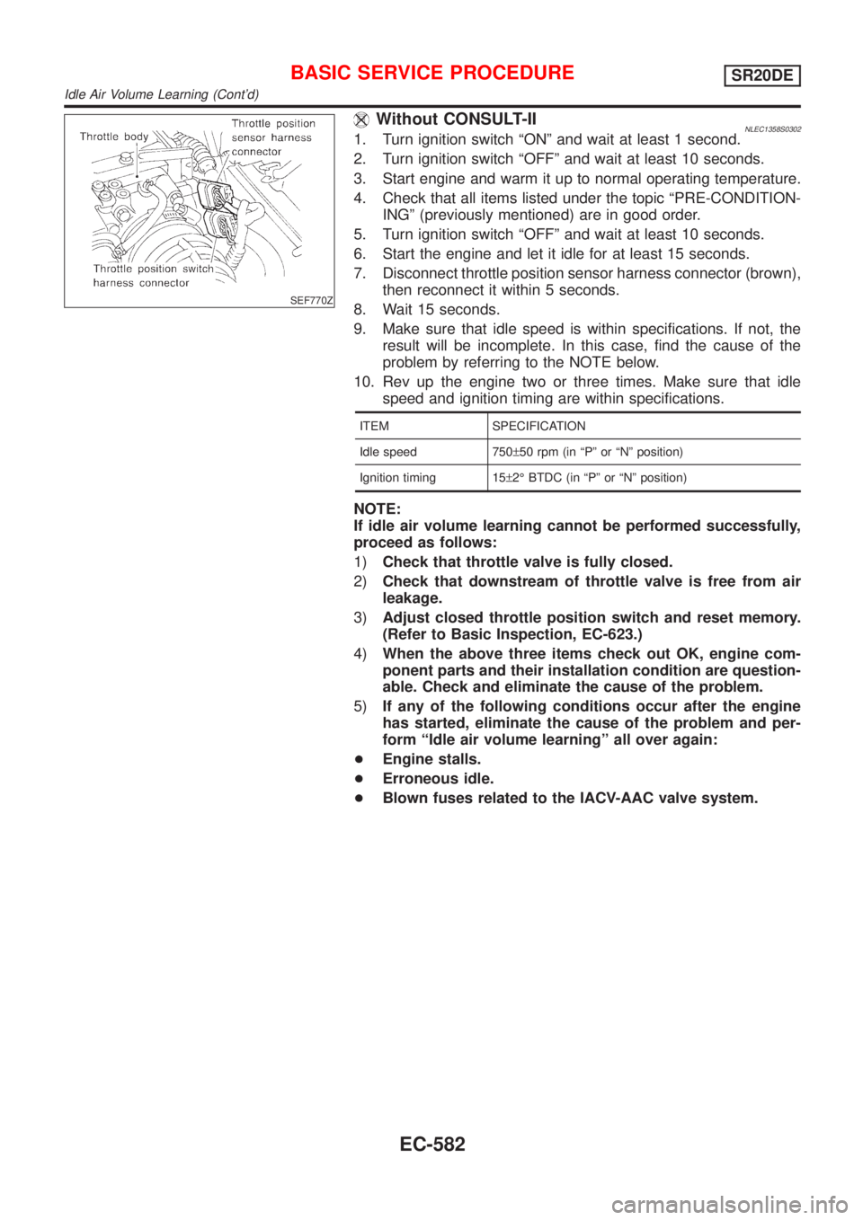
7. Disconnect throttle position sensor harness connector (brown),
then reconnect it within 5 seconds.
8. Wait 15 seconds.
9. Make sure that idle speed is within specifications. If not, the
result will be incomplete. In this case, find the cause of the
problem by referring to the NOTE below.
10. Rev up the engine two or three times. Make sure that idle
speed and ignition timing are within specifications.
ITEM SPECIFICATION
Idle speed 750±50 rpm (in ªPº or ªNº position)
Ignition timing 15±2É BTDC (in ªPº or ªNº position)
NOTE:
If idle air volume learning cannot be performed successfully,
proceed as follows:
1)Check that throttle valve is fully closed.
2)Check that downstream of throttle valve is free from air
leakage.
3)Adjust closed throttle position switch and reset memory.
(Refer to Basic Inspection, EC-623.)
4)When the above three items check out OK, engine com-
ponent parts and their installation condition are question-
able. Check and eliminate the cause of the problem.
5)If any of the following conditions occur after the engine
has started, eliminate the cause of the problem and per-
form ªIdle air volume learningº all over again:
+Engine stalls.
+Erroneous idle.
+Blown fuses related to the IACV-AAC valve system.
BASIC SERVICE PROCEDURESR20DE
Idle Air Volume Learning (Cont'd)
EC-582
Page 1011 of 3051
System Readiness Test (SRT) CodeNLEC1361S0103System Readiness Test (SRT) code is specified in Mode 1 of ISO 15031-5.
As part of an emissions test for Inspection & Maintenance (I/M), certain states require the status of SRT be
used to indicate whether the ECM has completed self-diagnosis of major emission systems and components.
Completion must be verified in order for the emissions inspection to proceed.
If a vehicle is rejected for a State emissions inspection due to one or more SRT items indicating ªINCMPº,
use the information in this Service Manual to set the SRT to ªCMPLTº.
In most cases the ECM will automatically complete its self-diagnosis cycle during normal usage, and the SRT
status will indicate ªCMPLTº for each application system. Once set as ªCMPLTº, the SRT status remains
ªCMPLTº until the self-diagnosis memory is erased.
Occasionally, certain portions of the self-diagnostic test may not be completed as a result of the customer's
normal driving pattern; the SRT will indicate ªINCMPº for these items.
NOTE:
The SRT will also indicate ªINCMPº if the self-diagnosis memory is erased for any reason or if the ECM
memory power supply is interrupted for several hours.
If, during the state emissions inspection, the SRT indicates ªCMPLTº for all test items, the inspector will con-
tinue with the emissions test. However, if the SRT indicates ªINCMPº for one or more of the SRT items the
vehicle is returned to the customer untested.
NOTE:
If MI is ªONº during the state emissions inspection, the vehicle is also returned to the customer untested even
though the SRT indicates ªCMPLTº for all test items. Therefore, it is important to check SRT (ªCMPLTº) and
DTC (No DTCs) before the inspection.
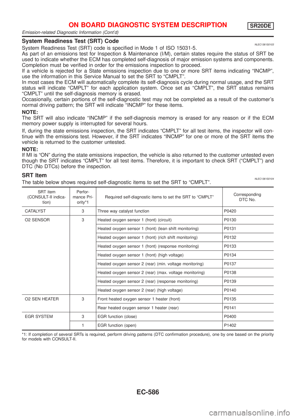
SRT ItemNLEC1361S0104The table below shows required self-diagnostic items to set the SRT to ªCMPLTº.
SRT item
(CONSULT-II indica-
tion)Perfor-
mance Pri-
ority*1Required self-diagnostic items to set the SRT to ªCMPLTºCorresponding
DTC No.
CATALYST 3 Three way catalyst function P0420
O2 SENSOR 3 Heated oxygen sensor 1 (front) (circuit) P0130
Heated oxygen sensor 1 (front) (lean shift monitoring) P0131
Heated oxygen sensor 1 (front) (rich shift monitoring) P0132
Heated oxygen sensor 1 (front) (response monitoring) P0133
Heated oxygen sensor 1 (front) (high voltage) P0134
Heated oxygen sensor 2 (rear) (min. voltage monitoring) P0137
Heated oxygen sensor 2 (rear) (max. voltage monitoring) P0138
Heated oxygen sensor 2 (rear) (response monitoring) P0139
Heated oxygen sensor 2 (rear) (high voltage) P0140
O2 SEN HEATER 3 Front heated oxygen sensor 1 heater (front) P0135
Rear heated oxygen sensor 1 heater (rear) P0141
EGR SYSTEM 3 EGR function (close) P0400
1 EGR function (open) P1402
*1: If completion of several SRTs is required, perform driving patterns (DTC confirmation procedure), one by one based on the priority
for models with CONSULT-II.
ON BOARD DIAGNOSTIC SYSTEM DESCRIPTIONSR20DE
Emission-related Diagnostic Information (Cont'd)
EC-586
Page 1012 of 3051
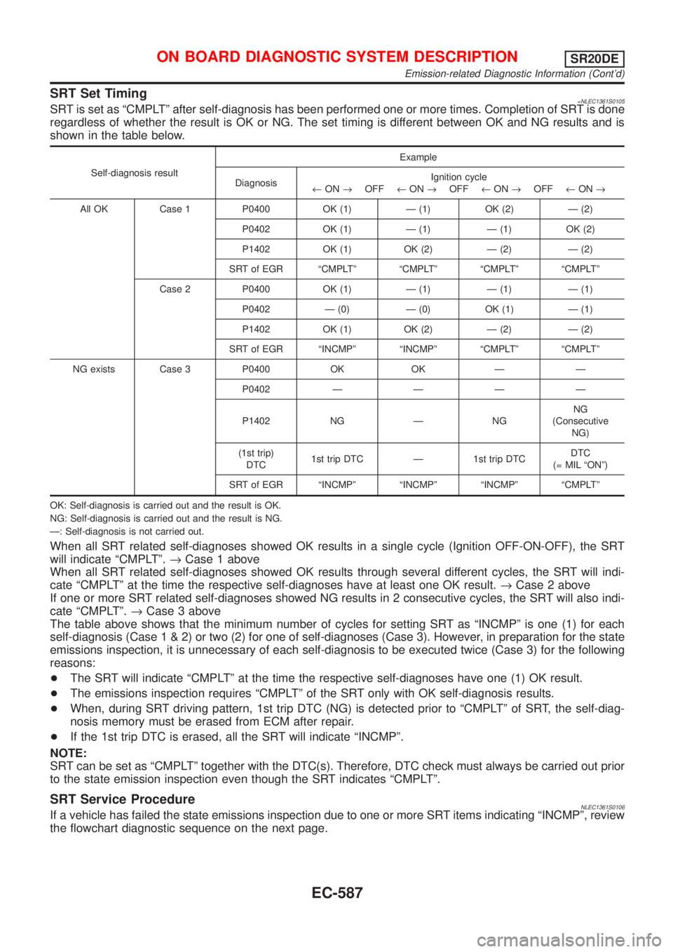
SRT Set Timing=NLEC1361S0105SRT is set as ªCMPLTº after self-diagnosis has been performed one or more times. Completion of SRT is done
regardless of whether the result is OK or NG. The set timing is different between OK and NG results and is
shown in the table below.
Self-diagnosis resultExample
DiagnosisIgnition cycle
¬ON®OFF¬ON®OFF¬ON®OFF¬ON®
All OK Case 1 P0400 OK (1) Ð (1) OK (2) Ð (2)
P0402 OK (1) Ð (1) Ð (1) OK (2)
P1402 OK (1) OK (2) Ð (2) Ð (2)
SRT of EGR ªCMPLTº ªCMPLTº ªCMPLTº ªCMPLTº
Case 2 P0400 OK (1) Ð (1) Ð (1) Ð (1)
P0402 Ð (0) Ð (0) OK (1) Ð (1)
P1402 OK (1) OK (2) Ð (2) Ð (2)
SRT of EGR ªINCMPº ªINCMPº ªCMPLTº ªCMPLTº
NG exists Case 3 P0400 OK OK Ð Ð
P0402ÐÐÐÐ
P1402 NG Ð NGNG
(Consecutive
NG)
(1st trip)
DTC1st trip DTC Ð 1st trip DTCDTC
(= MIL ªONº)
SRT of EGR ªINCMPº ªINCMPº ªINCMPº ªCMPLTº
OK: Self-diagnosis is carried out and the result is OK.
NG: Self-diagnosis is carried out and the result is NG.
Ð: Self-diagnosis is not carried out.
When all SRT related self-diagnoses showed OK results in a single cycle (Ignition OFF-ON-OFF), the SRT
will indicate ªCMPLTº.®Case 1 above
When all SRT related self-diagnoses showed OK results through several different cycles, the SRT will indi-
cate ªCMPLTº at the time the respective self-diagnoses have at least one OK result.®Case 2 above
If one or more SRT related self-diagnoses showed NG results in 2 consecutive cycles, the SRT will also indi-
cate ªCMPLTº.®Case 3 above
The table above shows that the minimum number of cycles for setting SRT as ªINCMPº is one (1) for each
self-diagnosis (Case1&2)ortwo(2)foroneofself-diagnoses (Case 3). However, in preparation for the state
emissions inspection, it is unnecessary of each self-diagnosis to be executed twice (Case 3) for the following
reasons:
+The SRT will indicate ªCMPLTº at the time the respective self-diagnoses have one (1) OK result.
+The emissions inspection requires ªCMPLTº of the SRT only with OK self-diagnosis results.
+When, during SRT driving pattern, 1st trip DTC (NG) is detected prior to ªCMPLTº of SRT, the self-diag-
nosis memory must be erased from ECM after repair.
+If the 1st trip DTC is erased, all the SRT will indicate ªINCMPº.
NOTE:
SRT can be set as ªCMPLTº together with the DTC(s). Therefore, DTC check must always be carried out prior
to the state emission inspection even though the SRT indicates ªCMPLTº.
SRT Service ProcedureNLEC1361S0106If a vehicle has failed the state emissions inspection due to one or more SRT items indicating ªINCMPº, review
the flowchart diagnostic sequence on the next page.
ON BOARD DIAGNOSTIC SYSTEM DESCRIPTIONSR20DE
Emission-related Diagnostic Information (Cont'd)
EC-587
Page 1032 of 3051
SEF094Y
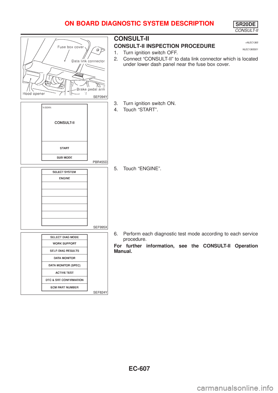
CONSULT-II=NLEC1365CONSULT-II INSPECTION PROCEDURENLEC1365S011. Turn ignition switch OFF.
2. Connect ªCONSULT-IIº to data link connector which is located
under lower dash panel near the fuse box cover.
PBR455D
3. Turn ignition switch ON.
4. Touch ªSTARTº.
SEF995X
5. Touch ªENGINEº.
SEF824Y
6. Perform each diagnostic test mode according to each service
procedure.
For further information, see the CONSULT-II Operation
Manual.
ON BOARD DIAGNOSTIC SYSTEM DESCRIPTIONSR20DE
CONSULT-II
EC-607
Page 1035 of 3051
7) Distance traveled while MI is activated.
8) Others
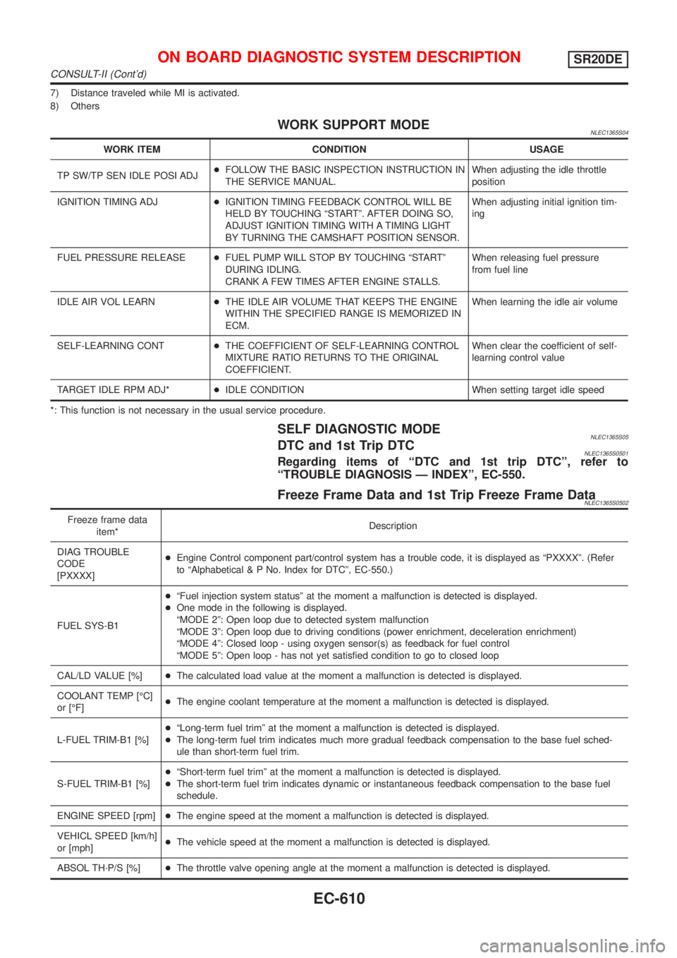
WORK SUPPORT MODENLEC1365S04
WORK ITEM CONDITION USAGE
TP SW/TP SEN IDLE POSI ADJ+FOLLOW THE BASIC INSPECTION INSTRUCTION IN
THE SERVICE MANUAL.When adjusting the idle throttle
position
IGNITION TIMING ADJ+IGNITION TIMING FEEDBACK CONTROL WILL BE
HELD BY TOUCHING ªSTARTº. AFTER DOING SO,
ADJUST IGNITION TIMING WITH A TIMING LIGHT
BY TURNING THE CAMSHAFT POSITION SENSOR.When adjusting initial ignition tim-
ing
FUEL PRESSURE RELEASE+FUEL PUMP WILL STOP BY TOUCHING ªSTARTº
DURING IDLING.
CRANK A FEW TIMES AFTER ENGINE STALLS.When releasing fuel pressure
from fuel line
IDLE AIR VOL LEARN+THE IDLE AIR VOLUME THAT KEEPS THE ENGINE
WITHIN THE SPECIFIED RANGE IS MEMORIZED IN
ECM.When learning the idle air volume
SELF-LEARNING CONT+THE COEFFICIENT OF SELF-LEARNING CONTROL
MIXTURE RATIO RETURNS TO THE ORIGINAL
COEFFICIENT.When clear the coefficient of self-
learning control value
TARGET IDLE RPM ADJ*+IDLE CONDITION When setting target idle speed
*: This function is not necessary in the usual service procedure.
SELF DIAGNOSTIC MODENLEC1365S05DTC and 1st Trip DTCNLEC1365S0501Regarding items of ªDTC and 1st trip DTCº, refer to
ªTROUBLE DIAGNOSIS Ð INDEXº, EC-550.
Freeze Frame Data and 1st Trip Freeze Frame DataNLEC1365S0502
Freeze frame data
item*Description
DIAG TROUBLE
CODE
[PXXXX]+Engine Control component part/control system has a trouble code, it is displayed as ªPXXXXº. (Refer
to ªAlphabetical & P No. Index for DTCº, EC-550.)
FUEL SYS-B1+ªFuel injection system statusº at the moment a malfunction is detected is displayed.
+One mode in the following is displayed.
ªMODE 2º: Open loop due to detected system malfunction
ªMODE 3º: Open loop due to driving conditions (power enrichment, deceleration enrichment)
ªMODE 4º: Closed loop - using oxygen sensor(s) as feedback for fuel control
ªMODE 5º: Open loop - has not yet satisfied condition to go to closed loop
CAL/LD VALUE [%]+The calculated load value at the moment a malfunction is detected is displayed.
COOLANT TEMP [ÉC]
or [ÉF]+The engine coolant temperature at the moment a malfunction is detected is displayed.
L-FUEL TRIM-B1 [%]+ªLong-term fuel trimº at the moment a malfunction is detected is displayed.
+The long-term fuel trim indicates much more gradual feedback compensation to the base fuel sched-
ule than short-term fuel trim.
S-FUEL TRIM-B1 [%]+ªShort-term fuel trimº at the moment a malfunction is detected is displayed.
+The short-term fuel trim indicates dynamic or instantaneous feedback compensation to the base fuel
schedule.
ENGINE SPEED [rpm]+The engine speed at the moment a malfunction is detected is displayed.
VEHICL SPEED [km/h]
or [mph]+The vehicle speed at the moment a malfunction is detected is displayed.
ABSOL TH´P/S [%]+The throttle valve opening angle at the moment a malfunction is detected is displayed.
ON BOARD DIAGNOSTIC SYSTEM DESCRIPTIONSR20DE
CONSULT-II (Cont'd)
EC-610
Page 1042 of 3051
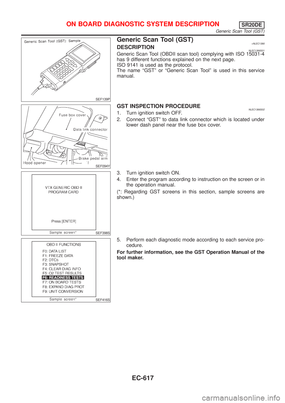
SEF139P
Generic Scan Tool (GST)=NLEC1366DESCRIPTIONNLEC1366S01Generic Scan Tool (OBDII scan tool) complying with ISO 15031-4
has 9 different functions explained on the next page.
ISO 9141 is used as the protocol.
The name ªGSTº or ªGeneric Scan Toolº is used in this service
manual.
SEF094Y
GST INSPECTION PROCEDURENLEC1366S021. Turn ignition switch OFF.
2. Connect ªGSTº to data link connector which is located under
lower dash panel near the fuse box cover.
SEF398S
3. Turn ignition switch ON.
4. Enter the program according to instruction on the screen or in
the operation manual.
(*: Regarding GST screens in this section, sample screens are
shown.)
SEF416S
5. Perform each diagnostic mode according to each service pro-
cedure.
For further information, see the GST Operation Manual of the
tool maker.
ON BOARD DIAGNOSTIC SYSTEM DESCRIPTIONSR20DE
Generic Scan Tool (GST)
EC-617
Page 1047 of 3051
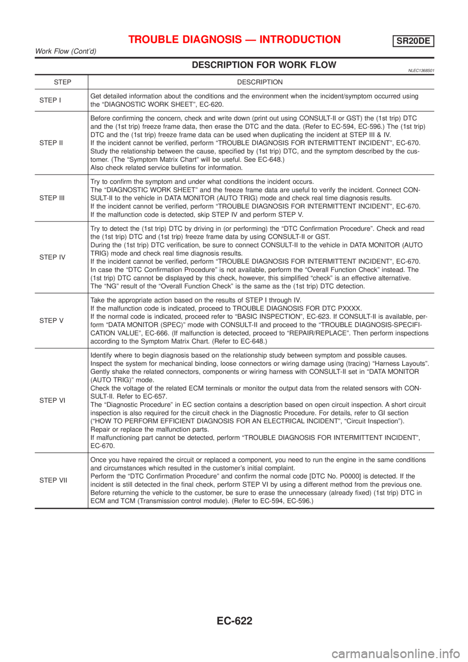
DESCRIPTION FOR WORK FLOWNLEC1368S01
STEP DESCRIPTION
STEP IGet detailed information about the conditions and the environment when the incident/symptom occurred using
the ªDIAGNOSTIC WORK SHEETº, EC-620.
STEP IIBefore confirming the concern, check and write down (print out using CONSULT-II or GST) the (1st trip) DTC
and the (1st trip) freeze frame data, then erase the DTC and the data. (Refer to EC-594, EC-596.) The (1st trip)
DTC and the (1st trip) freeze frame data can be used when duplicating the incident at STEP III & IV.
If the incident cannot be verified, perform ªTROUBLE DIAGNOSIS FOR INTERMITTENT INCIDENTº, EC-670.
Study the relationship between the cause, specified by (1st trip) DTC, and the symptom described by the cus-
tomer. (The ªSymptom Matrix Chartº will be useful. See EC-648.)
Also check related service bulletins for information.
STEP IIITry to confirm the symptom and under what conditions the incident occurs.
The ªDIAGNOSTIC WORK SHEETº and the freeze frame data are useful to verify the incident. Connect CON-
SULT-II to the vehicle in DATA MONITOR (AUTO TRIG) mode and check real time diagnosis results.
If the incident cannot be verified, perform ªTROUBLE DIAGNOSIS FOR INTERMITTENT INCIDENTº, EC-670.
If the malfunction code is detected, skip STEP IV and perform STEP V.
STEP IVTry to detect the (1st trip) DTC by driving in (or performing) the ªDTC Confirmation Procedureº. Check and read
the (1st trip) DTC and (1st trip) freeze frame data by using CONSULT-II or GST.
During the (1st trip) DTC verification, be sure to connect CONSULT-II to the vehicle in DATA MONITOR (AUTO
TRIG) mode and check real time diagnosis results.
If the incident cannot be verified, perform ªTROUBLE DIAGNOSIS FOR INTERMITTENT INCIDENTº, EC-670.
In case the ªDTC Confirmation Procedureº is not available, perform the ªOverall Function Checkº instead. The
(1st trip) DTC cannot be displayed by this check, however, this simplified ªcheckº is an effective alternative.
The ªNGº result of the ªOverall Function Checkº is the same as the (1st trip) DTC detection.
STEP VTake the appropriate action based on the results of STEP I through IV.
If the malfunction code is indicated, proceed to TROUBLE DIAGNOSIS FOR DTC PXXXX.
If the normal code is indicated, proceed refer to ªBASIC INSPECTIONº, EC-623. If CONSULT-II is available, per-
form ªDATA MONITOR (SPEC)º mode with CONSULT-II and proceed to the ªTROUBLE DIAGNOSIS-SPECIFI-
CATION VALUEº, EC-666. (If malfunction is detected, proceed to ªREPAIR/REPLACEº. Then perform inspections
according to the Symptom Matrix Chart. (Refer to EC-648.)
STEP VIIdentify where to begin diagnosis based on the relationship study between symptom and possible causes.
Inspect the system for mechanical binding, loose connectors or wiring damage using (tracing) ªHarness Layoutsº.
Gently shake the related connectors, components or wiring harness with CONSULT-II set in ªDATA MONITOR
(AUTO TRIG)º mode.
Check the voltage of the related ECM terminals or monitor the output data from the related sensors with CON-
SULT-II. Refer to EC-657.
The ªDiagnostic Procedureº in EC section contains a description based on open circuit inspection. A short circuit
inspection is also required for the circuit check in the Diagnostic Procedure. For details, refer to GI section
(ªHOW TO PERFORM EFFICIENT DIAGNOSIS FOR AN ELECTRICAL INCIDENTº, ªCircuit Inspectionº).
Repair or replace the malfunction parts.
If malfunctioning part cannot be detected, perform ªTROUBLE DIAGNOSIS FOR INTERMITTENT INCIDENTº,
EC-670.
STEP VIIOnce you have repaired the circuit or replaced a component, you need to run the engine in the same conditions
and circumstances which resulted in the customer's initial complaint.
Perform the ªDTC Confirmation Procedureº and confirm the normal code [DTC No. P0000] is detected. If the
incident is still detected in the final check, perform STEP VI by using a different method from the previous one.
Before returning the vehicle to the customer, be sure to erase the unnecessary (already fixed) (1st trip) DTC in
ECM and TCM (Transmission control module). (Refer to EC-594, EC-596.)
TROUBLE DIAGNOSIS Ð INTRODUCTIONSR20DE
Work Flow (Cont'd)
EC-622