Page 973 of 3051
EGR Volume Control Valve (where fitted)NLEC0560
Terminal No. ResistanceW[at 20ÉC (68ÉF)]
1-2
20-24 2-3
4-5
5-6
EGR Temperature Sensor (where fitted)NLEC0472
EGR temperature
ÉC (ÉF)Voltage
VResistance
MW
0 (32) 4.56 0.62 - 1.05
50 (122) 2.25 0.065 - 0.094
100 (212) 0.59 0.011 - 0.015
EVAP Canister Purge Volume Control ValveNLEC0481
Resistance [at 20ÉC (68ÉF)]W31-35
IACV-AAC ValveNLEC0474
Terminal No. ResistanceW[at 20ÉC (68ÉF)]
1-2
20-24 2-3
4-5
5-6
InjectorNLEC0475
Resistance [at 25ÉC (77ÉF)]W13.5 - 17.5
Ignition Coil with Power TransistorNLEC0561
Terminal No. (Polarity) ResistanceW[at 25ÉC (77ÉF)]
3 (+) - 2 (þ) Except 0 or¥
1 (+) - 3 (þ)
Except 0
1 (+) - 2 (þ)
CondenserNLEC0587
Resistance [at 25ÉC (77ÉF)] MWAbove 1
Fuel PumpNLEC0473
Resistance [at 25ÉC (77ÉF)]W0.2 - 5.0
SERVICE DATA AND SPECIFICATIONS (SDS)QG18DE
EGR Volume Control Valve (where fitted)
EC-548
Page 974 of 3051
Crankshaft Position Sensor (POS)NLEC0558Refer to ªComponent Inspectionº, EC-301.
Camshaft Position Sensor (PHASE)NLEC0559Refer to ªComponent Inspectionº, EC-308.
SERVICE DATA AND SPECIFICATIONS (SDS)QG18DE
Crankshaft Position Sensor (POS)
EC-549
Page 980 of 3051

Precautions for Supplemental Restraint System
(SRS) ªAIR BAGº and ªSEAT BELT
PRE-TENSIONERº
NLEC1745The Supplemental Restraint System ªAIR BAGº and ªSEAT BELT PRE-TENSIONERº, used along with a seat
belt, help to reduce the risk or severity of injury to the driver and front passenger in a frontal collision. The
Supplemental Restraint System consists of air bag modules (located in the center of the steering wheel and
on the instrument panel on the passenger side), seat belt pre-tensioners, a diagnosis sensor unit, warning
lamp, wiring harness and spiral cable.
In addition to the supplemental air bag modules for a frontal collision, the supplemental side air bag used along
with the seat belt helps to reduce the risk or severity of injury to the driver and front passenger in a side col-
lision. The supplemental side air bag consists of air bag modules (located in the outer side of front seats),
satellite sensor, diagnosis sensor unit (one of components of supplemental air bags for a frontal collision),
wiring harness, warning lamp (one of components of supplemental air bags for a frontal collision). Information
necessary to service the system safely is included in theRS sectionof this Service Manual.
WARNING:
+To avoid rendering the SRS inoperative, which could increase the risk of personal injury or death
in the event of a collision which would result in air bag inflation, all maintenance must be performed
by an authorized NISSAN dealer.
+Improper maintenance, including incorrect removal and installation of the SRS, can lead to per-
sonal injury caused by unintentional activation of the system.
+Do not use electrical test equipment on any circuit related to the SRS unless instructed to in this
Service Manual. SRS wiring harnesses can be identified with yellow harness connector (and with
yellow harness protector or yellow insulation tape before the harness connectors).
Precautions for On Board Diagnostic (OBD)
System of Engine and CVT
NLEC1332The ECM has an on board diagnostic system. It will light up the malfunction indicator (MI) to warn the driver
of a malfunction causing emission deterioration.
CAUTION:
+Be sure to turn the ignition switch ªOFFº and disconnect the negative battery terminal before any
repair or inspection work. The open/short circuit of related switches, sensors, solenoid valves, etc.
will cause the MI to light up.
+Be sure to connect and lock the connectors securely after work. A loose (unlocked) connector will
cause the MI to light up due to the open circuit. (Be sure the connector is free from water, grease,
dirt, bent terminals, etc.)
+Certain systems and components, especially those related to OBD, may use a new style slide-
locking type harness connector.
For description and how to disconnect, refer to EL section, ªDescriptionº, ªHARNESS CONNEC-
TORº.
+Be sure to route and secure the harnesses properly after work. The interference of the harness with
a bracket, etc. may cause the MI to light up due to the short circuit.
+Be sure to connect rubber tubes properly after work. A misconnected or disconnected rubber tube
may cause the MI to light up due to the malfunction of fuel injection system, etc.
+Be sure to erase the unnecessary malfunction information (repairs completed) from the ECM and
TCM (Transmission Control Module) before returning the vehicle to the customer.
PRECAUTIONSSR20DE
Precautions for Supplemental Restraint System (SRS) ªAIR BAGº and ªSEAT BELT PRE-TENSIONERº
EC-555
Page 984 of 3051
Special Service ToolsNLEC1335
Tool number
Tool nameDescription
KV10117100
Heated oxygen sensor
wrench
NT379
Loosening or tightening heated oxygen sensor 1
(front) with 22 mm hexagon nut
KV10114400
Heated oxygen sensor
wrench
NT636
Loosening or tightening heated oxygen sensor 2
(rear)
a: 22 mm
Commercial Service ToolsNLEC1336
Tool name Description
Fuel filler cap adapter
NT653
Checking fuel tank vacuum relief valve opening
pressure
Oxygen sensor thread
cleaner
NT778
Reconditioning the exhaust system threads before
installing a new oxygen sensor. Use with anti-
seize lubricant shown below.
a: 18 mm dia. with pitch 1.5 mm, for Zirconia
Oxygen Sensor
b: 12 mm dia. with pitch 1.25 mm, for Titania
Oxygen Sensor
Anti-seize lubricant (Per-
matex
TM133AR or
equivalent meeting MIL
specification MIL-A-907)
NT779
Lubricating oxygen sensor thread cleaning tool
when reconditioning exhaust system threads.
PREPARATIONSR20DE
Special Service Tools
EC-559
Page 1002 of 3051

SEF094Y
SEF214Y
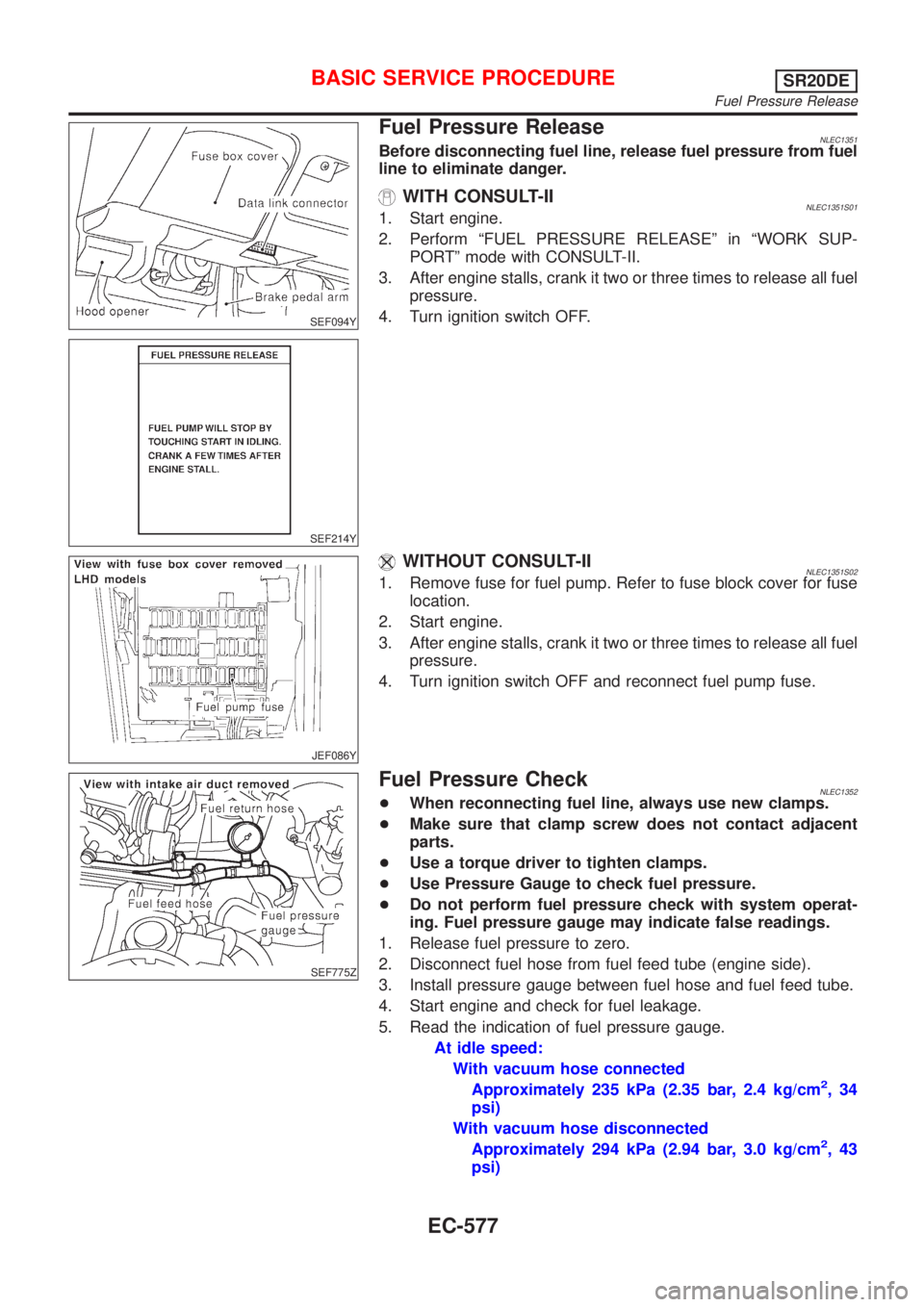
Fuel Pressure ReleaseNLEC1351Before disconnecting fuel line, release fuel pressure from fuel
line to eliminate danger.
WITH CONSULT-IINLEC1351S011. Start engine.
2. Perform ªFUEL PRESSURE RELEASEº in ªWORK SUP-
PORTº mode with CONSULT-II.
3. After engine stalls, crank it two or three times to release all fuel
pressure.
4. Turn ignition switch OFF.
JEF086Y
WITHOUT CONSULT-IINLEC1351S021. Remove fuse for fuel pump. Refer to fuse block cover for fuse
location.
2. Start engine.
3. After engine stalls, crank it two or three times to release all fuel
pressure.
4. Turn ignition switch OFF and reconnect fuel pump fuse.
SEF775Z
Fuel Pressure CheckNLEC1352+When reconnecting fuel line, always use new clamps.
+Make sure that clamp screw does not contact adjacent
parts.
+Use a torque driver to tighten clamps.
+Use Pressure Gauge to check fuel pressure.
+Do not perform fuel pressure check with system operat-
ing. Fuel pressure gauge may indicate false readings.
1. Release fuel pressure to zero.
2. Disconnect fuel hose from fuel feed tube (engine side).
3. Install pressure gauge between fuel hose and fuel feed tube.
4. Start engine and check for fuel leakage.
5. Read the indication of fuel pressure gauge.
At idle speed:
With vacuum hose connected
Approximately 235 kPa (2.35 bar, 2.4 kg/cm
2,34
psi)
With vacuum hose disconnected
Approximately 294 kPa (2.94 bar, 3.0 kg/cm
2,43
psi)
BASIC SERVICE PROCEDURESR20DE
Fuel Pressure Release
EC-577
Page 1003 of 3051
If results are unsatisfactory, perform Fuel Pressure Regulator
Check, EC-578.
SEF718B
Fuel Pressure Regulator CheckNLEC13531. Stop engine and disconnect fuel pressure regulator vacuum
hose from intake manifold collector.
2. Plug intake manifold collector with a rubber cap.
3. Connect variable vacuum source to fuel pressure regulator.
4. Start engine and read indication of fuel pressure gauge as
vacuum is changed.
Fuel pressure should decrease as vacuum increases. If results
are unsatisfactory, replace fuel pressure regulator.
Injector
REMOVAL AND INSTALLATIONNLEC1746
SEF324Z
1. Release fuel pressure to zero.
2. Remove accelerator wire bracket.
3. Remove EVAP canister purge volume control solenoid valve
and the bracket.
BASIC SERVICE PROCEDURESR20DE
Fuel Pressure Regulator Check
EC-578
Page 1004 of 3051

4. Remove ventilation hose.
5. Disconnect injector harness connectors.
6. Disconnect fuel pressure regulator vacuum hose from intake
manifold collector.
7. Disconnect fuel hoses from fuel tube assembly.
8. Remove injectors with fuel tube assembly.
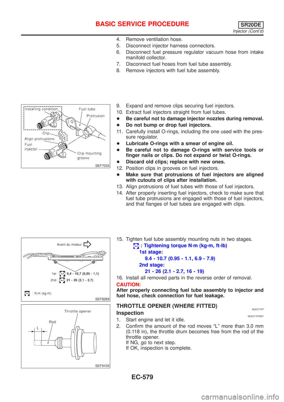
SEF703X
9. Expand and remove clips securing fuel injectors.
10. Extract fuel injectors straight from fuel tubes.
+Be careful not to damage injector nozzles during removal.
+Do not bump or drop fuel injectors.
11. Carefully install O-rings, including the one used with the pres-
sure regulator.
+Lubricate O-rings with a smear of engine oil.
+Be careful not to damage O-rings with service tools or
finger nails or clips. Do not expand or twist O-rings.
+Discard old clips; replace with new ones.
12. Position clips in grooves on fuel injectors.
+Make sure that protrusions of fuel injectors are aligned
with cutouts of clips after installation.
13. Align protrusions of fuel tubes with those of fuel injectors.
14. After properly inserting fuel injectors, check to make sure that
fuel tube protrusions are engaged with those of fuel injectors,
and that flanges of fuel tubes are engaged with clips.
SEF828X
15. Tighten fuel tube assembly mounting nuts in two stages.
: Tightening torque N´m (kg-m, ft-lb)
1st stage:
9.4 - 10.7 (0.95 - 1.1, 6.9 - 7.9)
2nd stage:
21 - 26 (2.1 - 2.7, 16 - 19)
16. Install all removed parts in the reverse order of removal.
CAUTION:
After properly connecting fuel tube assembly to injector and
fuel hose, check connection for fuel leakage.
SEF910X
THROTTLE OPENER (WHERE FITTED)NLEC1747InspectionNLEC1747S011. Start engine and let it idle.
2. Confirm the amount of the rod moves ªLº more than 3.0 mm
(0.118 in), the throttle drum becomes free from the rod of the
throttle opener.
If NG, go to next step.
If OK, inspection is complete.
BASIC SERVICE PROCEDURESR20DE
Injector (Cont'd)
EC-579
Page 1005 of 3051

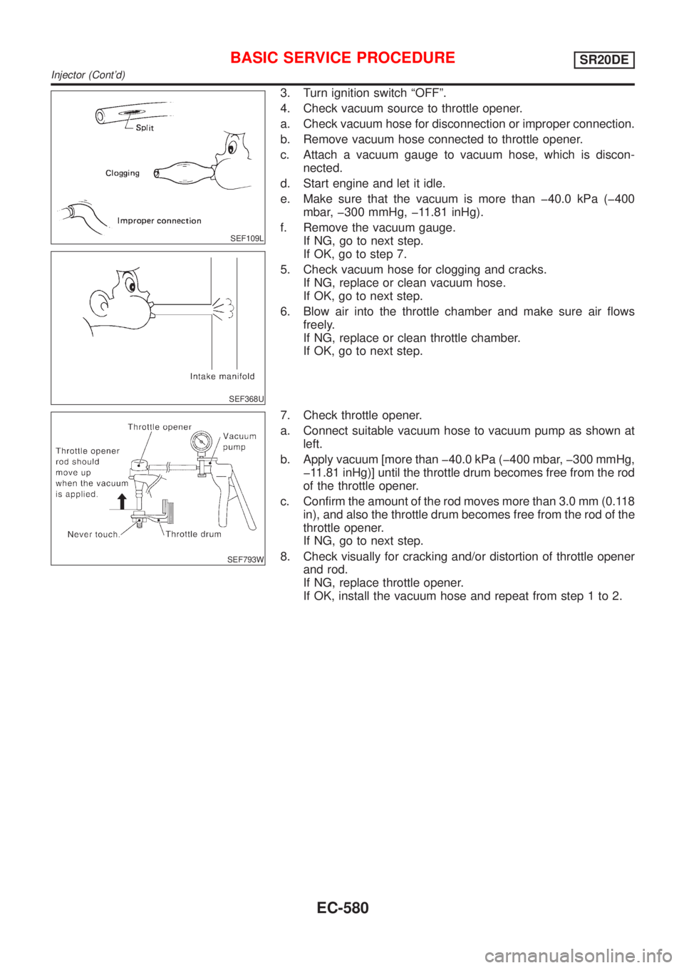
SEF109L
SEF368U
3. Turn ignition switch ªOFFº.
4. Check vacuum source to throttle opener.
a. Check vacuum hose for disconnection or improper connection.
b. Remove vacuum hose connected to throttle opener.
c. Attach a vacuum gauge to vacuum hose, which is discon-
nected.
d. Start engine and let it idle.
e. Make sure that the vacuum is more than þ40.0 kPa (þ400
mbar, þ300 mmHg, þ11.81 inHg).
f. Remove the vacuum gauge.
If NG, go to next step.
If OK, go to step 7.
5. Check vacuum hose for clogging and cracks.
If NG, replace or clean vacuum hose.
If OK, go to next step.
6. Blow air into the throttle chamber and make sure air flows
freely.
If NG, replace or clean throttle chamber.
If OK, go to next step.
SEF793W
7. Check throttle opener.
a. Connect suitable vacuum hose to vacuum pump as shown at
left.
b. Apply vacuum [more than þ40.0 kPa (þ400 mbar, þ300 mmHg,
þ11.81 inHg)] until the throttle drum becomes free from the rod
of the throttle opener.
c. Confirm the amount of the rod moves more than 3.0 mm (0.118
in), and also the throttle drum becomes free from the rod of the
throttle opener.
If NG, go to next step.
8. Check visually for cracking and/or distortion of throttle opener
and rod.
If NG, replace throttle opener.
If OK, install the vacuum hose and repeat from step 1 to 2.
BASIC SERVICE PROCEDURESR20DE
Injector (Cont'd)
EC-580