2001 NISSAN ALMERA TINO service
[x] Cancel search: servicePage 2168 of 3051
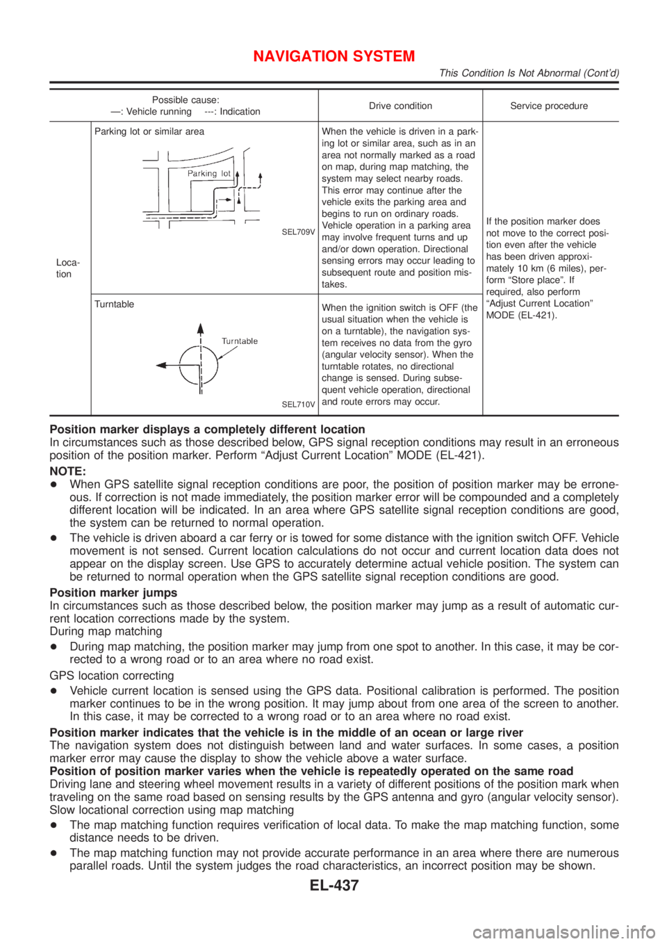
Possible cause:
Ð: Vehicle running ---: IndicationDrive condition Service procedure
Loca-
tionParking lot or similar area
SEL709V
When the vehicle is driven in a park-
ing lot or similar area, such as in an
area not normally marked as a road
on map, during map matching, the
system may select nearby roads.
This error may continue after the
vehicle exits the parking area and
begins to run on ordinary roads.
Vehicle operation in a parking area
may involve frequent turns and up
and/or down operation. Directional
sensing errors may occur leading to
subsequent route and position mis-
takes.If the position marker does
not move to the correct posi-
tion even after the vehicle
has been driven approxi-
mately 10 km (6 miles), per-
form ªStore placeº. If
required, also perform
ªAdjust Current Locationº
MODE (EL-421). Turntable
SEL710V
When the ignition switch is OFF (the
usual situation when the vehicle is
on a turntable), the navigation sys-
tem receives no data from the gyro
(angular velocity sensor). When the
turntable rotates, no directional
change is sensed. During subse-
quent vehicle operation, directional
and route errors may occur.
Position marker displays a completely different location
In circumstances such as those described below, GPS signal reception conditions may result in an erroneous
position of the position marker. Perform ªAdjust Current Locationº MODE (EL-421).
NOTE:
+When GPS satellite signal reception conditions are poor, the position of position marker may be errone-
ous. If correction is not made immediately, the position marker error will be compounded and a completely
different location will be indicated. In an area where GPS satellite signal reception conditions are good,
the system can be returned to normal operation.
+The vehicle is driven aboard a car ferry or is towed for some distance with the ignition switch OFF. Vehicle
movement is not sensed. Current location calculations do not occur and current location data does not
appear on the display screen. Use GPS to accurately determine actual vehicle position. The system can
be returned to normal operation when the GPS satellite signal reception conditions are good.
Position marker jumps
In circumstances such as those described below, the position marker may jump as a result of automatic cur-
rent location corrections made by the system.
During map matching
+During map matching, the position marker may jump from one spot to another. In this case, it may be cor-
rected to a wrong road or to an area where no road exist.
GPS location correcting
+Vehicle current location is sensed using the GPS data. Positional calibration is performed. The position
marker continues to be in the wrong position. It may jump about from one area of the screen to another.
In this case, it may be corrected to a wrong road or to an area where no road exist.
Position marker indicates that the vehicle is in the middle of an ocean or large river
The navigation system does not distinguish between land and water surfaces. In some cases, a position
marker error may cause the display to show the vehicle above a water surface.
Position of position marker varies when the vehicle is repeatedly operated on the same road
Driving lane and steering wheel movement results in a variety of different positions of the position mark when
traveling on the same road based on sensing results by the GPS antenna and gyro (angular velocity sensor).
Slow locational correction using map matching
+The map matching function requires verification of local data. To make the map matching function, some
distance needs to be driven.
+The map matching function may not provide accurate performance in an area where there are numerous
parallel roads. Until the system judges the road characteristics, an incorrect position may be shown.
NAVIGATION SYSTEM
This Condition Is Not Abnormal (Cont'd)
EL-437
Page 2255 of 3051
NLEL0144
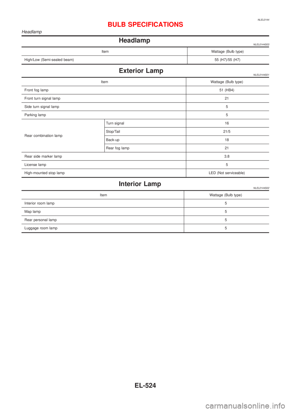
HeadlampNLEL0144S03
Item Wattage (Bulb type)
High/Low (Semi-sealed beam)55 (H7)/55 (H7)
Exterior LampNLEL0144S01
Item Wattage (Bulb type)
Front fog lamp51 (HB4)
Front turn signal lamp21
Side turn signal lamp5
Parking lamp5
Rear combination lampTurn signal 16
Stop/Tail 21/5
Back-up 18
Rear fog lamp 21
Rear side marker lamp3.8
License lamp5
High-mounted stop lampLED (Not serviceable)
Interior LampNLEL0144S02
Item Wattage (Bulb type)
Interior room lamp5
Map lamp5
Rear personal lamp5
Luggage room lamp5
BULB SPECIFICATIONS
Headlamp
EL-524
Page 2258 of 3051
ENGINE MECHANICAL
SECTION
EM
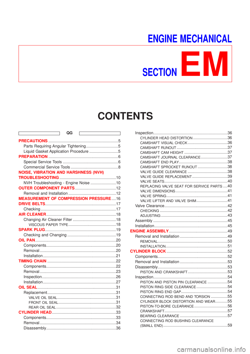
CONTENTS
QG
PRECAUTIONS...............................................................5
Parts Requiring Angular Tightening .............................5
Liquid Gasket Application Procedure ..........................5
PREPARATION...............................................................6
Special Service Tools ..................................................6
Commercial Service Tools ...........................................8
NOISE, VIBRATION AND HARSHNESS (NVH)
TROUBLESHOOTING...................................................10
NVH Troubleshooting - Engine Noise .......................10
OUTER COMPONENT PARTS.....................................12
Removal and Installation ...........................................12
MEASUREMENT OF COMPRESSION PRESSURE....16
DRIVE BELTS................................................................17
Checking ....................................................................17
AIR CLEANER...............................................................18
Changing Air Cleaner Filter .......................................18
VISCOUS PAPER TYPE...........................................18
SPARK PLUG................................................................19
Checking and Changing ............................................19
OIL PAN.........................................................................20
Components...............................................................20
Removal .....................................................................20
Installation ..................................................................21
TIMING CHAIN..............................................................22
Components...............................................................22
Removal .....................................................................23
Inspection...................................................................26
Installation ..................................................................27
OIL SEAL.......................................................................31
Replacement ..............................................................31
VALVE OIL SEAL.....................................................31
FRONT OIL SEAL....................................................31
REAR OIL SEAL......................................................32
CYLINDER HEAD..........................................................33
Components...............................................................33
Removal .....................................................................34
Disassembly...............................................................36Inspection...................................................................36
CYLINDER HEAD DISTORTION...............................36
CAMSHAFT VISUAL CHECK....................................36
CAMSHAFT RUNOUT..............................................37
CAMSHAFT CAM HEIGHT.......................................37
CAMSHAFT JOURNAL CLEARANCE........................37
CAMSHAFT END PLAY............................................38
CAMSHAFT SPROCKET RUNOUT...........................38
VALVE GUIDE CLEARANCE....................................38
VALVE GUIDE REPLACEMENT................................39
VALVE SEATS.........................................................40
REPLACING VALVE SEAT FOR SERVICE PARTS....40
VALVE DIMENSIONS...............................................41
VALVE SPRING.......................................................41
VALVE LIFTER AND VALVE SHIM............................41
Valve Clearance.........................................................42
CHECKING.............................................................42
ADJUSTING............................................................43
Assembly ...................................................................45
Installation ..................................................................45
ENGINE ASSEMBLY.....................................................49
Removal and Installation ...........................................49
REMOVAL...............................................................50
INSTALLATION........................................................51
CYLINDER BLOCK.......................................................52
Components...............................................................52
Removal and Installation ...........................................53
Disassembly...............................................................53
PISTON AND CRANKSHAFT....................................53
Inspection...................................................................54
PISTON AND PISTON PIN CLEARANCE..................54
PISTON RING SIDE CLEARANCE............................54
PISTON RING END GAP..........................................54
CONNECTING ROD BEND AND TORSION...............55
CYLINDER BLOCK DISTORTION AND WEAR...........55
PISTON-TO-BORE CLEARANCE..............................56
CRANKSHAFT.........................................................57
BEARING CLEARANCE...........................................57
CONNECTING ROD BUSHING CLEARANCE
(SMALL END)
..........................................................59
Page 2259 of 3051
REPLACEMENT OF CONNECTING ROD
BUSHING (SMALL END)
..........................................60
FLYWHEEL RUNOUT..............................................60
Assembly ...................................................................60
PISTON..................................................................60
CRANKSHAFT.........................................................61
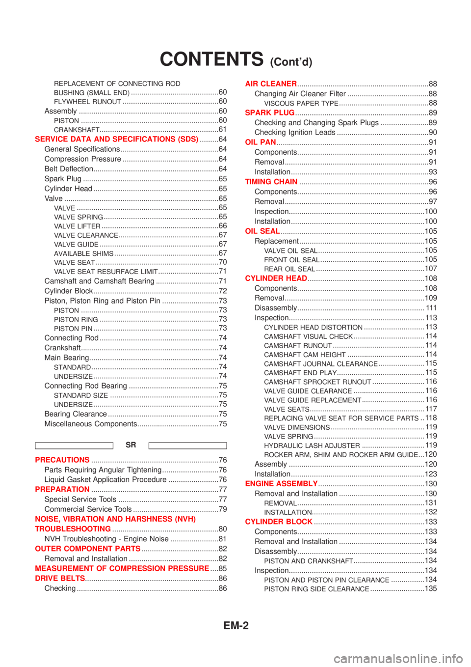
SERVICE DATA AND SPECIFICATIONS (SDS).........64
General Specifications ...............................................64
Compression Pressure ..............................................64
Belt Deflection............................................................64
Spark Plug .................................................................65
Cylinder Head ............................................................65
Valve ..........................................................................65
VALVE....................................................................65
VALVE SPRING.......................................................65
VALVE LIFTER........................................................66
VALVE CLEARANCE................................................67
VALVE GUIDE.........................................................67
AVAILABLE SHIMS..................................................67
VALVE SEAT...........................................................70
VALVE SEAT RESURFACE LIMIT.............................71
Camshaft and Camshaft Bearing ..............................71
Cylinder Block ............................................................72
Piston, Piston Ring and Piston Pin ...........................73
PISTON..................................................................73
PISTON RING.........................................................73
PISTON PIN............................................................73
Connecting Rod .........................................................74
Crankshaft..................................................................74
Main Bearing..............................................................74
STANDARD.............................................................74
UNDERSIZE............................................................74
Connecting Rod Bearing ...........................................75
STANDARD SIZE....................................................75
UNDERSIZE............................................................75
Bearing Clearance .....................................................75
Miscellaneous Components.......................................75
SR
PRECAUTIONS.............................................................76
Parts Requiring Angular Tightening ...........................76
Liquid Gasket Application Procedure ........................76
PREPARATION.............................................................77
Special Service Tools ................................................77
Commercial Service Tools .........................................79
NOISE, VIBRATION AND HARSHNESS (NVH)
TROUBLESHOOTING...................................................80
NVH Troubleshooting - Engine Noise .......................81
OUTER COMPONENT PARTS.....................................82
Removal and Installation ...........................................82
MEASUREMENT OF COMPRESSION PRESSURE....85
DRIVE BELTS................................................................86
Checking ....................................................................86AIR CLEANER...............................................................88
Changing Air Cleaner Filter .......................................88
VISCOUS PAPER TYPE...........................................88
SPARK PLUG................................................................89
Checking and Changing Spark Plugs .......................89
Checking Ignition Leads ............................................90
OIL PAN.........................................................................91
Components...............................................................91
Removal .....................................................................91
Installation ..................................................................93
TIMING CHAIN..............................................................96
Components...............................................................96
Removal .....................................................................97
Inspection.................................................................100
Installation ................................................................100
OIL SEAL.....................................................................105
Replacement ............................................................105
VALVE OIL SEAL...................................................105
FRONT OIL SEAL..................................................105
REAR OIL SEAL....................................................107
CYLINDER HEAD........................................................108
Components.............................................................108
Removal ...................................................................109
Disassembly............................................................. 111
Inspection................................................................. 113
CYLINDER HEAD DISTORTION............................. 113
CAMSHAFT VISUAL CHECK.................................. 114
CAMSHAFT RUNOUT............................................ 114
CAMSHAFT CAM HEIGHT..................................... 114
CAMSHAFT JOURNAL CLEARANCE...................... 115
CAMSHAFT END PLAY.......................................... 115
CAMSHAFT SPROCKET RUNOUT......................... 116
VALVE GUIDE CLEARANCE.................................. 116
VALVE GUIDE REPLACEMENT.............................. 116
VALVE SEATS....................................................... 117
REPLACING VALVE SEAT FOR SERVICE PARTS.. 118
VALVE DIMENSIONS............................................. 119
VALVE SPRING..................................................... 119
HYDRAULIC LASH ADJUSTER.............................. 119
ROCKER ARM, SHIM AND ROCKER ARM GUIDE...120
Assembly .................................................................120
Installation ................................................................123
ENGINE ASSEMBLY...................................................130
Removal and Installation .........................................130
REMOVAL.............................................................131
INSTALLATION......................................................132
CYLINDER BLOCK.....................................................133
Components.............................................................133
Removal and Installation .........................................134
Disassembly.............................................................134
PISTON AND CRANKSHAFT..................................134
Inspection.................................................................134
PISTON AND PISTON PIN CLEARANCE................134
PISTON RING SIDE CLEARANCE..........................135
CONTENTS(Cont'd)
EM-2
Page 2260 of 3051
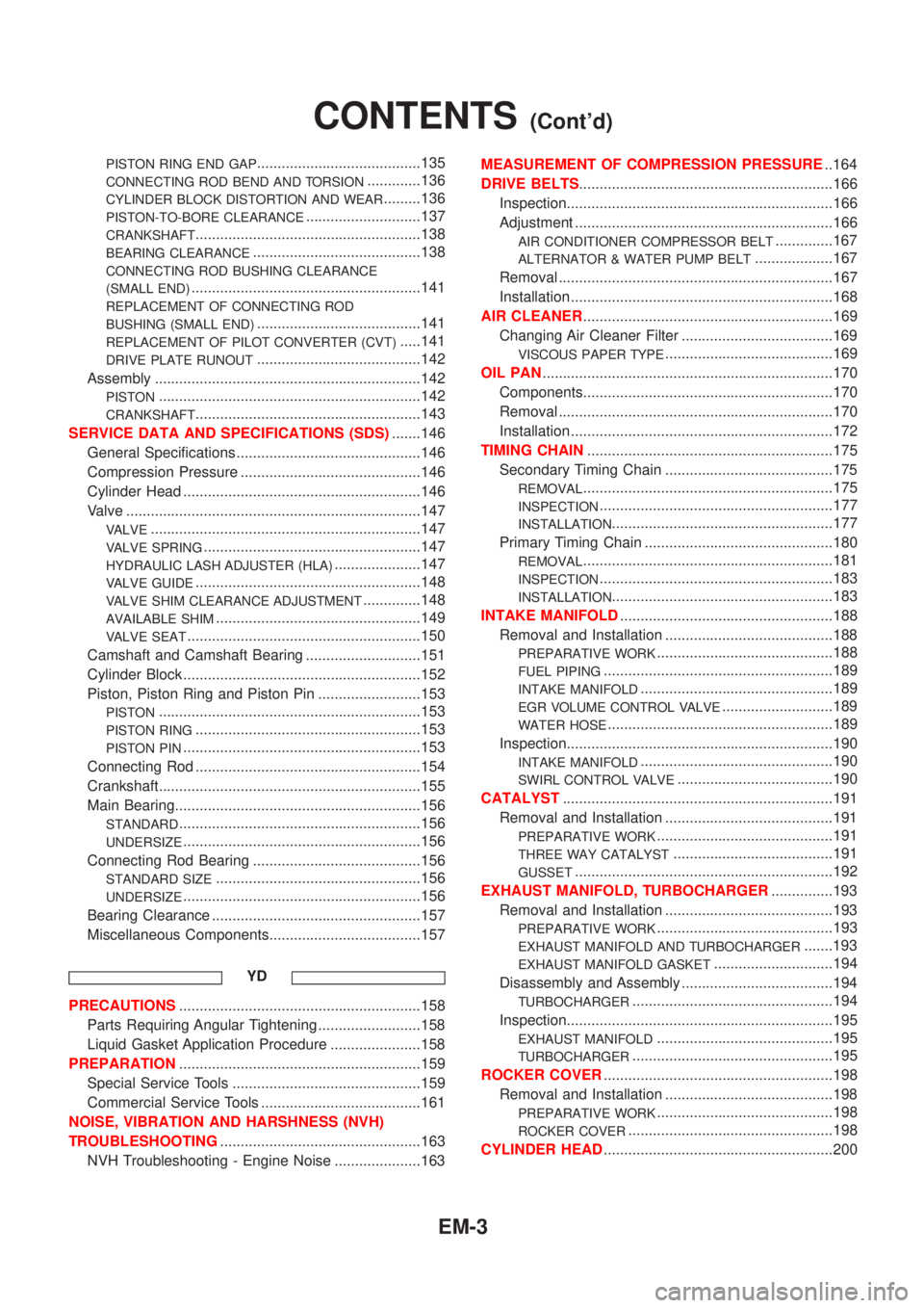
PISTON RING END GAP........................................135
CONNECTING ROD BEND AND TORSION.............136
CYLINDER BLOCK DISTORTION AND WEAR.........136
PISTON-TO-BORE CLEARANCE............................137
CRANKSHAFT.......................................................138
BEARING CLEARANCE.........................................138
CONNECTING ROD BUSHING CLEARANCE
(SMALL END)
........................................................141
REPLACEMENT OF CONNECTING ROD
BUSHING (SMALL END)
........................................141
REPLACEMENT OF PILOT CONVERTER (CVT).....141
DRIVE PLATE RUNOUT........................................142
Assembly .................................................................142
PISTON................................................................142
CRANKSHAFT.......................................................143
SERVICE DATA AND SPECIFICATIONS (SDS).......146
General Specifications .............................................146
Compression Pressure ............................................146
Cylinder Head ..........................................................146
Valve ........................................................................147
VALVE..................................................................147
VALVE SPRING.....................................................147
HYDRAULIC LASH ADJUSTER (HLA).....................147
VALVE GUIDE.......................................................148
VALVE SHIM CLEARANCE ADJUSTMENT..............148
AVAILABLE SHIM..................................................149
VALVE SEAT.........................................................150
Camshaft and Camshaft Bearing ............................151
Cylinder Block ..........................................................152
Piston, Piston Ring and Piston Pin .........................153
PISTON................................................................153
PISTON RING.......................................................153
PISTON PIN..........................................................153
Connecting Rod .......................................................154
Crankshaft................................................................155
Main Bearing............................................................156
STANDARD...........................................................156
UNDERSIZE..........................................................156
Connecting Rod Bearing .........................................156
STANDARD SIZE..................................................156
UNDERSIZE..........................................................156
Bearing Clearance ...................................................157
Miscellaneous Components.....................................157
YD
PRECAUTIONS...........................................................158
Parts Requiring Angular Tightening .........................158
Liquid Gasket Application Procedure ......................158
PREPARATION...........................................................159
Special Service Tools ..............................................159
Commercial Service Tools .......................................161
NOISE, VIBRATION AND HARSHNESS (NVH)
TROUBLESHOOTING.................................................163
NVH Troubleshooting - Engine Noise .....................163MEASUREMENT OF COMPRESSION PRESSURE..164
DRIVE BELTS..............................................................166
Inspection.................................................................166
Adjustment ...............................................................166
AIR CONDITIONER COMPRESSOR BELT..............167
ALTERNATOR & WATER PUMP BELT...................167
Removal ...................................................................167
Installation ................................................................168
AIR CLEANER.............................................................169
Changing Air Cleaner Filter .....................................169
VISCOUS PAPER TYPE.........................................169
OIL PAN.......................................................................170
Components.............................................................170
Removal ...................................................................170
Installation ................................................................172
TIMING CHAIN............................................................175
Secondary Timing Chain .........................................175
REMOVAL.............................................................175
INSPECTION.........................................................177
INSTALLATION......................................................177
Primary Timing Chain ..............................................180
REMOVAL.............................................................181
INSPECTION.........................................................183
INSTALLATION......................................................183
INTAKE MANIFOLD....................................................188
Removal and Installation .........................................188
PREPARATIVE WORK...........................................188
FUEL PIPING........................................................189
INTAKE MANIFOLD...............................................189
EGR VOLUME CONTROL VALVE...........................189
WATER HOSE.......................................................189
Inspection.................................................................190
INTAKE MANIFOLD...............................................190
SWIRL CONTROL VALVE......................................190
CATALYST..................................................................191
Removal and Installation .........................................191
PREPARATIVE WORK...........................................191
THREE WAY CATALYST.......................................191
GUSSET...............................................................192
EXHAUST MANIFOLD, TURBOCHARGER...............193
Removal and Installation .........................................193
PREPARATIVE WORK...........................................193
EXHAUST MANIFOLD AND TURBOCHARGER.......193
EXHAUST MANIFOLD GASKET.............................194
Disassembly and Assembly .....................................194
TURBOCHARGER.................................................194
Inspection.................................................................195
EXHAUST MANIFOLD...........................................195
TURBOCHARGER.................................................195
ROCKER COVER........................................................198
Removal and Installation .........................................198
PREPARATIVE WORK...........................................198
ROCKER COVER..................................................198
CYLINDER HEAD........................................................200
CONTENTS(Cont'd)
EM-3
Page 2261 of 3051
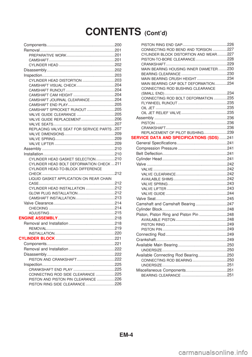
Components.............................................................200
Removal ...................................................................201
PREPARATIVE WORK...........................................201
CAMSHAFT...........................................................201
CYLINDER HEAD..................................................202
Disassembly.............................................................202
Inspection.................................................................203
CYLINDER HEAD DISTORTION.............................203
CAMSHAFT VISUAL CHECK..................................204
CAMSHAFT RUNOUT............................................204
CAMSHAFT CAM HEIGHT.....................................204
CAMSHAFT JOURNAL CLEARANCE......................204
CAMSHAFT END PLAY..........................................205
CAMSHAFT SPROCKET RUNOUT.........................205
VALVE GUIDE CLEARANCE..................................205
VALVE GUIDE REPLACEMENT..............................206
VALVE SEATS.......................................................207
REPLACING VALVE SEAT FOR SERVICE PARTS..207
VALVE DIMENSIONS.............................................209
VALVE SPRING.....................................................209
VALVE LIFTER......................................................209
Assembly .................................................................210
Installation ................................................................210
CYLINDER HEAD GASKET SELECTION.................210
CYLINDER HEAD BOLT DEFORMATION CHECK... 211
CYLINDER HEAD-TO-BLOCK DIFFERENCE
CHECK
.................................................................212
LIQUID GASKET APPLICATION ON REAR CHAIN
CASE
....................................................................212
CYLINDER HEAD INSTALLATION..........................212
GLOW PLUG INSTALLATION.................................212
CAMSHAFT INSTALLATION...................................213
Valve Clearance.......................................................214
CHECKING...........................................................214
ADJUSTING..........................................................215
ENGINE ASSEMBLY...................................................218
Removal and Installation .........................................218
REMOVAL.............................................................219
INSTALLATION......................................................220
CYLINDER BLOCK.....................................................221
Components.............................................................221
Removal and Installation .........................................222
Disassembly.............................................................222
PISTON AND CRANKSHAFT..................................222
Inspection.................................................................225
CRANKSHAFT END PLAY.....................................225
CONNECTING ROD SIDE CLEARANCE.................225
PISTON AND PISTON PIN CLEARANCE................226
PISTON RING SIDE CLEARANCE..........................226
PISTON RING END GAP........................................226
CONNECTING ROD BEND AND TORSION.............227
CYLINDER BLOCK DISTORTION AND WEAR.........227
PISTON-TO-BORE CLEARANCE............................228
CRANKSHAFT.......................................................229
MAIN BEARING HOUSING INNER DIAMETER........230
BEARING CLEARANCE.........................................230
MAIN BEARING CRUSH HEIGHT...........................234
MAIN BEARING CAP BOLT DEFORMATION...........234
CONNECTING ROD BUSHING CLEARANCE
(SMALL END)
........................................................234
CONNECTING ROD BOLT DEFORMATION............235
FLYWHEEL RUNOUT............................................235
OIL JET................................................................235
OIL JET RELIEF VALVE.........................................235
Assembly .................................................................236
PISTON................................................................236
CRANKSHAFT.......................................................236
REPLACEMENT OF PILOT BUSHING.....................239
SERVICE DATA AND SPECIFICATIONS (SDS).......241
General Specifications .............................................241
Compression Pressure ............................................241
Belt Deflection..........................................................241
Cylinder Head ..........................................................241
Valve ........................................................................242
VALVE..................................................................242
VALVE CLEARANCE..............................................242
AVAILABLE SHIMS................................................242
VALVE SPRING.....................................................243
VALVE LIFTER......................................................243
VALVE GUIDE.......................................................244
Valve Seat................................................................245
Camshaft and Camshaft Bearing ............................247
Cylinder Block ..........................................................248
Piston, Piston Ring and Piston Pin .........................248
AVAILABLE PISTON..............................................248
PISTON RING.......................................................249
PISTON PIN..........................................................249
Connecting Rod .......................................................249
Crankshaft................................................................249
Available Main Bearing ............................................250
UNDERSIZE..........................................................250
Available Connecting Rod Bearing..........................250
CONNECTING ROD BEARING...............................250
UNDERSIZE..........................................................251
Miscellaneous Components.....................................251
BEARING CLEARANCE.........................................251
CONTENTS(Cont'd)
EM-4
Page 2263 of 3051
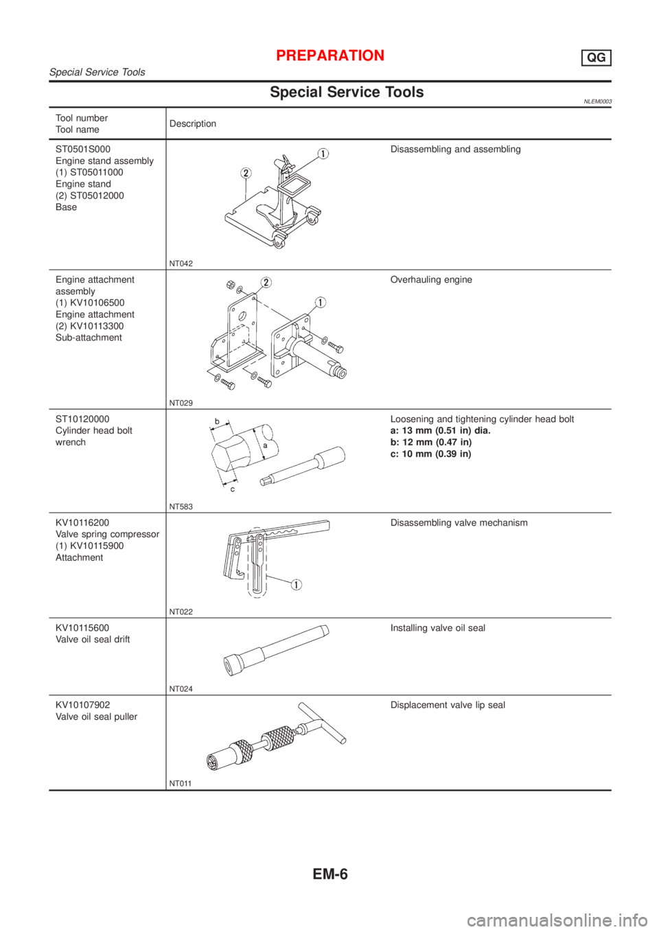
Special Service ToolsNLEM0003
Tool number
Tool nameDescription
ST0501S000
Engine stand assembly
(1) ST05011000
Engine stand
(2) ST05012000
Base
NT042
Disassembling and assembling
Engine attachment
assembly
(1) KV10106500
Engine attachment
(2) KV10113300
Sub-attachment
NT029
Overhauling engine
ST10120000
Cylinder head bolt
wrench
NT583
Loosening and tightening cylinder head bolt
a: 13 mm (0.51 in) dia.
b: 12 mm (0.47 in)
c: 10 mm (0.39 in)
KV10116200
Valve spring compressor
(1) KV10115900
Attachment
NT022
Disassembling valve mechanism
KV10115600
Valve oil seal drift
NT024
Installing valve oil seal
KV10107902
Valve oil seal puller
NT011
Displacement valve lip seal
PREPARATIONQG
Special Service Tools
EM-6
Page 2264 of 3051
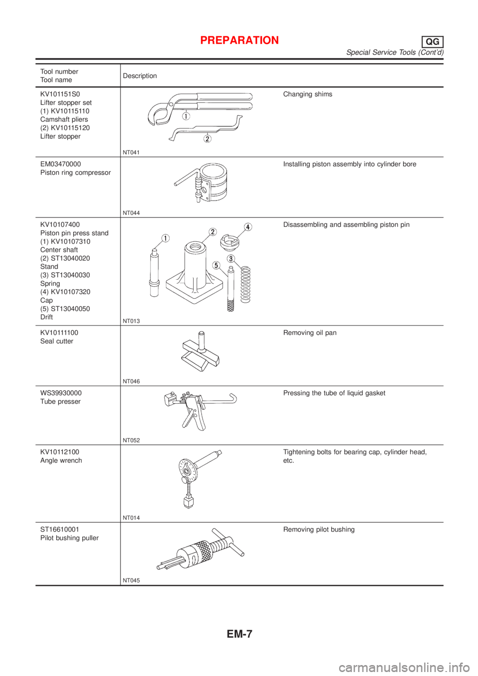
Tool number
Tool nameDescription
KV101151S0
Lifter stopper set
(1) KV10115110
Camshaft pliers
(2) KV10115120
Lifter stopper
NT041
Changing shims
EM03470000
Piston ring compressor
NT044
Installing piston assembly into cylinder bore
KV10107400
Piston pin press stand
(1) KV10107310
Center shaft
(2) ST13040020
Stand
(3) ST13040030
Spring
(4) KV10107320
Cap
(5) ST13040050
Drift
NT013
Disassembling and assembling piston pin
KV101111 0 0
Seal cutter
NT046
Removing oil pan
WS39930000
Tube presser
NT052
Pressing the tube of liquid gasket
KV10112100
Angle wrench
NT014
Tightening bolts for bearing cap, cylinder head,
etc.
ST16610001
Pilot bushing puller
NT045
Removing pilot bushing
PREPARATIONQG
Special Service Tools (Cont'd)
EM-7