Page 2396 of 3051

AEM026
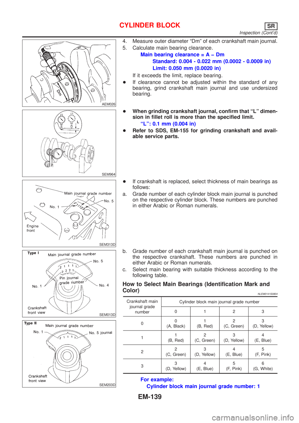
4. Measure outer diameter ªDmº of each crankshaft main journal.
5. Calculate main bearing clearance.
Main bearing clearance = A þ Dm
Standard: 0.004 - 0.022 mm (0.0002 - 0.0009 in)
Limit: 0.050 mm (0.0020 in)
If it exceeds the limit, replace bearing.
+If clearance cannot be adjusted within the standard of any
bearing, grind crankshaft main journal and use undersized
bearing.
SEM964
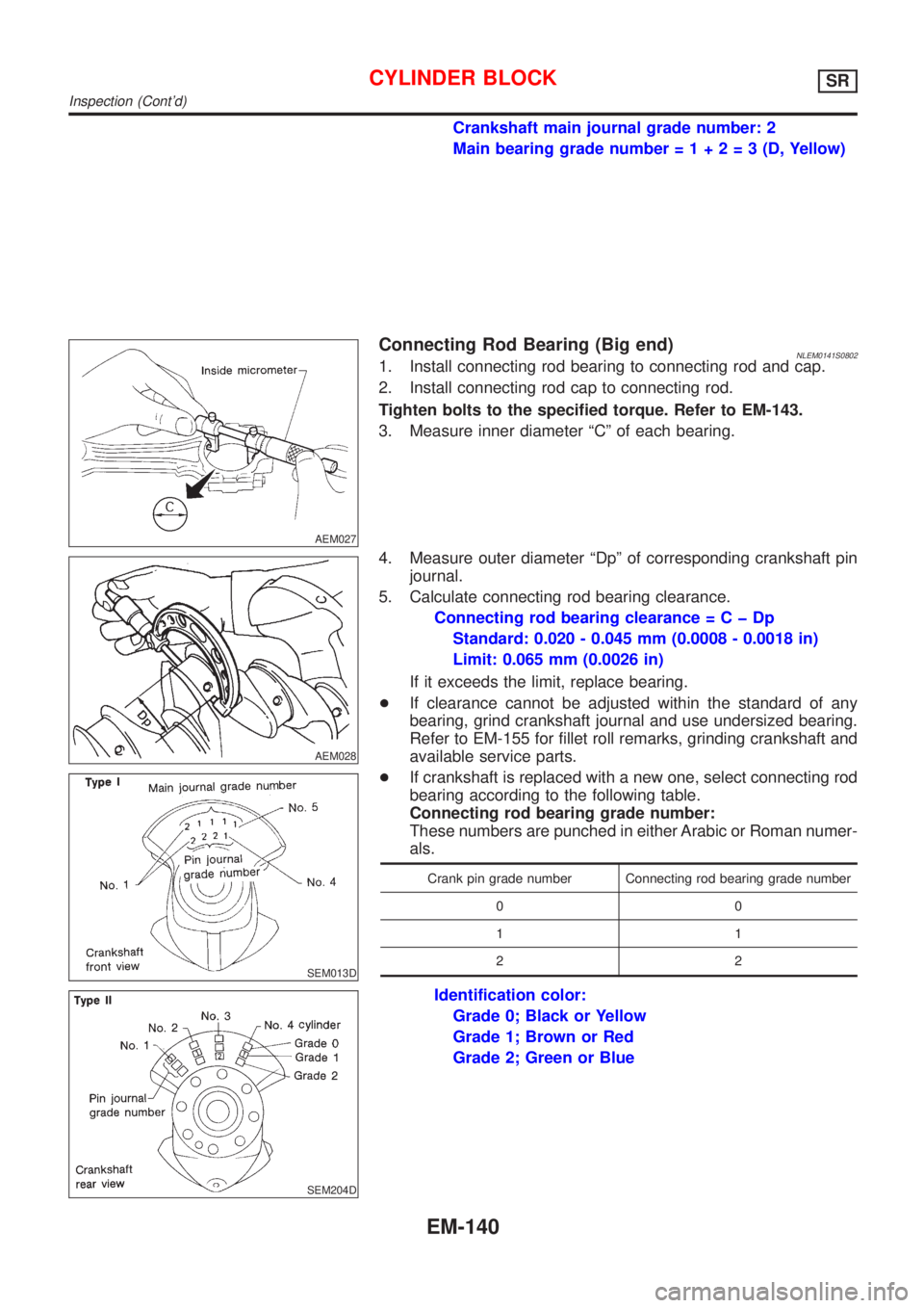
+When grinding crankshaft journal, confirm that ªLº dimen-
sion in fillet roll is more than the specified limit.
ªLº: 0.1 mm (0.004 in)
+Refer to SDS, EM-155 for grinding crankshaft and avail-
able service parts.
SEM313D
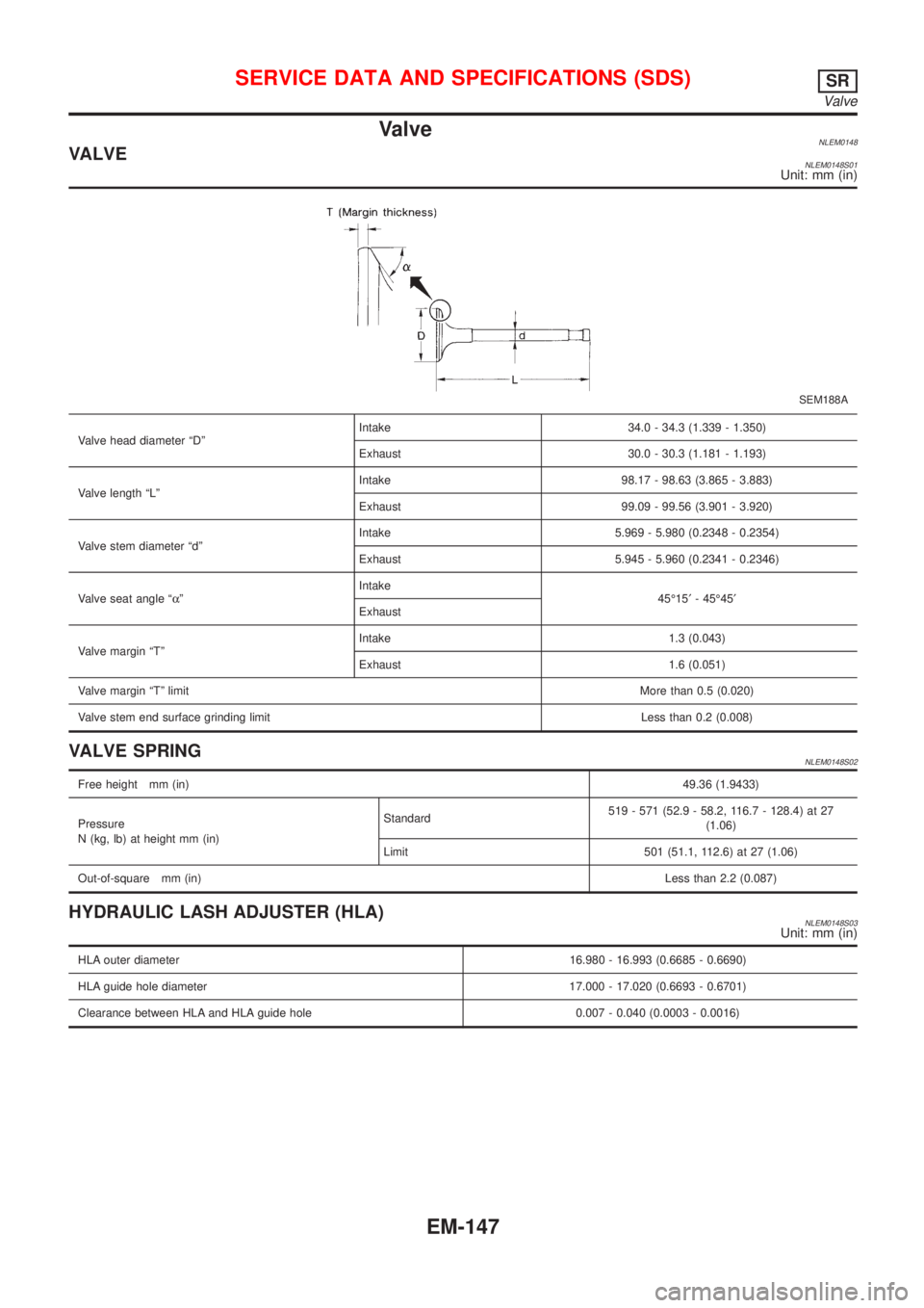
+If crankshaft is replaced, select thickness of main bearings as
follows:
a. Grade number of each cylinder block main journal is punched
on the respective cylinder block. These numbers are punched
in either Arabic or Roman numerals.
SEM013D
SEM203D
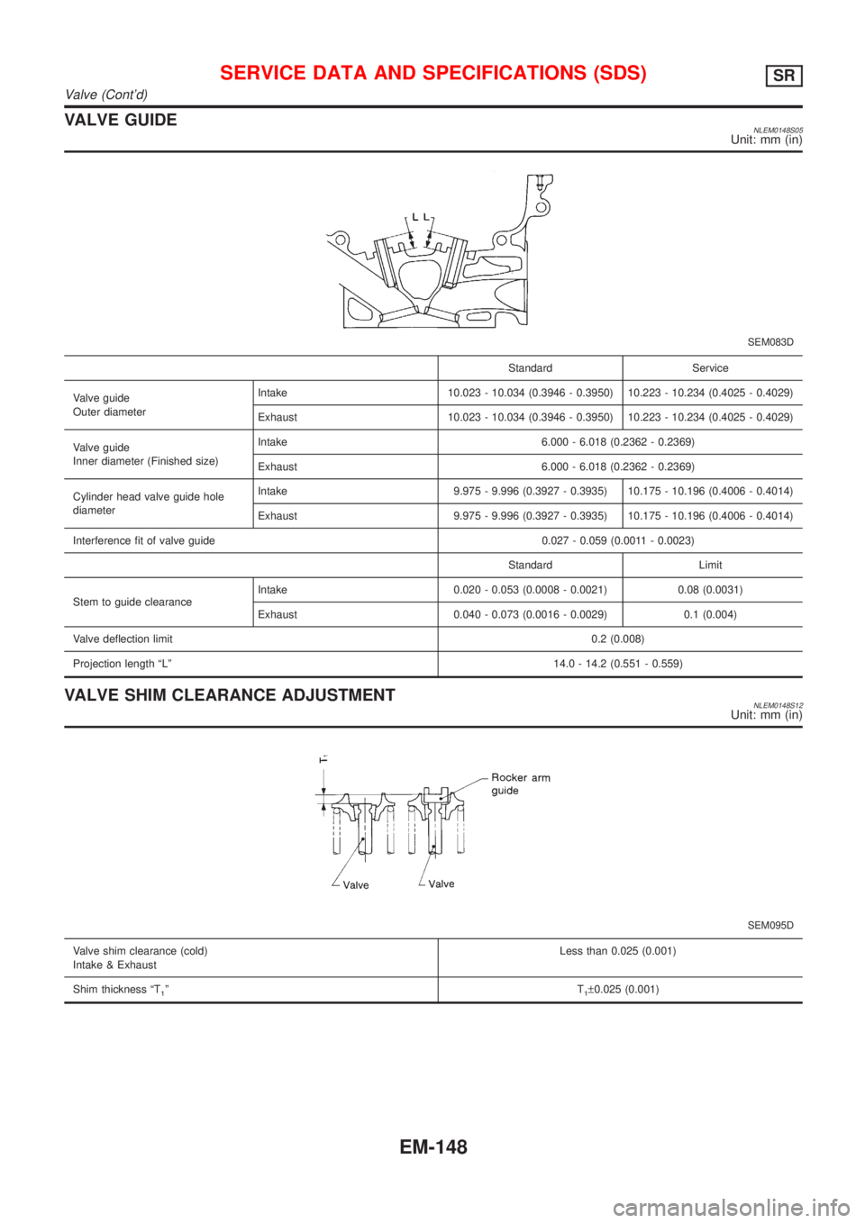
b. Grade number of each crankshaft main journal is punched on
the respective crankshaft. These numbers are punched in
either Arabic or Roman numerals.
c. Select main bearing with suitable thickness according to the
following table.
How to Select Main Bearings (Identification Mark and
Color)
NLEM0141S0804
Crankshaft main
journal grade
numberCylinder block main journal grade number
0123
00
(A, Black)1
(B, Red)2
(C, Green)3
(D, Yellow)
11
(B, Red)2
(C, Green)3
(D, Yellow)4
(E, Blue)
22
(C, Green)3
(D, Yellow)4
(E, Blue)5
(F, Pink)
33
(D, Yellow)4
(E, Blue)5
(F, Pink)6
(G, White)
For example:
Cylinder block main journal grade number: 1
CYLINDER BLOCKSR
Inspection (Cont'd)
EM-139
Page 2397 of 3051

Crankshaft main journal grade number: 2
Main bearing grade number=1+2=3(D,Yellow)
AEM027
Connecting Rod Bearing (Big end)NLEM0141S08021. Install connecting rod bearing to connecting rod and cap.
2. Install connecting rod cap to connecting rod.
Tighten bolts to the specified torque. Refer to EM-143.
3. Measure inner diameter ªCº of each bearing.
AEM028
SEM013D
SEM204D
4. Measure outer diameter ªDpº of corresponding crankshaft pin
journal.
5. Calculate connecting rod bearing clearance.
Connecting rod bearing clearance=CþDp
Standard: 0.020 - 0.045 mm (0.0008 - 0.0018 in)
Limit: 0.065 mm (0.0026 in)
If it exceeds the limit, replace bearing.
+If clearance cannot be adjusted within the standard of any
bearing, grind crankshaft journal and use undersized bearing.
Refer to EM-155 for fillet roll remarks, grinding crankshaft and
available service parts.
+If crankshaft is replaced with a new one, select connecting rod
bearing according to the following table.
Connecting rod bearing grade number:
These numbers are punched in either Arabic or Roman numer-
als.
Crank pin grade number Connecting rod bearing grade number
00
11
22
Identification color:
Grade 0; Black or Yellow
Grade 1; Brown or Red
Grade 2; Green or Blue
CYLINDER BLOCKSR
Inspection (Cont'd)
EM-140
Page 2403 of 3051
General SpecificationsNLEM0143
Cylinder arrangementIn-line 4
Displacement cm
3(cu in)1,998 (121.92)
Bore and stroke mm (in)86´86 (3.39´3.39)
Valve arrangementDOHC
Firing order1-3-4-2
Number of piston ringsCompression 2
Oil 1
Number of main bearings5
Compression ratio10.0
Valve timing
Unit: degree
EM120
abcde f
232É 240É 6É 54É 3É 49É
Compression PressureNLEM0144Unit: kPa (kg/cm2, psi)/300 rpm
Compression pressureStandard 1,275 (13.01, 184.9)
Minimum 1,079 (11.01, 156.5)
Differential limit between cylinders 98 (1.0, 14)
Cylinder HeadNLEM0147Unit: mm (in)
SEM043F
Standard Limit
Head surface distortion Less than 0.03 (0.0012) 0.1 (0.004)
Nominal cylinder head
height ªHº136.9 - 137.1 (5.390 - 5.398)
Resurfacing limit 0.2 (0.008)*
*Total amount of cylinder head resurfacing plus cylinder block resurfacing
SERVICE DATA AND SPECIFICATIONS (SDS)SR
General Specifications
EM-146
Page 2404 of 3051

ValveNLEM0148VALVENLEM0148S01Unit: mm (in)
SEM188A
Valve head diameter ªDºIntake 34.0 - 34.3 (1.339 - 1.350)
Exhaust 30.0 - 30.3 (1.181 - 1.193)
Valve length ªLºIntake 98.17 - 98.63 (3.865 - 3.883)
Exhaust 99.09 - 99.56 (3.901 - 3.920)
Valve stem diameter ªdºIntake 5.969 - 5.980 (0.2348 - 0.2354)
Exhaust 5.945 - 5.960 (0.2341 - 0.2346)
Valve seat angle ªaºIntake
45É15¢- 45É45¢
Exhaust
Valve margin ªTºIntake 1.3 (0.043)
Exhaust 1.6 (0.051)
Valve margin ªTº limitMore than 0.5 (0.020)
Valve stem end surface grinding limit Less than 0.2 (0.008)
VALVE SPRINGNLEM0148S02
Free height mm (in)49.36 (1.9433)
Pressure
N (kg, lb) at height mm (in)Standard519 - 571 (52.9 - 58.2, 116.7 - 128.4) at 27
(1.06)
Limit 501 (51.1, 112.6) at 27 (1.06)
Out-of-square mm (in)Less than 2.2 (0.087)
HYDRAULIC LASH ADJUSTER (HLA)NLEM0148S03Unit: mm (in)
HLA outer diameter16.980 - 16.993 (0.6685 - 0.6690)
HLA guide hole diameter 17.000 - 17.020 (0.6693 - 0.6701)
Clearance between HLA and HLA guide hole 0.007 - 0.040 (0.0003 - 0.0016)
SERVICE DATA AND SPECIFICATIONS (SDS)SR
Valve
EM-147
Page 2405 of 3051

VALVE GUIDENLEM0148S05Unit: mm (in)
SEM083D
Standard Service
Valve guide
Outer diameterIntake 10.023 - 10.034 (0.3946 - 0.3950) 10.223 - 10.234 (0.4025 - 0.4029)
Exhaust 10.023 - 10.034 (0.3946 - 0.3950) 10.223 - 10.234 (0.4025 - 0.4029)
Valve guide
Inner diameter (Finished size)Intake 6.000 - 6.018 (0.2362 - 0.2369)
Exhaust 6.000 - 6.018 (0.2362 - 0.2369)
Cylinder head valve guide hole
diameterIntake 9.975 - 9.996 (0.3927 - 0.3935) 10.175 - 10.196 (0.4006 - 0.4014)
Exhaust 9.975 - 9.996 (0.3927 - 0.3935) 10.175 - 10.196 (0.4006 - 0.4014)
Interference fit of valve guide 0.027 - 0.059 (0.0011 - 0.0023)
Standard Limit
Stem to guide clearanceIntake 0.020 - 0.053 (0.0008 - 0.0021) 0.08 (0.0031)
Exhaust 0.040 - 0.073 (0.0016 - 0.0029) 0.1 (0.004)
Valve deflection limit0.2 (0.008)
Projection length ªLº14.0 - 14.2 (0.551 - 0.559)
VALVE SHIM CLEARANCE ADJUSTMENTNLEM0148S12Unit: mm (in)
SEM095D
Valve shim clearance (cold)
Intake & ExhaustLess than 0.025 (0.001)
Shim thickness ªT
1ºT1±0.025 (0.001)
SERVICE DATA AND SPECIFICATIONS (SDS)SR
Valve (Cont'd)
EM-148
Page 2406 of 3051
AVAILABLE SHIMNLEM0148S06Unit: mm (in)
AEM236
Thickness mm (in) Identification mark
2.800 (0.1102)28
00
2.825 (0.1112)28
25
2.850 (0.1122)28
50
2.875 (0.1132)28
75
2.900 (0.1142)29
00
2.925 (0.1152)29
25
2.950 (0.1161)29
50
2.975 (0.1171)29
75
3.000 (0.1181)30
00
3.025 (0.1191)30
25
3.050 (0.1201)30
50
3.075 (0.1211)30
75
3.100 (0.1220)31
00
3.125 (0.1230)31
25
3.150 (0.1240)31
50
3.175 (0.1250)31
75
3.200 (0.1260)32
00
SERVICE DATA AND SPECIFICATIONS (SDS)SR
Valve (Cont'd)
EM-149
Page 2407 of 3051
VALVE SEATNLEM0148S07
SEM651DB
Standard Service
Cylinder head seat recess diameter (D)In. 35.000 - 35.016 (1.3780 - 1.3786) 35.500 - 35.516 (1.3976 - 1.3983)
Ex. 31.000 - 31.016 (1.2205 - 1.2211) 31.500 - 31.516 (1.2402 - 1.2408)
Valve seat interference fitIn. 0.064 - 0.096 (0.0025 - 0.0038)
Ex. 0.064 - 0.096 (0.0025 - 0.0038)
Valve seat outer diameter (d)In. 35.080 - 35.096 (1.3811 - 1.3817) 35.580 - 35.596 (1.4008 - 1.4014)
Ex. 31.080 - 31.096 (1.2236 - 1.2242) 31.580 - 31.596 (1.2433 - 1.2439)
Depth (H)In. 6.25 (0.2461)
Ex. 6.25 (0.2461)
Height (h) 6.2 - 6.3 (0.244 - 0.248) 5.4 - 5.5 (0.213 - 0.217)
SERVICE DATA AND SPECIFICATIONS (SDS)SR
Valve (Cont'd)
EM-150
Page 2408 of 3051
Camshaft and Camshaft BearingNLEM0149Unit: mm (in)
Standard Limit
Camshaft journal to bearing clearance 0.030 - 0.071 (0.0012 - 0.0028) 0.15 (0.0059)
Inner diameter of camshaft bearing 28.000 - 28.021 (1.1024 - 1.1032) Ð
Outer diameter of camshaft journal 27.935 - 27.955 (1.0998 - 1.1006) Ð
Camshaft runout [TIR*] Less than 0.02 (0.0008) 0.1 (0.004)
Camshaft sprocket runout [TIR*] Less than 0.25 (0.0098) Ð
Camshaft end play 0.055 - 0.139 (0.0022 - 0.0055) 0.20 (0.0079)
EM671
Cam height ªAºIntake 37.775 (1.4872)
Exhaust 37.404 (1.4726)
Wear limit of cam height0.2 (0.008)
*Total indicator reading
SERVICE DATA AND SPECIFICATIONS (SDS)SR
Camshaft and Camshaft Bearing
EM-151