Page 2332 of 3051
Connecting Rod BearingNLEM0038STANDARD SIZENLEM0038S01Unit: mm (in)
Grade No. Thickness Identification color or number
0 1.503 - 1.506 (0.0592 - 0.0593) Ð
1 1.506 - 1.509 (0.0593 - 0.0594) Brown
2 1.509 - 1.512 (0.0594 - 0.0595) Green
UNDERSIZENLEM0038S02Unit: mm (in)
Grade No. Thickness Identification color or number
0.08 (0.0031) 1.542 - 1.546 (0.0607 - 0.0609) Ð
0.12 (0.0047) 1.562 - 1.566 (0.0615 - 0.0617) Ð
0.25 (0.0098) 1.627 - 1.631 (0.0641 - 0.0642) Ð
Bearing ClearanceNLEM0039Unit: mm (in)
Main bearing clearanceStandard 0.020 - 0.044 (0.0008 - 0.0017)
Limit 0.1 (0.004)
Connecting rod bearing clearanceStandard 0.014 - 0.039 (0.0006 - 0.0015)
Limit 0.1 (0.004)
Miscellaneous ComponentsNLEM0040Unit: mm (in)
Flywheel runout [TIR*]Less than 0.15 (0.0059)
Camshaft sprocket runout [TIR*] Less than 0.15 (0.0059)
*: Total indicator reading
SERVICE DATA AND SPECIFICATIONS (SDS)QG
Connecting Rod Bearing
EM-75
Page 2334 of 3051
Special Service ToolsNLEM0114
Tool number
Tool nameDescription
ST0501S000
Engine stand assembly
1 ST05011000
Engine stand
2 ST05012000
Base
NT042
Disassembling and assembling
KV10106500
Engine stand shaft
NT028
KV10115300
Engine sub-attachment
NT008
ST10120000
Cylinder head bolt
wrench
NT583
Loosening and tightening cylinder head bolt
a: 13 (0.51) dia.
b: 12 (0.47)
c: 10 (0.39)
Unit: mm (in)
KV10116200
Valve spring compressor
1 KV10115900
Attachment
NT022
Disassembling valve mechanism
KV10115600
Valve oil seal drift
NT024
Installing valve oil seal
KV10107902
Valve oil seal puller
NT011
Displacement valve lip seal
PREPARATIONSR
Special Service Tools
EM-77
Page 2335 of 3051
Tool number
Tool nameDescription
KV10115700
Dial gauge stand
NT012
Adjusting shims
EM03470000
Piston ring compressor
NT044
Installing piston assembly into cylinder bore
KV10107400
Piston pin press stand
1 KV10107310
Center shaft
2 ST13040020
Stand
3 ST13040030
Spring
4 KV10107320
Cap
5 ST13040050
Drift
NT013
Disassembling and assembling piston pin
KV101111 0 0
Seal cutter
NT046
Removing oil pan
WS39930000
Tube presser
NT052
Pressing the tube of liquid gasket
KV10112100
Angle wrench
NT014
Tightening bolts for bearing cap, cylinder head,
etc.
ST16610001
Pilot bushing puller
NT045
Removing pilot bushing
PREPARATIONSR
Special Service Tools (Cont'd)
EM-78
Page 2336 of 3051
Commercial Service ToolsNLEM0115
Tool name Description
Spark plug wrench
NT047
Removing and installing spark plug
Valve seat cutter set
NT048
Finishing valve seat dimensions
Piston ring expander
NT030
Removing and installing piston ring
Valve guide drift
NT015
Removing and installing valve guide
Intake & Exhaust:
a: 9.5 mm (0.374 in) dia.
b: 5.0 mm (0.197 in) dia.
Valve guide reamer
NT016
Reaming valve guide1or hole for oversize valve
guide2
Intake & Exhaust:
d
1: 6.0 mm (0.236 in) dia.
d
2: 10.175 mm (0.4006 in) dia.
Front oil seal drift
NT049
Installing front oil seal
a: 75 mm (2.95 in) dia.
b: 45 mm (1.77 in) dia.
Rear oil seal drift
NT049
Installing rear oil seal
a: 110 mm (4.33 in) dia.
b: 80 mm (3.15 in) dia.
PREPARATIONSR
Commercial Service Tools
EM-79
Page 2338 of 3051

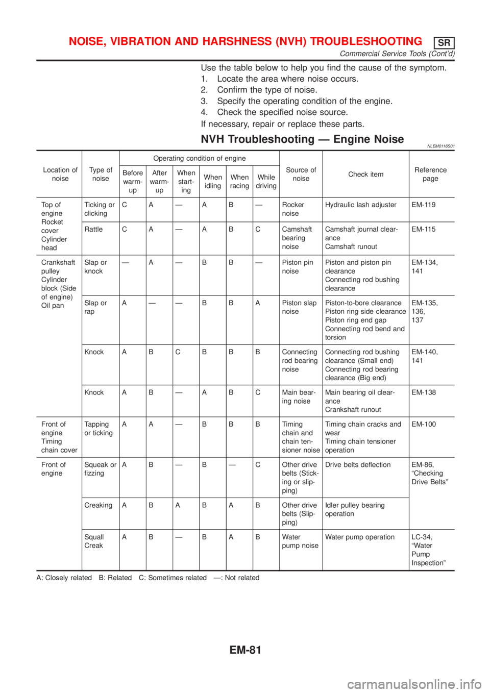
Use the table below to help you find the cause of the symptom.
1. Locate the area where noise occurs.
2. Confirm the type of noise.
3. Specify the operating condition of the engine.
4. Check the specified noise source.
If necessary, repair or replace these parts.
NVH Troubleshooting Ð Engine NoiseNLEM0116S01
Location of
noiseType of
noiseOperating condition of engine
Source of
noiseCheck itemReference
page Before
warm-
upAfter
warm-
upWhen
start-
ingWhen
idlingWhen
racingWhile
driving
To p o f
engine
Rocket
cover
Cylinder
headTicking or
clickingC A Ð A B Ð Rocker
noiseHydraulic lash adjuster EM-119
Rattle C A Ð A B C Camshaft
bearing
noiseCamshaft journal clear-
ance
Camshaft runoutEM-115
Crankshaft
pulley
Cylinder
block (Side
of engine)
Oil panSlap or
knockÐ A Ð B B Ð Piston pin
noisePiston and piston pin
clearance
Connecting rod bushing
clearanceEM-134,
141
Slap or
rapA Ð Ð B B A Piston slap
noisePiston-to-bore clearance
Piston ring side clearance
Piston ring end gap
Connecting rod bend and
torsionEM-135,
136,
137
Knock A B CB B B Connecting
rod bearing
noiseConnecting rod bushing
clearance (Small end)
Connecting rod bearing
clearance (Big end)EM-140,
141
Knock A B Ð A B C Main bear-
ing noiseMain bearing oil clear-
ance
Crankshaft runoutEM-138
Front of
engine
Timing
chain coverTapping
or tickingAAÐBBBTiming
chain and
chain ten-
sioner noiseTiming chain cracks and
wear
Timing chain tensioner
operationEM-100
Front of
engineSqueak or
fizzingA B Ð B Ð C Other drive
belts (Stick-
ing or slip-
ping)Drive belts deflection EM-86,
ªChecking
Drive Beltsº
CreakingABABABOther drive
belts (Slip-
ping)Idler pulley bearing
operation
Squall
CreakABÐBABWater
pump noiseWater pump operation LC-34,
ªWater
Pump
Inspectionº
A: Closely related B: Related C: Sometimes related Ð: Not related
NOISE, VIBRATION AND HARSHNESS (NVH) TROUBLESHOOTINGSR
Commercial Service Tools (Cont'd)
EM-81
Page 2374 of 3051
SEM931C
2. Drive out valve guide with a press [under a 20 kN (2 ton, 2.2
US ton, 2.0 Imp ton) pressure] or hammer and suitable tool.
SEM932C
3. Ream cylinder head valve guide hole.
Valve guide hole diameter
(for service parts):
Intake & Exhaust
10.175 - 10.196 mm (0.4006 - 0.4014 in)
SEM083D
4. Heat cylinder head to 110 to 130ÉC (230 to 266ÉF) and press
service valve guide into cylinder head.
Projection ªLº:
14.0 - 14.2 mm (0.551 - 0.559 in)
SEM932C
5. Ream valve guide.
Finished size:
Intake & Exhaust
6.000 - 6.018 mm (0.2362 - 0.2369 in)
SEM934C
VALVE SEATSNLEM0133S10Check valve seats for pitting at contact surface. Resurface or
replace if excessively worn.
+Before repairing valve seats, check valve and valve guide
for wear. If they are worn, replace them. Then correct valve
seat.
+Use both hands to cut uniformly.
CYLINDER HEADSR
Inspection (Cont'd)
EM-117
Page 2375 of 3051

SEM795A
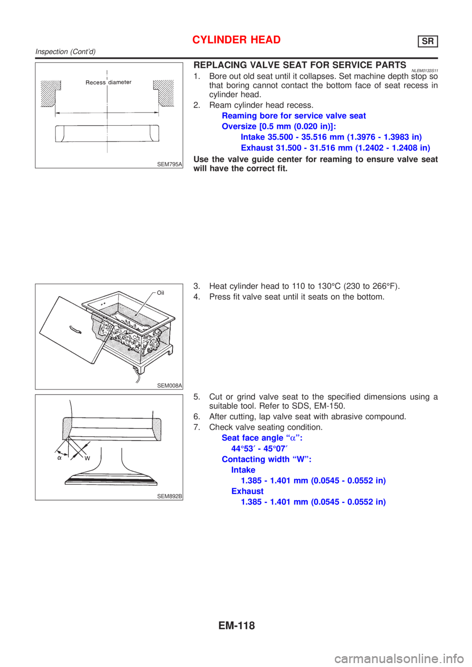
REPLACING VALVE SEAT FOR SERVICE PARTSNLEM0133S111. Bore out old seat until it collapses. Set machine depth stop so
that boring cannot contact the bottom face of seat recess in
cylinder head.
2. Ream cylinder head recess.
Reaming bore for service valve seat
Oversize [0.5 mm (0.020 in)]:
Intake 35.500 - 35.516 mm (1.3976 - 1.3983 in)
Exhaust 31.500 - 31.516 mm (1.2402 - 1.2408 in)
Use the valve guide center for reaming to ensure valve seat
will have the correct fit.
SEM008A
3. Heat cylinder head to 110 to 130ÉC (230 to 266ÉF).
4. Press fit valve seat until it seats on the bottom.
SEM892B
5. Cut or grind valve seat to the specified dimensions using a
suitable tool. Refer to SDS, EM-150.
6. After cutting, lap valve seat with abrasive compound.
7. Check valve seating condition.
Seat face angle ªaº:
44É53¢- 45É07¢
Contacting width ªWº:
Intake
1.385 - 1.401 mm (0.0545 - 0.0552 in)
Exhaust
1.385 - 1.401 mm (0.0545 - 0.0552 in)
CYLINDER HEADSR
Inspection (Cont'd)
EM-118
Page 2394 of 3051

SEM363EA
SEM011D
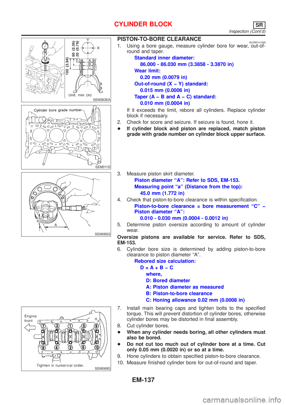
PISTON-TO-BORE CLEARANCENLEM0141S061. Using a bore gauge, measure cylinder bore for wear, out-of-
round and taper.
Standard inner diameter:
86.000 - 86.030 mm (3.3858 - 3.3870 in)
Wear limit:
0.20 mm (0.0079 in)
Out-of-round (X þ Y) standard:
0.015 mm (0.0006 in)
Taper (A þ B and A þ C) standard:
0.010 mm (0.0004 in)
If it exceeds the limit, rebore all cylinders. Replace cylinder
block if necessary.
2. Check for score and seizure. If seizure is found, hone it.
+If cylinder block and piston are replaced, match piston
grade with grade number on cylinder block upper surface.
SEM085G
3. Measure piston skirt diameter.
Piston diameter ªAº: Refer to SDS, EM-153.
Measuring point ªaº (Distance from the top):
45.0 mm (1.772 in)
4. Check that piston-to-bore clearance is within specification.
Piston-to-bore clearance = bore measurement ªCº þ
Piston diameter ªAº:
0.010 - 0.030 mm (0.0004 - 0.0012 in)
5. Determine piston oversize according to amount of cylinder
wear.
Oversize pistons are available for service. Refer to SDS,
EM-153.
6. Cylinder bore size is determined by adding piston-to-bore
clearance to piston diameter ªAº.
Rebored size calculation:
D=A+BþC
where,
D: Bored diameter
A: Piston diameter as measured
B: Piston-to-bore clearance
C: Honing allowance 0.02 mm (0.0008 in)
SEM069G
7. Install main bearing caps and tighten bolts to the specified
torque. This will prevent distortion of cylinder bores, otherwise
cylinder bores may be distorted in final assembly.
8. Cut cylinder bores.
+When any cylinder needs boring, all other cylinders must
also be bored.
+Do not cut too much out of cylinder bore at a time. Cut
only 0.05 mm (0.0020 in) or so at a time.
9. Hone cylinders to obtain specified piston-to-bore clearance.
10. Measure finished cylinder bore for out-of-round and taper.
CYLINDER BLOCKSR
Inspection (Cont'd)
EM-137