Page 438 of 2898
NAT051
4. Install idler gear bearing outer race on transmission case.
NAT052
5. Press output shaft bearing on output shaft.
SAT658D
6. Press needle bearing on bearing retainer.
SAT659D
7. Install snap ring to bearing retainer.
SAT660D
8. After packing ring grooves with petroleum jelly, carefully install
new seal rings on output shaft and bearing retainer.
REPAIR FOR COMPONENT PARTS
Output Shaft, Idler Gear, Reduction Pinion Gear and Bearing Retainer Ð 3AX10 and 3AX18 models (Cont'd)
AT-436
Page 439 of 2898
SAT661D
+Roll paper around seal rings to prevent seal rings from
spreading.
Band Servo Piston Assembly
COMPONENTSNJAT0165
SAT098K
SAT288D
DISASSEMBLYNJAT01661. Remove band servo piston snap ring.
SAT289D
2. Apply compressed air to oil hole in transmission case to
remove OD servo piston retainer and band servo piston
assembly.
+Hold band servo piston assembly with a rag or nylon
waste.
REPAIR FOR COMPONENT PARTS
Output Shaft, Idler Gear, Reduction Pinion Gear and Bearing Retainer Ð 3AX10 and 3AX18 models (Cont'd)
AT-437
Page 443 of 2898
SAT596GB
6. Install D-ring to OD servo piston.
+Apply ATF to D-ring.
SAT292DA
7. Install O-rings to OD servo piston retainer.
+Apply ATF to O-rings.
+Pay attention to the positions of the O-rings.
SAT306DA
8. Install OD servo piston to OD servo piston retainer.
SAT307DA
9. Install band servo piston assembly and 2nd servo return spring
to transmission case.
+Apply ATF to O-ring of band servo piston and transmis-
sion case.
AAT692
10. Install OD servo piston assembly to transmission case.
+Apply ATF to O-ring of band servo piston and transmis-
sion case.
REPAIR FOR COMPONENT PARTS
Band Servo Piston Assembly (Cont'd)
AT-441
Page 444 of 2898
SAT288D
11. Install band servo piston snap ring to transmission case.
Final Drive
COMPONENTS-1 3AX00, 3AX01, 3AX19, 3AX63 AND
3AX64 MODELS
NJAT0354
SAT680DA
COMPONENTS-2 3AX10 AND 3AX18 MODELSNJAT0169
SAT040K
REPAIR FOR COMPONENT PARTS
Band Servo Piston Assembly (Cont'd)
AT-442
Page 448 of 2898
SAT311G
Assembly (1)NJAT01731. Install revolution sensor onto transmission case.
Always use new sealing parts.
SAT881I
2. Install differential side oil seals on transmission case and con-
verter housing, so that ªAº and ªBº are within specifications.
SAT027K
Unit: mm (in)
AB
5.5 - 6.5 (0.217 - 0.256) þ0.5 to 0.5 (þ0.020 to 0.020)
SAT328D
3. Install parking actuator support to transmission case.
+Pay attention to direction of parking actuator support.
SAT329D
4. Install parking pawl on transmission case and fix it with park-
ing shaft.
ASSEMBLY
Assembly (1)
AT-446
Page 449 of 2898
SAT330D
5. Install return spring.
NAT059
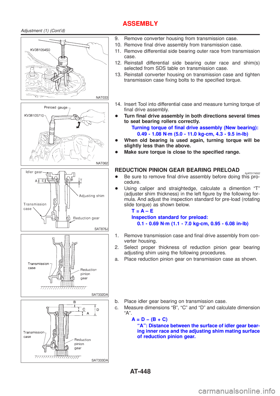
Adjustment (1)NJAT0174DIFFERENTIAL SIDE BEARING PRELOADNJAT0174S011. Install differential side bearing outer race without adjusting
shim on transmission case.
2. Install differential side bearing outer race on converter housing.
SAT027D
3. Place final drive assembly on transmission case.
4. Install transmission case on converter housing. Tighten trans-
mission case fixing boltsAandBto the specified torque.
NAT060
5. Attach dial indicator on differential case at transmission case
side.
6. Insert Tool into differential side gear from converter housing.
7. Move Tool up and down and measure dial indicator deflection.
Differential side bearing preload ªTº:
0.04 - 0.09 mm (0.0016 - 0.0035 in)
8. Select proper thickness of differential side bearing adjusting
shim(s) using SDS table as a guide.
Differential side bearing adjusting shim:
Refer to SDS, AT-478.
ASSEMBLY
Assembly (1) (Cont'd)
AT-447
Page 450 of 2898

NAT033
9. Remove converter housing from transmission case.
10. Remove final drive assembly from transmission case.
11. Remove differential side bearing outer race from transmission
case.
12. Reinstall differential side bearing outer race and shim(s)
selected from SDS table on transmission case.
13. Reinstall converter housing on transmission case and tighten
transmission case fixing bolts to the specified torque.
NAT062
14. Insert Tool into differential case and measure turning torque of
final drive assembly.
+Turn final drive assembly in both directions several times
to seat bearing rollers correctly.
Turning torque of final drive assembly (New bearing):
0.49 - 1.08 N´m (5.0 - 11.0 kg-cm, 4.3 - 9.5 in-lb)
+When old bearing is used again, turning torque will be
slightly less than the above.
+Make sure torque is close to the specified range.
SAT876J
REDUCTION PINION GEAR BEARING PRELOADNJAT0174S02+Be sure to remove final drive assembly before doing this pro-
cedure.
+Using caliper and straightedge, calculate a dimention ªTº
(adjuster shim thickness) in the left figure by the following for-
mula. And adjust the inspection standard for pre-load (rotating
slide torque) as shown below.
T=A±E
Inspection standard for preload:
0.1 - 0.69 N´m (1.1 - 7.0 kg-cm, 0.95 - 6.08 in-lb)
SAT332DA
1. Remove transmission case and final drive assembly from con-
verter housing.
2. Select proper thickness of reduction pinion gear bearing
adjusting shim using the following procedures.
a. Place reduction pinion gear on transmission case as shown.
SAT333DA
b. Place idler gear bearing on transmission case.
c. Measure dimensions ªBº, ªCº and ªDº and calculate dimension
ªAº.
A=Dþ(B+C)
ªAº: Distance between the surface of idler gear bear-
ing inner race and the adjusting shim mating surface
of reduction pinion gear.
ASSEMBLY
Adjustment (1) (Cont'd)
AT-448
Page 451 of 2898

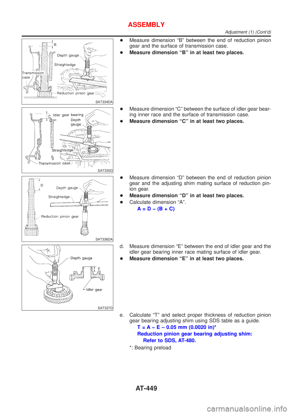
SAT334DA
+Measure dimension ªBº between the end of reduction pinion
gear and the surface of transmission case.
+Measure dimension ªBº in at least two places.
SAT335D
+Measure dimension ªCº between the surface of idler gear bear-
ing inner race and the surface of transmission case.
+Measure dimension ªCº in at least two places.
SAT336DA
+Measure dimension ªDº between the end of reduction pinion
gear and the adjusting shim mating surface of reduction pin-
ion gear.
+Measure dimension ªDº in at least two places.
+Calculate dimension ªAº.
A=Dþ(B+C)
SAT337D
d. Measure dimension ªEº between the end of idler gear and the
idler gear bearing inner race mating surface of idler gear.
+Measure dimension ªEº in at least two places.
e. Calculate ªTº and select proper thickness of reduction pinion
gear bearing adjusting shim using SDS table as a guide.
T = A þ E ± 0.05 mm (0.0020 in)*
Reduction pinion gear bearing adjusting shim:
Refer to SDS, AT-480.
*: Bearing preload
ASSEMBLY
Adjustment (1) (Cont'd)
AT-449