2001 NISSAN ALMERA transmission
[x] Cancel search: transmissionPage 868 of 2898

35 CHECK IGNITION TIMING AGAIN
Check ignition timing again. Refer to Test No. 31.
OK or NG
OK©GO TO 37.
NG©GO TO 36.
36 CHECK TIMING CHAIN INSTALLATION
Check timing chain installation. Refer to EM-28, ªInstallationº.
OK or NG
OK©GO TO 34.
NG©1. Repair the timing chain installation.
2. GO TO 32.
37 ERASE UNNECESSARY DTC
After this inspection, unnecessary DTC No. might be displayed.
Erase the stored memory in ECM and TCM (Transmission control module).
Refer to ªHow to Erase Emission-Related Diagnostic Informationº, EC-70 or EC-77 and AT-52, ªHOW TO ERASE DTCº.
OK or NG
©INSPECTION END
MODELS WITHOUT THROTTLE POSITION SWITCHNJEC1785S02Precaution:
Perform Basic Inspection without electrical or mechanical
loads applied;
+Headlamp switch is OFF,
On vehicle equipped with daytime light system, set lighting
switch to the 1st position to light only small lamps.
+Air conditioner switch is OFF,
+Rear window defogger switch is OFF,
+Steering wheel is in the straight-ahead position, etc.
1 INSPECTION START
1. Check service records for any recent repairs that may indicate a related problem, or a current need for scheduled
maintenance.
2. Open engine hood and check the following:
+Harness connectors for improper connections
+Vacuum hoses for splits, kinks and improper connections
+Wiring for improper connections, pinches and cuts
+Air cleaner clogging
+Hoses and ducts for leaks
SEF983U
©GO TO 2.
TROUBLE DIAGNOSIS Ð BASIC INSPECTIONQG
Basic Inspection/Hatchback (Cont'd)
EC-144
Page 897 of 2898

DescriptionNJEC1265The specification (SP) value indicates the tolerance of the value that is displayed in ªDATA MONITOR (SPEC)º
mode of CONSULT-II during normal operation of the Engine Control System. When the value in ªDATA MONI-
TOR (SPEC)º mode is within the SP value, the Engine Control System is confirmed OK. When the value in
ªDATA MONITOR (SPEC)º mode is NOT within the SP value, the Engine Control System may have one or
more malfunctions.
The SP value is used to detect malfunctions that may affect the Engine Control System, but will not light the
MIL.
The SP value will be displayed for the following three items:
+B/FUEL SCHDL (The fuel injection pulse width programmed into ECM prior to any learned on board cor-
rection)
+A/F ALPHA-B1 (The mean value of air-fuel ratio feedback correction factor per cycle)
+MAS A/F SE-B1 (The signal voltage of the mass air flow sensor)
Testing ConditionNJEC1266+Vehicle driven distance: More than 5,000 km (3,017 miles)
+Barometric pressure: 98.3 - 104.3 kPa (0.983 - 1.043 bar, 1.003 - 1.064 kg/cm2, 14.25 - 15.12 psi)
+Atmospheric temperature: 20 - 30ÉC (68 - 86ÉF)
+Engine coolant temperature: 75 - 95ÉC (167 - 203ÉF)
+Transmission: Warmed-up*1
+Electrical load: Not applied*2
+Engine speed: Idle
*1: For A/T or CVT models, after the engine is warmed up to normal operating temperature, drive vehicle until
ªFLUID TEMP SEº (A/T or CVT fluid temperature sensor signal) indicates less than 0.9V. For M/T models, drive
vehicle for 5 minutes after the engine is warmed up to normal operating temperature.
*2: Rear window defogger switch, air conditioner switch, lighting switch are ªOFFº. Cooling fans are not oper-
ating. Steering wheel is straight ahead.
SEF601Z
Inspection ProcedureNJEC1267NOTE:
Perform ªDATA MONITOR (SPEC)º mode in maximum scale dis-
play.
1. Perform ªBasic Inspectionº, EC-100.
2. Confirm that the testing conditions indicated above are met.
3. Select ªB/FUEL SCHDLº, ªA/F ALPHA-B1º and ªMAS A/F
SE-B1º in ªDATA MONITOR (SPEC)º mode with CONSULT-II.
4. Make sure that monitor items are within the SP value.
5. If NG, go to ªDiagnostic Procedureº, EC-174.
TROUBLE DIAGNOSIS Ð SPECIFICATION VALUEQG
Description
EC-173
Page 924 of 2898

5 DETECT MALFUNCTIONING PART
Check the following.
+Joint connector-3
+Harness connectors E74, F35
+Harness for open or short between ECM and intake air temperature sensor
+Harness for open or short between TCM (Transmission Control Module) and intake air temperature sensor
©Repair open circuit or short to ground or short to power in harness or connectors.
6 CHECK INTAKE AIR TEMPERATURE SENSOR
Refer to ªComponent Inspectionº, EC-201.
OK or NG
OK©GO TO 7.
NG©Replace intake air temperature sensor.
7 CHECK INTERMITTENT INCIDENT
Perform ªTROUBLE DIAGNOSIS FOR INTERMITTENT INCIDENTº, EC-177.
©INSPECTION END
SEF913W
Component InspectionNJEC0071INTAKE AIR TEMPERATURE SENSORNJEC0071S01Models with Intake Air Temperature Sensor on Intake
Air Duct
NJEC0071S0101Check resistance as shown in the figure.
SEF012P
Intake air temperature
ÉC (ÉF)Resistance kW
20 (68) 2.1 - 2.9
80 (176) 0.27 - 0.38
If NG, replace intake air temperature sensor.
SEC516C
Models with Intake Air Temperature Sensor in Mass Air
Flow Sensor
NJEC0071S0102Check resistance between mass air flow sensor harness connec-
tor terminals 3 and 5.
Intake air temperature
ÉC (ÉF)Resistance kW
25 (77) 1.9 - 2.1
If NG, replace intake air temperature sensor.
DTC P0110 INTAKE AIR TEMPERATURE SENSORQG
Diagnostic Procedure (Cont'd)
EC-200
Page 930 of 2898

4 DETECT MALFUNCTIONING PART
Check the following.
+Joint connector-3 (If so equipped)
+Joint connector-6 (If so equipped)
+Harness for open or short between ECM and engine coolant temperature sensor
+Harness for open or short between engine coolant temperature sensor and TCM (Transmission Control Module)
©Repair open circuit or short to ground or short to power in harness or connectors.
5 CHECK ENGINE COOLANT TEMPERATURE SENSOR
Refer to ªComponent Inspectionº, EC-206.
OK or NG
OK©GO TO 6.
NG©Replace engine coolant temperature sensor.
6 CHECK INTERMITTENT INCIDENT
Perform ªTROUBLE DIAGNOSIS FOR INTERMITTENT INCIDENTº, EC-177.
©INSPECTION END
SEF152P
SEF012P
Component InspectionNJEC0078ENGINE COOLANT TEMPERATURE SENSORNJEC0078S01Check resistance as shown in the figure.
Temperature ÉC (ÉF) Resistance kW
20 (68) 2.1 - 2.9
50 (122) 0.68 - 1.00
90 (194) 0.236 - 0.260
If NG, replace engine coolant temperature sensor.
DTC P0115 ENGINE COOLANT TEMPERATURE SENSOR
(ECTS) (CIRCUIT)
QG
Diagnostic Procedure (Cont'd)
EC-206
Page 937 of 2898

3 DETECT MALFUNCTIONING PART
Check the following.
+Joint connector-4 (If so equipped)
+Joint connector (If so equipped)
+Harness for open or short between throttle position sensor terminal 3 and ECM terminal 111
©Repair harness or connectors.
4 CHECK GROUND CIRCUIT
1. Turn ignition switch ªOFFº.
2. Check harness continuity between throttle position sensor harness connector terminal 1 and engine ground.
Refer to wiring diagram.
Continuity should exist.
3. Also check harness for short to ground and short to power.
OK or NG
OK©GO TO 6.
NG©GO TO 5.
5 DETECT MALFUNCTIONING PART
Check the following.
+Joint connector-3 (If so equipped)
+Joint connector-6 (If so equipped)
+Harness for open or short between ECM terminal 58 and throttle position sensor
+Harness for open or short between ECM terminal 58 and TCM (Transmission Control Module)
©Repair open circuit or short to ground or short to power in harness or connectors.
6 CHECK INPUT SIGNAL CIRCUIT
1. Disconnect ECM harness connector.
2. Check harness continuity between ECM terminal 92 and throttle position sensor harness connector terminal 2.
Refer to wiring diagram.
Continuity should exist.
3. Also check harness for short to ground and short to power.
OK or NG
OK©GO TO 7.
NG©Repair open circuit or short to ground or short to power in harness or connectors.
7 CHECK THROTTLE POSITION SENSOR
Refer to ªComponent Inspectionº, EC-214.
OK or NG
OK©GO TO 8.
NG©Replace throttle position sensor. To adjust it, perform ªBasic Inspectionº, EC-100.
8 CHECK INTERMITTENT INCIDENT
Perform ªTROUBLE DIAGNOSIS FOR INTERMITTENT INCIDENTº, EC-177.
©INSPECTION END
DTC P0120 THROTTLE POSITION SENSORQG
Diagnostic Procedure (Cont'd)
EC-213
Page 1107 of 2898

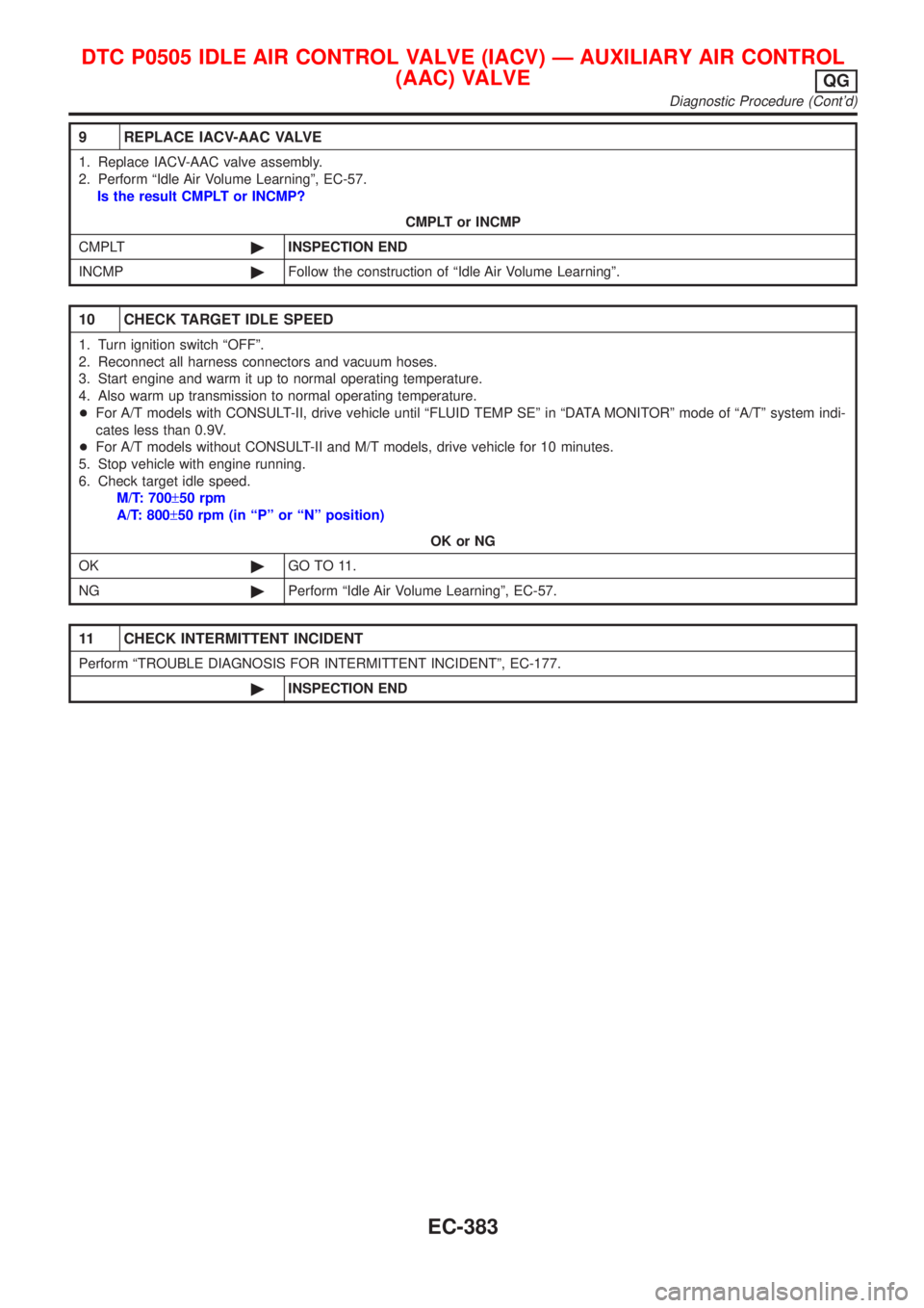
9 REPLACE IACV-AAC VALVE
1. Replace IACV-AAC valve assembly.
2. Perform ªIdle Air Volume Learningº, EC-57.
Is the result CMPLT or INCMP?
CMPLT or INCMP
CMPLT©INSPECTION END
INCMP©Follow the construction of ªIdle Air Volume Learningº.
10 CHECK TARGET IDLE SPEED
1. Turn ignition switch ªOFFº.
2. Reconnect all harness connectors and vacuum hoses.
3. Start engine and warm it up to normal operating temperature.
4. Also warm up transmission to normal operating temperature.
+For A/T models with CONSULT-II, drive vehicle until ªFLUID TEMP SEº in ªDATA MONITORº mode of ªA/Tº system indi-
cates less than 0.9V.
+For A/T models without CONSULT-II and M/T models, drive vehicle for 10 minutes.
5. Stop vehicle with engine running.
6. Check target idle speed.
M/T: 700±50 rpm
A/T: 800±50 rpm (in ªPº or ªNº position)
OK or NG
OK©GO TO 11.
NG©Perform ªIdle Air Volume Learningº, EC-57.
11 CHECK INTERMITTENT INCIDENT
Perform ªTROUBLE DIAGNOSIS FOR INTERMITTENT INCIDENTº, EC-177.
©INSPECTION END
DTC P0505 IDLE AIR CONTROL VALVE (IACV) Ð AUXILIARY AIR CONTROL
(AAC) VALVE
QG
Diagnostic Procedure (Cont'd)
EC-383
Page 1113 of 2898

4 DETECT MALFUNCTIONING PART
Check the following.
+Harness for open or short between throttle position switch and ECM
+Harness for open or short between throttle position switch and TCM (Transmission Control Module)
©Repair open circuit or short to ground or short to power in harness or connectors.
5 ADJUST THROTTLE POSITION SWITCH IDLE POSITION
Perform Basic Inspection, EC-100.
©GO TO 6.
6 CHECK CLOSED THROTTLE POSITION SWITCH
Refer to ªComponent Inspectionº, EC-389.
OK or NG
OK©GO TO 7.
NG©Replace throttle position switch.
7 CHECK THROTTLE POSITION SENSOR
Refer to ªComponent Inspectionº, EC-214.
OK or NG
OK©GO TO 8.
NG©Replace throttle position sensor.
8 CHECK INTERMITTENT INCIDENT
Perform ªTROUBLE DIAGNOSIS FOR INTERMITTENT INCIDENTº, EC-177.
©INSPECTION END
SEF197Y
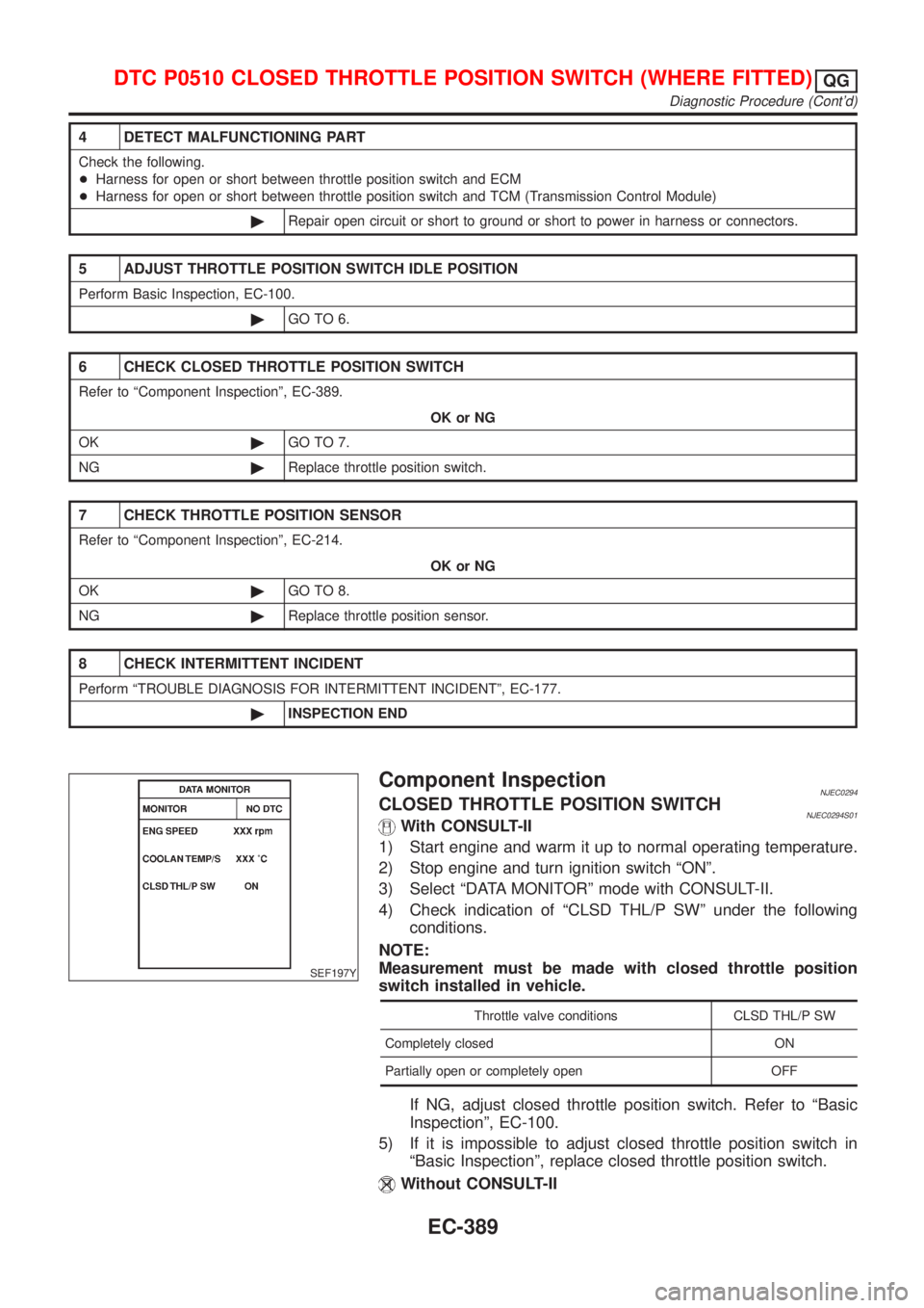
Component InspectionNJEC0294CLOSED THROTTLE POSITION SWITCHNJEC0294S01With CONSULT-II
1) Start engine and warm it up to normal operating temperature.
2) Stop engine and turn ignition switch ªONº.
3) Select ªDATA MONITORº mode with CONSULT-II.
4) Check indication of ªCLSD THL/P SWº under the following
conditions.
NOTE:
Measurement must be made with closed throttle position
switch installed in vehicle.
Throttle valve conditions CLSD THL/P SW
Completely closed ON
Partially open or completely open OFF
If NG, adjust closed throttle position switch. Refer to ªBasic
Inspectionº, EC-100.
5) If it is impossible to adjust closed throttle position switch in
ªBasic Inspectionº, replace closed throttle position switch.
Without CONSULT-II
DTC P0510 CLOSED THROTTLE POSITION SWITCH (WHERE FITTED)QG
Diagnostic Procedure (Cont'd)
EC-389
Page 1147 of 2898

Diagnostic ProcedureNJEC0347
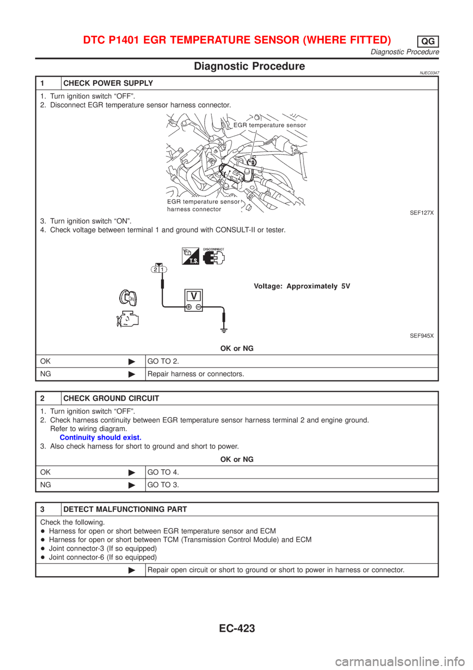
1 CHECK POWER SUPPLY
1. Turn ignition switch ªOFFº.
2. Disconnect EGR temperature sensor harness connector.
SEF127X
3. Turn ignition switch ªONº.
4. Check voltage between terminal 1 and ground with CONSULT-II or tester.
SEF945X
OK or NG
OK©GO TO 2.
NG©Repair harness or connectors.
2 CHECK GROUND CIRCUIT
1. Turn ignition switch ªOFFº.
2. Check harness continuity between EGR temperature sensor harness terminal 2 and engine ground.
Refer to wiring diagram.
Continuity should exist.
3. Also check harness for short to ground and short to power.
OK or NG
OK©GO TO 4.
NG©GO TO 3.
3 DETECT MALFUNCTIONING PART
Check the following.
+Harness for open or short between EGR temperature sensor and ECM
+Harness for open or short between TCM (Transmission Control Module) and ECM
+Joint connector-3 (If so equipped)
+Joint connector-6 (If so equipped)
©Repair open circuit or short to ground or short to power in harness or connector.
DTC P1401 EGR TEMPERATURE SENSOR (WHERE FITTED)QG
Diagnostic Procedure
EC-423