Page 1158 of 2898
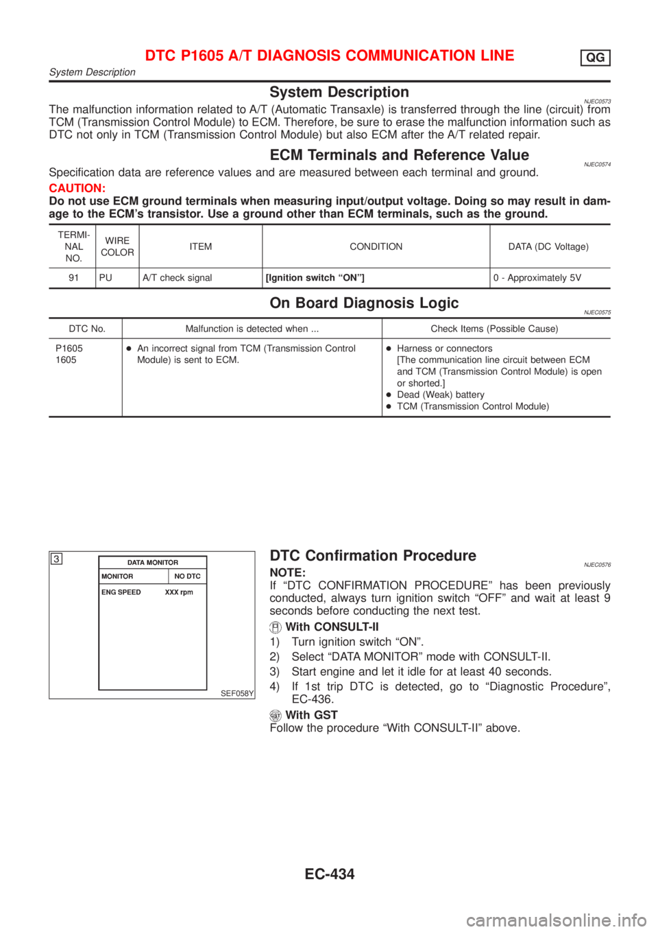
System DescriptionNJEC0573The malfunction information related to A/T (Automatic Transaxle) is transferred through the line (circuit) from
TCM (Transmission Control Module) to ECM. Therefore, be sure to erase the malfunction information such as
DTC not only in TCM (Transmission Control Module) but also ECM after the A/T related repair.
ECM Terminals and Reference ValueNJEC0574Specification data are reference values and are measured between each terminal and ground.
CAUTION:
Do not use ECM ground terminals when measuring input/output voltage. Doing so may result in dam-
age to the ECM's transistor. Use a ground other than ECM terminals, such as the ground.
TERMI-
NAL
NO.WIRE
COLORITEM CONDITION DATA (DC Voltage)
91 PU A/T check signal[Ignition switch ªONº]0 - Approximately 5V
On Board Diagnosis LogicNJEC0575
DTC No. Malfunction is detected when ... Check Items (Possible Cause)
P1605
1605+An incorrect signal from TCM (Transmission Control
Module) is sent to ECM.+Harness or connectors
[The communication line circuit between ECM
and TCM (Transmission Control Module) is open
or shorted.]
+Dead (Weak) battery
+TCM (Transmission Control Module)
SEF058Y
DTC Confirmation ProcedureNJEC0576NOTE:
If ªDTC CONFIRMATION PROCEDUREº has been previously
conducted, always turn ignition switch ªOFFº and wait at least 9
seconds before conducting the next test.
With CONSULT-II
1) Turn ignition switch ªONº.
2) Select ªDATA MONITORº mode with CONSULT-II.
3) Start engine and let it idle for at least 40 seconds.
4) If 1st trip DTC is detected, go to ªDiagnostic Procedureº,
EC-436.
With GST
Follow the procedure ªWith CONSULT-IIº above.
DTC P1605 A/T DIAGNOSIS COMMUNICATION LINEQG
System Description
EC-434
Page 1223 of 2898
7 CHECK EGR TEMPERATURE SENSOR GROUND CIRCUIT
1. Turn ignition switch ªOFFº.
2. Check harness continuity between EGR temperature sensor harness terminal 2 and engine ground.
Refer to wiring diagram.
Continuity should exist.
3. Also check harness for short to ground and short to power.
OK or NG
OK©GO TO 9.
NG©GO TO 8.
8 DETECT MALFUNCTIONING PART
Check the following.
+Harness for open or short between EGR temperature sensor and ECM
+Harness for open or short between TCM (Transmission Control Module) and ECM
+Joint connector-3 (If so equipped)
+Joint connector-6 (If so equipped)
©Repair open circuit or short to ground or short to power in harness or connector.
9 CHECK EGR TEMPERATURE SENSOR
Refer to ªComponent Inspectionº, EC-502.
OK or NG
OK©GO TO 10.
NG©Replace EGR temperature sensor.
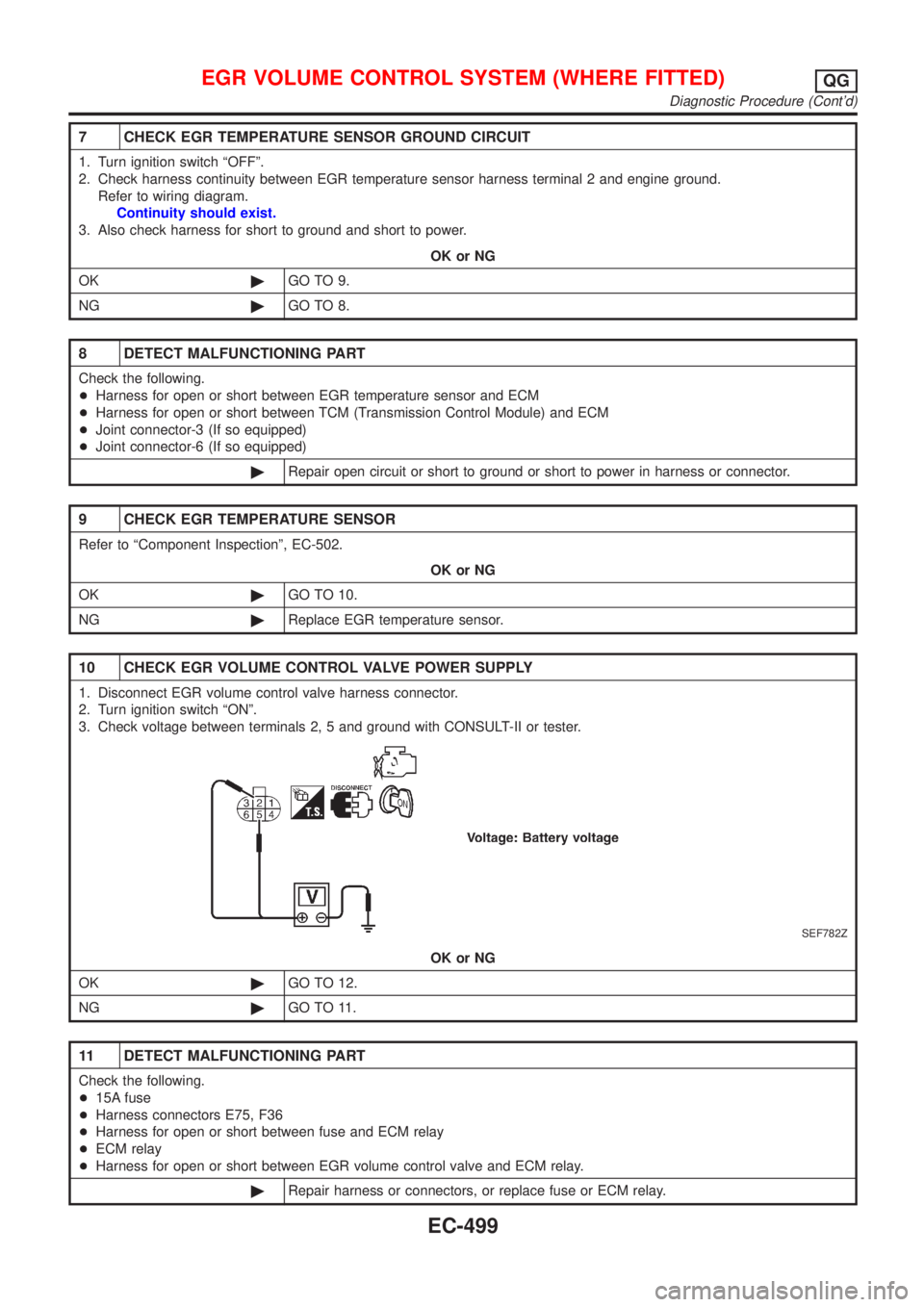
10 CHECK EGR VOLUME CONTROL VALVE POWER SUPPLY
1. Disconnect EGR volume control valve harness connector.
2. Turn ignition switch ªONº.
3. Check voltage between terminals 2, 5 and ground with CONSULT-II or tester.
SEF782Z
OK or NG
OK©GO TO 12.
NG©GO TO 11.
11 DETECT MALFUNCTIONING PART
Check the following.
+15A fuse
+Harness connectors E75, F36
+Harness for open or short between fuse and ECM relay
+ECM relay
+Harness for open or short between EGR volume control valve and ECM relay.
©Repair harness or connectors, or replace fuse or ECM relay.
EGR VOLUME CONTROL SYSTEM (WHERE FITTED)QG
Diagnostic Procedure (Cont'd)
EC-499
Page 1242 of 2898
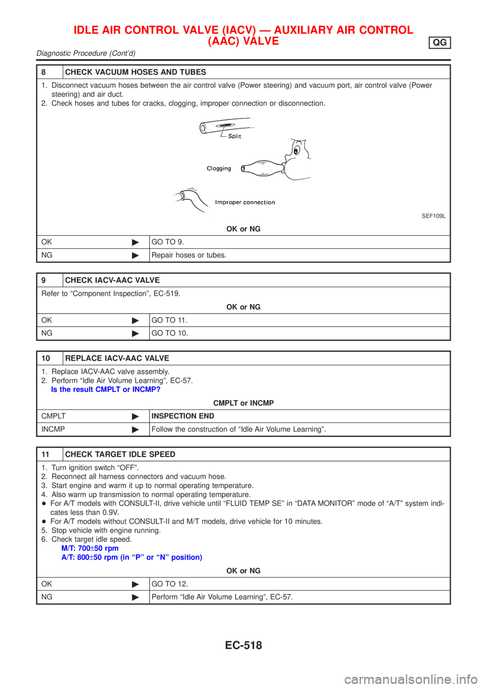
8 CHECK VACUUM HOSES AND TUBES
1. Disconnect vacuum hoses between the air control valve (Power steering) and vacuum port, air control valve (Power
steering) and air duct.
2. Check hoses and tubes for cracks, clogging, improper connection or disconnection.
SEF109L
OK or NG
OK©GO TO 9.
NG©Repair hoses or tubes.
9 CHECK IACV-AAC VALVE
Refer to ªComponent Inspectionº, EC-519.
OK or NG
OK©GO TO 11.
NG©GO TO 10.
10 REPLACE IACV-AAC VALVE
1. Replace IACV-AAC valve assembly.
2. Perform ªIdle Air Volume Learningº, EC-57.
Is the result CMPLT or INCMP?
CMPLT or INCMP
CMPLT©INSPECTION END
INCMP©Follow the construction of ªIdle Air Volume Learningº.
11 CHECK TARGET IDLE SPEED
1. Turn ignition switch ªOFFº.
2. Reconnect all harness connectors and vacuum hose.
3. Start engine and warm it up to normal operating temperature.
4. Also warm up transmission to normal operating temperature.
+For A/T models with CONSULT-II, drive vehicle until ªFLUID TEMP SEº in ªDATA MONITORº mode of ªA/Tº system indi-
cates less than 0.9V.
+For A/T models without CONSULT-II and M/T models, drive vehicle for 10 minutes.
5. Stop vehicle with engine running.
6. Check target idle speed.
M/T: 700±50 rpm
A/T: 800±50 rpm (in ªPº or ªNº position)
OK or NG
OK©GO TO 12.
NG©Perform ªIdle Air Volume Learningº, EC-57.
IDLE AIR CONTROL VALVE (IACV) Ð AUXILIARY AIR CONTROL
(AAC) VALVE
QG
Diagnostic Procedure (Cont'd)
EC-518
Page 1248 of 2898
7 DETECT MALFUNCTIONING PART
Check the following.
+Harness for open or short between throttle position switch and ECM
+Harness for open or short between throttle position switch and TCM (Transmission Control Module)
©Repair open circuit or short to ground or short to power in harness or connectors.
8 ADJUST THROTTLE POSITION SWITCH IDLE POSITION
Perform Basic Inspection, EC-100.
©GO TO 9.
9 CHECK CLOSED THROTTLE POSITION SWITCH
Refer to ªComponent Inspectionº, EC-525.
OK or NG
OK (With CONSULT-II)©GO TO 10.
OK (Without CONSULT-
II)©GO TO 11.
NG©Replace throttle position switch.
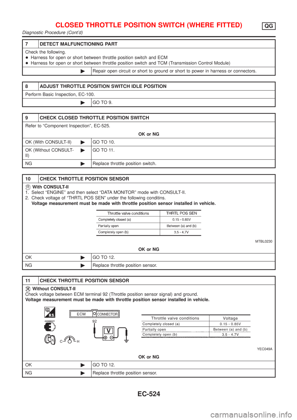
10 CHECK THROTTLE POSITION SENSOR
With CONSULT-II
1. Select ªENGINEº and then select ªDATA MONITORº mode with CONSULT-II.
2. Check voltage of ªTHRTL POS SENº under the following conditins.
Voltage measurement must be made with throttle position sensor installed in vehicle.
MTBL0230
OK or NG
OK©GO TO 12.
NG©Replace throttle position sensor.
11 CHECK THROTTLE POSITION SENSOR
Without CONSULT-II
Check voltage between ECM terminal 92 (Throttle position sensor signal) and ground.
Voltage measurement must be made with throttle position sensor installed in vehicle.
YEC049A
OK or NG
OK©GO TO 12.
NG©Replace throttle position sensor.
CLOSED THROTTLE POSITION SWITCH (WHERE FITTED)QG
Diagnostic Procedure (Cont'd)
EC-524
Page 1256 of 2898
System DescriptionNJEC1776These circuit lines are used to control the smooth shifting up and down of A/T during the hard acceleration/
deceleration.
Voltage signals are exchanged between ECM and TCM (Transmission Control Module).
A/T COMMUNICATION LINEQG
System Description
EC-532
Page 1258 of 2898
Diagnostic ProcedureNJEC1778
1 CHECK OVERALL FUNCTION
1. Start engine and warm it up to normal operating temperature.
2. Check the voltage between ECM terminals 10, 19, 54, 55, 56 and ground.
SEF791Z
OK or NG
OK©INSPECTION END
NG©GO TO 2.
2 CHECK A/T CONTROL INPUT SIGNAL CIRCUIT FOR OPEN
1. Turn ignition switch ªOFFº.
2. Disconnect ECM harness connector and TCM (Transmission Control Module) harness connector.
SEF116Y
3. Check harness continuity between the following terminals.
YEC057A
Refer to Wiring Diagram.
Continuity should exist.
OK or NG
OK©GO TO 3.
NG©Repair harness or connectors.
A/T COMMUNICATION LINEQG
Diagnostic Procedure
EC-534
Page 1300 of 2898
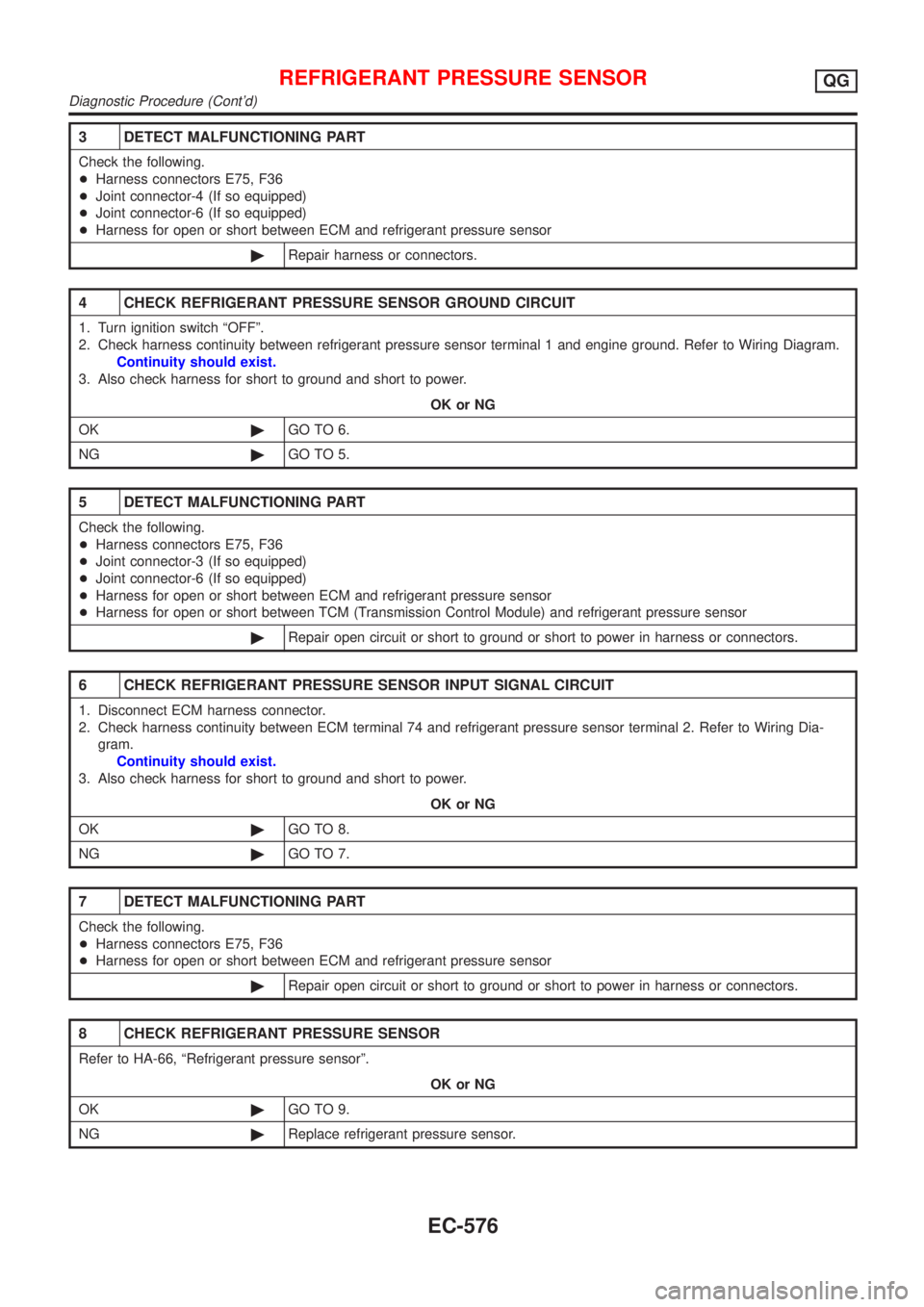
3 DETECT MALFUNCTIONING PART
Check the following.
+Harness connectors E75, F36
+Joint connector-4 (If so equipped)
+Joint connector-6 (If so equipped)
+Harness for open or short between ECM and refrigerant pressure sensor
©Repair harness or connectors.
4 CHECK REFRIGERANT PRESSURE SENSOR GROUND CIRCUIT
1. Turn ignition switch ªOFFº.
2. Check harness continuity between refrigerant pressure sensor terminal 1 and engine ground. Refer to Wiring Diagram.
Continuity should exist.
3. Also check harness for short to ground and short to power.
OK or NG
OK©GO TO 6.
NG©GO TO 5.
5 DETECT MALFUNCTIONING PART
Check the following.
+Harness connectors E75, F36
+Joint connector-3 (If so equipped)
+Joint connector-6 (If so equipped)
+Harness for open or short between ECM and refrigerant pressure sensor
+Harness for open or short between TCM (Transmission Control Module) and refrigerant pressure sensor
©Repair open circuit or short to ground or short to power in harness or connectors.
6 CHECK REFRIGERANT PRESSURE SENSOR INPUT SIGNAL CIRCUIT
1. Disconnect ECM harness connector.
2. Check harness continuity between ECM terminal 74 and refrigerant pressure sensor terminal 2. Refer to Wiring Dia-
gram.
Continuity should exist.
3. Also check harness for short to ground and short to power.
OK or NG
OK©GO TO 8.
NG©GO TO 7.
7 DETECT MALFUNCTIONING PART
Check the following.
+Harness connectors E75, F36
+Harness for open or short between ECM and refrigerant pressure sensor
©Repair open circuit or short to ground or short to power in harness or connectors.
8 CHECK REFRIGERANT PRESSURE SENSOR
Refer to HA-66, ªRefrigerant pressure sensorº.
OK or NG
OK©GO TO 9.
NG©Replace refrigerant pressure sensor.
REFRIGERANT PRESSURE SENSORQG
Diagnostic Procedure (Cont'd)
EC-576
Page 1715 of 2898
INSPECTION/VEHICLE SPEED SENSOR=NJEL0046S03
1 CHECK VEHICLE SPEED SENSOR OUTPUT
1. Remove vehicle speed sensor from transmission.
2. Check voltage between combination meter terminal 23 (with tachometer) or 37 (without tachometer) and ground while
quickly turning speed sensor pinion.
SEL657X
OK or NG
OK©Vehicle speed sensor is OK.
NG©GO TO 2.
2 CHECK VEHICLE SPEED SENSOR
Check resistance between vehicle speed sensor terminals 1 and 2.
SEL645WA
OK or NG
OK©Check the following.
+Harness between combination meter and vehicle speed sensor
+Vehicle speed sensor ground circuit
NG©Replace vehicle speed sensor.
METERS AND GAUGES
Trouble Diagnoses/Sedan (Cont'd)
EL-157