Page 1721 of 2898
MEL424F
THERMAL TRANSMITTER CHECKNJEL0047S02Check the resistance between the terminals of thermal transmitter
and body ground.
Water temperature Resistance
60ÉC (140ÉF) Approx. 170 - 210W
100ÉC (212ÉF) Approx. 47 - 53W
CEL219AA
VEHICLE SPEED SENSOR SIGNAL CHECKNJEL0047S031. Remove vehicle speed sensor from transmission.
2. Turn vehicle speed sensor pinion quickly and measure voltage
across 1 and 2.
METERS AND GAUGES
Electrical Components Inspection/Sedan (Cont'd)
EL-163
Page 1737 of 2898
INSPECTION/VEHICLE SPEED SENSOR=NJEL0448S04
1 CHECK VEHICLE SPEED SENSOR OUTPUT
1. Remove vehicle speed sensor from transmission.
2. Check voltage between combination meter terminal 29 (M152), 5 (M171) and ground while quickly turning speed sen-
sor pinion.
YEL779C
OK or NG
OK©Vehicle speed sensor is OK.
NG©GO TO 2.
2 CHECK VEHICLE SPEED SENSOR
Check resistance between vehicle speed sensor terminals 1 and 2.
SEL645WA
OK or NG
OK©Check the following.
+Harness between combination meter and vehicle speed sensor
+Vehicle speed sensor ground circuit
NG©Replace vehicle speed sensor.
METERS AND GAUGES
Trouble Diagnoses/Hatchback (Cont'd)
EL-179
Page 1741 of 2898
SEL498X
Electrical Components Inspection/Hatchback=NJEL0449FUEL LEVEL SENSOR UNIT CHECKNJEL0449S02+For removal, refer to FE-6, FE-23, ªFUEL SYSTEMº.
Check the resistance between terminals 4 and 1.
Ohmmeter
Float position mm (in)Resistance
valueW
(+) (þ)
41*1 Full 142.5 (5.61) Approx.4-6
*2 1/2 88.7 (3.492) 32 - 33
*3 Empty 11.1 (0.437) 80 - 83
*1 and *3: When float rod is in contact with stopper.
MEL424F
THERMAL TRANSMITTER CHECKNJEL0449S03Check the resistance between the terminals of thermal transmitter
and body ground.
Water temperature Resistance
65ÉC (149ÉF) Approx. 1,179 - 1,417W
91ÉC (196ÉF) Approx. 474 - 568W
CEL219AA
VEHICLE SPEED SENSOR SIGNAL CHECKNJEL0449S041. Remove vehicle speed sensor from transmission.
2. Turn vehicle speed sensor pinion quickly and measure voltage
across 1 and 2.
METERS AND GAUGES
Electrical Components Inspection/Hatchback
EL-183
Page 2039 of 2898

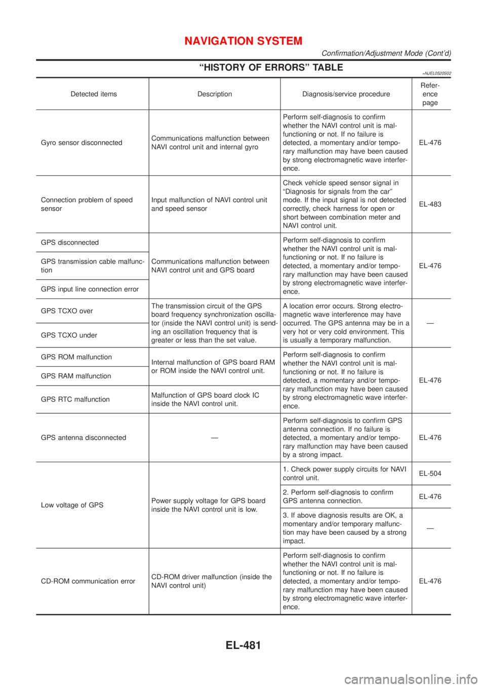
ªHISTORY OF ERRORSº TABLE=NJEL0520S02
Detected items Description Diagnosis/service procedureRefer-
ence
page
Gyro sensor disconnectedCommunications malfunction between
NAVI control unit and internal gyroPerform self-diagnosis to confirm
whether the NAVI control unit is mal-
functioning or not. If no failure is
detected, a momentary and/or tempo-
rary malfunction may have been caused
by strong electromagnetic wave interfer-
ence.EL-476
Connection problem of speed
sensorInput malfunction of NAVI control unit
and speed sensorCheck vehicle speed sensor signal in
ªDiagnosis for signals from the carº
mode. If the input signal is not detected
correctly, check harness for open or
short between combination meter and
NAVI control unit.EL-483
GPS disconnected
Communications malfunction between
NAVI control unit and GPS boardPerform self-diagnosis to confirm
whether the NAVI control unit is mal-
functioning or not. If no failure is
detected, a momentary and/or tempo-
rary malfunction may have been caused
by strong electromagnetic wave interfer-
ence.EL-476 GPS transmission cable malfunc-
tion
GPS input line connection error
GPS TCXO overThe transmission circuit of the GPS
board frequency synchronization oscilla-
tor (inside the NAVI control unit) is send-
ing an oscillation frequency that is
greater or less than the set value.A location error occurs. Strong electro-
magnetic wave interference may have
occurred. The GPS antenna may be in a
very hot or very cold environment. This
is usually a temporary malfunction.Ð
GPS TCXO under
GPS ROM malfunction
Internal malfunction of GPS board RAM
or ROM inside the NAVI control unit.Perform self-diagnosis to confirm
whether the NAVI control unit is mal-
functioning or not. If no failure is
detected, a momentary and/or tempo-
rary malfunction may have been caused
by strong electromagnetic wave interfer-
ence.EL-476 GPS RAM malfunction
GPS RTC malfunctionMalfunction of GPS board clock IC
inside the NAVI control unit.
GPS antenna disconnected ÐPerform self-diagnosis to confirm GPS
antenna connection. If no failure is
detected, a momentary and/or tempo-
rary malfunction may have been caused
by a strong impact.EL-476
Low voltage of GPSPower supply voltage for GPS board
inside the NAVI control unit is low.1. Check power supply circuits for NAVI
control unit.EL-504
2. Perform self-diagnosis to confirm
GPS antenna connection.EL-476
3. If above diagnosis results are OK, a
momentary and/or temporary malfunc-
tion may have been caused by a strong
impact.Ð
CD-ROM communication errorCD-ROM driver malfunction (inside the
NAVI control unit)Perform self-diagnosis to confirm
whether the NAVI control unit is mal-
functioning or not. If no failure is
detected, a momentary and/or tempo-
rary malfunction may have been caused
by strong electromagnetic wave interfer-
ence.EL-476
NAVIGATION SYSTEM
Confirmation/Adjustment Mode (Cont'd)
EL-481
Page 2154 of 2898
ComponentsNJEM0008
SEM391G
SEM067F
RemovalNJEM00091. Remove front RH side cover.
2. Drain engine oil.
3. Remove front exhaust tube.
Refer to FE-15, ªEXHAUST SYSTEMº.
4. Set a suitable transmission jack under transaxle and lift engine
with engine slinger.
5. Remove center member.
OIL PANQG
Components
EM-20
Page 2224 of 2898
JEM114G
3. Remove air compressor bracket.
4. Remove lower oil pan bolts.
+Loosen bolts in the reverse order of that shown in the figure.
SEM544G
5. Remove lower oil pan.
a. Insert Tool between upper oil pan and lower oil pan.
+Be careful not to damage aluminum mating surface.
+Do not insert screwdriver, or oil pan flange will be
deformed.
SEM545G
b. Slide Tool by tapping on the side of the Tool with a hammer.
c. Remove lower oil pan.
6. Remove oil strainer.
7. Remove front exhaust tube and its support.
Refer to FE-32, ªRemoval and Installationº.
JEM553G
8. Set a suitable transmission jack under transaxle and hoist
engine with engine slinger.
+Place the jack as close to the center as possible for support.
9. Remove front and rear engine mounting nuts and bolts.
10. Remove center member.
11. Remove crankshaft position sensor (TDC sensor) from oil pan.
12. Remove oil pan cover.
OIL PANYD
Removal (Cont'd)
EM-90
Page 2272 of 2898

crankshaft position sensor (TDC sensor) from the assem-
bly.
+Always pay extra attention not to damage edge of crank-
shaft position sensor (TDC sensor) or ring gear teeth.
REMOVALNJEM0069S011. Remove engine undercover, and hood for hoisting.
2. Drain coolant from both cylinder block and radiator. Refer to
LC-44, ªChanging Engine Coolantº.
3. Remove the following parts:
+Battery
+RH and LH front wheels
+RH and LH splash covers (combined with undercover)
+Auxiliary belts
+Alternator
+Alternator brackets
+Radiator and cooling fan
+Engine cover
+Air ducts and air cleaner case
LH side of engine room:
4. Disconnect all harnesses and grounds that are connected to
components on vehicle.
5. Disconnect vacuum hose on vacuum pump side.
6. Disconnect fuel feed and fuel return hoses on engine side.
+Immediately put blind plugs into the openings to prevent
fuel from flowing out.
7. Disconnect heater hose. Plug opening of hose to prevent cool-
ant from flowing out.
RH side of engine room:
8. Remove air conditioner compressor from brackets and move
it toward vehicle side. Secure compressor on vehicle side with
rope.
Vehicle underside:
9. Remove exhaust front tube.
10. Disconnect two hoses from power steering pump and plug to
stop fluid.
11. Remove M/T control rod and support rod.
12. Remove ABS wheel sensor, and temporarily hang brake cali-
per with rope on vehicle side.
13. Remove RH and LH drive shafts.
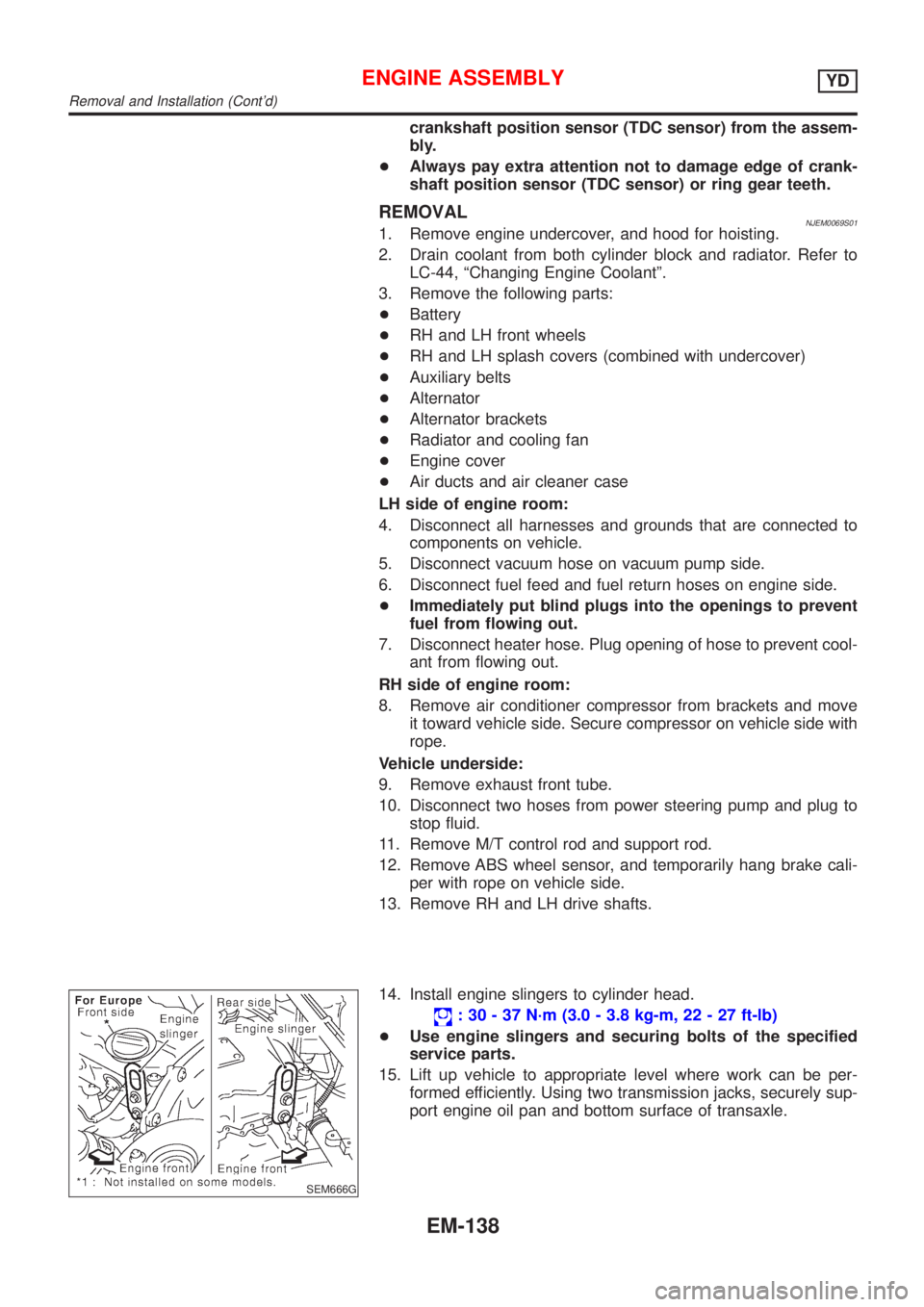
SEM666G
14. Install engine slingers to cylinder head.
: 30 - 37 N´m (3.0 - 3.8 kg-m, 22 - 27 ft-lb)
+Use engine slingers and securing bolts of the specified
service parts.
15. Lift up vehicle to appropriate level where work can be per-
formed efficiently. Using two transmission jacks, securely sup-
port engine oil pan and bottom surface of transaxle.
ENGINE ASSEMBLYYD
Removal and Installation (Cont'd)
EM-138
Page 2273 of 2898

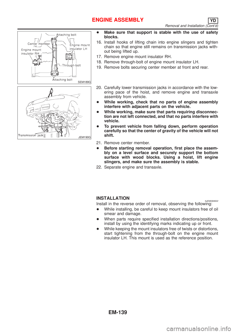
SEM189G
+Make sure that support is stable with the use of safety
blocks.
16. Install hooks of lifting chain into engine slingers and tighten
chain so that engine still remains on transmission jacks with-
out being lifted up.
17. Remove engine mount insulator RH.
18. Remove through-bolt of engine mount insulator LH.
19. Remove bolts securing center member at front and rear.
JEM190G
20. Carefully lower transmission jacks in accordance with the low-
ering pace of the hoist, and remove engine and transaxle
assembly from vehicle.
+While working, check that no parts of engine assembly
interfere with adjacent parts on the vehicle.
+While working, make sure that parts requiring disconnec-
tion are not left connected, and that no parts interfere with
vehicle.
+To prevent vehicle from falling down, perform operation
carefully so that the center of gravity of the vehicle will not
shift.
21. Remove center member.
+Before starting removal operation, first place the assem-
bly on a level surface and securely support the bottom
surface with wood blocks. Using a hoist, lift engine
slingers, and make sure the assembly is stable.
22. Separate engine and transaxle.
INSTALLATIONNJEM0069S02Install in the reverse order of removal, observing the following:
+While installing, be careful to keep mount insulators free of oil
smear and damage.
+When parts require specified installation directions/positions,
install by using the identifying marks indicating up or front.
+While keeping the mount insulators free of twists or distortions,
start tightening from the through-bolt on the engine mount
insulator LH. This mount is used as the reference position.
ENGINE ASSEMBLYYD
Removal and Installation (Cont'd)
EM-139