Page 249 of 2898
SAT014K
SAT020K
DIAGNOSTIC TROUBLE CODE (DTC) CONFIRMATION
PROCEDURE
NJAT0303S03CAUTION:
Always drive vehicle at a safe speed.
NOTE:
If ªDIAGNOSTIC TROUBLE CODE CONFIRMATION PROCE-
DUREº has been previously conducted, always turn ignition
switch ªOFFº and wait at least 5 seconds before conducting
the next test.
After the repair, perform the following procedure to confirm the
malfunction is eliminated.
With CONSULT-II
1) Turn ignition switch ªONº and select ªDATA MONITORº mode
for ªENGINEº with CONSULT-II.
2) Start engine.
3) Drive vehicle in D position and allow the transmission to shift
ª1º®ª2º (ªGEARº).
With GST
Follow the procedure ªWith CONSULT-IIº.
DTC P0750 SHIFT SOLENOID VALVE AEURO-OBD
Description (Cont'd)
AT-247
Page 255 of 2898
SAT014K
SAT020K
DIAGNOSTIC TROUBLE CODE (DTC) CONFIRMATION
PROCEDURE
NJAT0307S03CAUTION:
Always drive vehicle at a safe speed.
NOTE:
If ªDIAGNOSTIC TROUBLE CODE CONFIRMATION PROCE-
DUREº has been previously conducted, always turn ignition
switch ªOFFº and wait at least 5 seconds before conducting
the next test.
After the repair, perform the following procedure to confirm the
malfunction is eliminated.
With CONSULT-II
1) Turn ignition switch ªONº and select ªDATA MONITORº mode
for ªENGINEº with CONSULT-II.
2) Start engine.
3) Drive vehicle in D position and allow the transmission to shift
1®2®3 (ªGEARº).
With GST
Follow the procedure ªWith CONSULT-IIº.
DTC P0755 SHIFT SOLENOID VALVE BEURO-OBD
Description (Cont'd)
AT-253
Page 336 of 2898

20. Vehicle Does Not Decelerate By Engine
Brake
=NJAT0350SYMPTOM:
Vehicle does not decelerate by engine brake when shifting
from 2
2(12)to11.
1 CHECK SYMPTOM
Is 6. Vehicle Does Not Creep Backward In ªRº Position OK?
YesorNo
Ye s©Go to 15. Engine Speed Does Not Return To Idle (Light Braking D
4®D3), AT-328.
No©Go to 6. Vehicle Does Not Creep Backward In ªRº Position, AT-305.
SAT088JA
SAT360H
SAT004K
21. TCM Self-diagnosis Does Not Activate (PNP,
Overdrive Control and Throttle Position
Switches Circuit Checks)
NJAT0351SYMPTOM:
O/D OFF indicator lamp does not come on in TCM self-diag-
nostic procedure even if the lamp circuit is good.
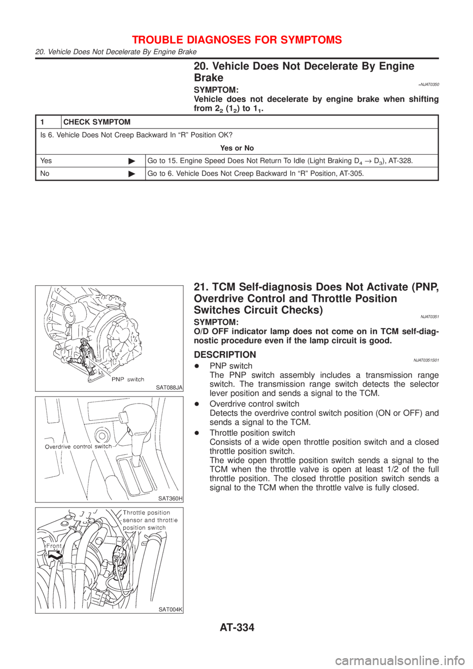
DESCRIPTIONNJAT0351S01+PNP switch
The PNP switch assembly includes a transmission range
switch. The transmission range switch detects the selector
lever position and sends a signal to the TCM.
+Overdrive control switch
Detects the overdrive control switch position (ON or OFF) and
sends a signal to the TCM.
+Throttle position switch
Consists of a wide open throttle position switch and a closed
throttle position switch.
The wide open throttle position switch sends a signal to the
TCM when the throttle valve is open at least 1/2 of the full
throttle position. The closed throttle position switch sends a
signal to the TCM when the throttle valve is fully closed.
TROUBLE DIAGNOSES FOR SYMPTOMS
20. Vehicle Does Not Decelerate By Engine Brake
AT-334
Page 353 of 2898
SAT992C
Control Valve Assembly and AccumulatorsNJAT0110REMOVALNJAT0110S011. Drain ATF from transaxle.
2. Remove oil pan and gasket.
SAT064K
3. Disconnect A/T solenoid valve harness connector.
AAT265A
4. Remove stopper ring from A/T solenoid harness terminal body.
5. Remove A/T solenoid harness by pushing terminal body into
transmission case.
AAT260A
6. Remove control valve assembly by removing fixing bolts.
Bolt length, number and location:
Bolt symbol A B C
Bolt length ª!º
40.0 mm
(1.575 in)33.0 mm
(1.299 in)43.5 mm
(1.713 in)
Number of bolts 5 6 2
+Be careful not to drop manual valve and servo release
accumulator return springs.
7. Disassemble and inspect control valve assembly if necessary.
Refer to AT-366.
ON-VEHICLE SERVICE
Control Valve Assembly and Accumulators
AT-351
Page 354 of 2898

SAT935J
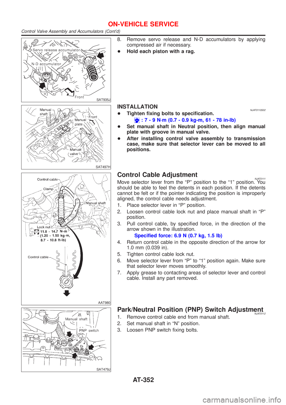
8. Remove servo release and N-D accumulators by applying
compressed air if necessary.
+Hold each piston with a rag.
SAT497H
INSTALLATIONNJAT0110S02+Tighten fixing bolts to specification.
:7-9N´m(0.7 - 0.9 kg-m, 61 - 78 in-lb)
+Set manual shaft in Neutral position, then align manual
plate with groove in manual valve.
+After installing control valve assembly to transmission
case, make sure that selector lever can be moved to all
positions.
AAT980
Control Cable AdjustmentNJAT0111Move selector lever from the ªPº position to the ª1º position. You
should be able to feel the detents in each position. If the detents
cannot be felt or if the pointer indicating the position is improperly
aligned, the control cable needs adjustment.
1. Place selector lever in ªPº position.
2. Loosen control cable lock nut and place manual shaft in ªPº
position.
3. Pull control cable, by specified force, in the direction of the
arrow shown in the illustration.
Specified force: 6.9 N (0.7 kg, 1.5 lb)
4. Return control cable in the opposite direction of the arrow for
1.0 mm (0.039 in).
5. Tighten control cable lock nut.
6. Move selector lever from ªPº to ª1º position again. Make sure
that selector lever moves smoothly.
7. Apply grease to contacting areas of selector lever and control
cable. Install any part removed.
SAT479J
Park/Neutral Position (PNP) Switch AdjustmentNJAT01121. Remove control cable end from manual shaft.
2. Set manual shaft in ªNº position.
3. Loosen PNP switch fixing bolts.
ON-VEHICLE SERVICE
Control Valve Assembly and Accumulators (Cont'd)
AT-352
Page 370 of 2898
AAT262A
b. Remove stopper ring from terminal body.
c. Push terminal body into transmission case and draw out sole-
noid harness.
SAT017D
10. Remove manual valve from control valve assembly as a pre-
caution.
SAT877J
11. Remove return spring from servo release accumulator piston.
SAT019DA
12. Remove servo release accumulator piston with compressed
air.
13. Remove O-rings from servo release accumulator piston.
SAT020D
14. Remove N-D accumulator piston and return spring with com-
pressed air.
15. Remove O-rings from N-D accumulator piston.
DISASSEMBLY
AT-368
Page 372 of 2898
SAT030D
20. Remove final drive assembly from transmission case.
NAT033
21. Remove differential side bearing outer race from transmission
case.
SAT132E
22. Remove differential side bearing adjusting shim from transmis-
sion case.
SAT840DB
23. Remove differential side bearing outer race from converter
housing.
SAT133E
24. Remove oil seal from converter housing using a screwdriver.
+Be careful not to damage case.
DISASSEMBLY
AT-370
Page 373 of 2898
SAT072D
25. Remove side oil seal from transmission case using a screw-
driver.
SAT134EA
26. Remove oil tube from converter housing.
SAT127E
27. Remove oil pump according to the following procedures.
a. Remove O-ring from input shaft.
SAT035D
b. Remove oil pump assembly from transmission case.
SAT036D
c. Remove thrust washer and bearing race from oil pump assem-
bly.
DISASSEMBLY
AT-371