2001 NISSAN ALMERA transmission
[x] Cancel search: transmissionPage 82 of 2898

SAT767B
A/T Fluid CheckNJAT0025FLUID LEAKAGE CHECKNJAT0025S011. Clean area suspected of leaking. Ð for example, mating sur-
face of converter housing and transmission case.
2. Start engine, apply foot brake, place selector lever in ªDº posi-
tion and wait a few minutes.
3. Stop engine.
SAT288G
4. Check for fresh leakage.
SAT638A
FLUID CONDITION CHECKNJAT0025S02
Fluid color Suspected problem
Dark or black with burned odor Wear of frictional material
Milky pink Water contamination Ð Road water
entering through filler tube or breather
Varnished fluid, light to dark brown
and tackyOxidation Ð Over or under filling, Ð
Overheating
FLUID LEVEL CHECKNJAT0025S03Refer to ªChecking A/T Fluidº, AT-15.
SAT647B
Stall TestNJAT0026STALL TEST PROCEDURENJAT0026S011. Check A/T fluid and engine oil levels. If necessary, add.
2. Drive vehicle for approx. 10 minutes or until fluid and oil reach
operating temperature.
ATF operating temperature:
50 - 80ÉC (122 - 176ÉF)
TROUBLE DIAGNOSIS Ð BASIC INSPECTION
A/T Fluid Check
AT-80
Page 116 of 2898

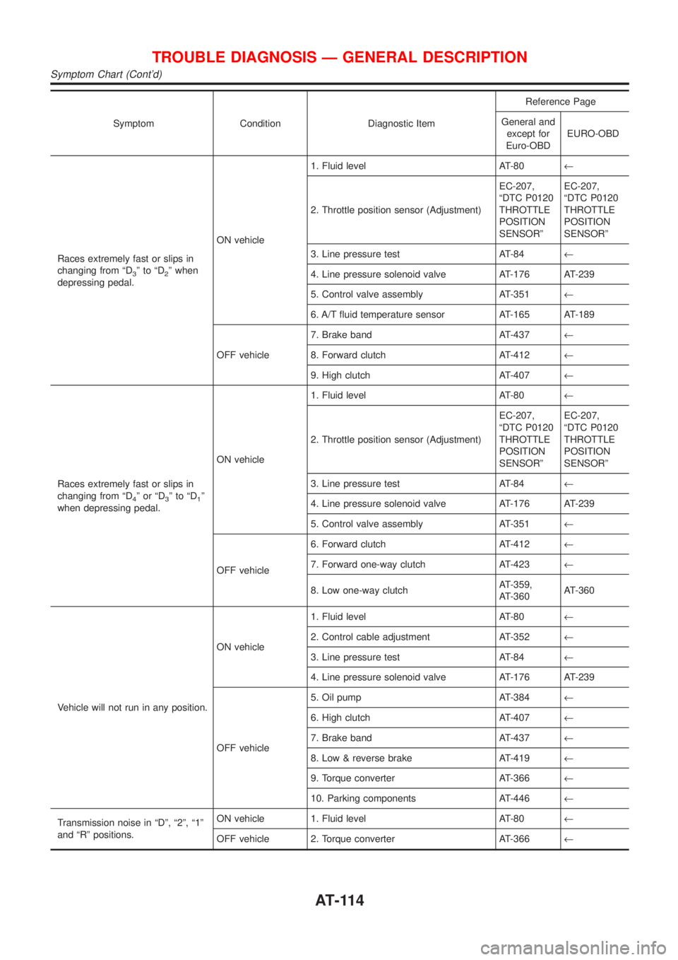
Symptom Condition Diagnostic ItemReference Page
General and
except for
Euro-OBDEURO-OBD
Races extremely fast or slips in
changing from ªD
3ºtoªD2º when
depressing pedal.ON vehicle1. Fluid level AT-80¬
2. Throttle position sensor (Adjustment)EC-207,
ªDTC P0120
THROTTLE
POSITION
SENSORºEC-207,
ªDTC P0120
THROTTLE
POSITION
SENSORº
3. Line pressure test AT-84¬
4. Line pressure solenoid valve AT-176 AT-239
5. Control valve assembly AT-351¬
6. A/T fluid temperature sensor AT-165 AT-189
OFF vehicle7. Brake band AT-437¬
8. Forward clutch AT-412¬
9. High clutch AT-407¬
Races extremely fast or slips in
changing from ªD
4ºorªD3ºtoªD1º
when depressing pedal.ON vehicle1. Fluid level AT-80¬
2. Throttle position sensor (Adjustment)EC-207,
ªDTC P0120
THROTTLE
POSITION
SENSORºEC-207,
ªDTC P0120
THROTTLE
POSITION
SENSORº
3. Line pressure test AT-84¬
4. Line pressure solenoid valve AT-176 AT-239
5. Control valve assembly AT-351¬
OFF vehicle6. Forward clutch AT-412¬
7. Forward one-way clutch AT-423¬
8. Low one-way clutchAT-359,
AT-360AT-360
Vehicle will not run in any position.ON vehicle1. Fluid level AT-80¬
2. Control cable adjustment AT-352¬
3. Line pressure test AT-84¬
4. Line pressure solenoid valve AT-176 AT-239
OFF vehicle5. Oil pump AT-384¬
6. High clutch AT-407¬
7. Brake band AT-437¬
8. Low & reverse brake AT-419¬
9. Torque converter AT-366¬
10. Parking components AT-446¬
Transmission noise in ªDº, ª2º, ª1º
and ªRº positions.ON vehicle 1. Fluid level AT-80¬
OFF vehicle 2. Torque converter AT-366¬
TROUBLE DIAGNOSIS Ð GENERAL DESCRIPTION
Symptom Chart (Cont'd)
AT-114
Page 118 of 2898

Symptom Condition Diagnostic ItemReference Page
General and
except for
Euro-OBDEURO-OBD
Large shock changing from ª1
2ºto
ª1
1º in ª1º position.ON vehicle 1. Control valve assembly AT-351¬
OFF vehicle 2. Low & reverse brake AT-419¬
Transmission overheats.ON vehicle1. Fluid level AT-80¬
2. Engine idling rpmEC-43, ªIdle
Speed and
Ignition Tim-
ingºEC-43, ªIdle
Speed and
Ignition Tim-
ingº
3. Throttle position sensor (Adjustment)EC-207,
ªDTC P0120
THROTTLE
POSITION
SENSORºEC-207,
ªDTC P0120
THROTTLE
POSITION
SENSORº
4. Line pressure test AT-84¬
5. Line pressure solenoid valve AT-176 AT-239
6. Control valve assembly AT-351¬
OFF vehicle7. Oil pump AT-384¬
8. Reverse clutch AT-403¬
9. High clutch AT-407¬
10. Brake band AT-437¬
11. Forward clutch AT-412¬
12. Overrun clutch AT-412¬
13. Low & reverse brake AT-419¬
14. Torque converter AT-366¬
ATF shoots out during operation.
White smoke emitted from exhaust
pipe during operation.ON vehicle 1. Fluid level AT-80¬
OFF vehicle2. Reverse clutch AT-403¬
3. High clutch AT-407¬
4. Brake band AT-437¬
5. Forward clutch AT-412¬
6. Overrun clutch AT-412¬
7. Low & reverse brake AT-419¬
Offensive smell at fluid charging
pipe.ON vehicle 1. Fluid level AT-80¬
OFF vehicle2. Torque converter AT-366¬
3. Oil pump AT-384¬
4. Reverse clutch AT-403¬
5. High clutch AT-407¬
6. Brake band AT-437¬
7. Forward clutch AT-412¬
8. Overrun clutch AT-412¬
9. Low & reverse brake AT-419¬
TROUBLE DIAGNOSIS Ð GENERAL DESCRIPTION
Symptom Chart (Cont'd)
AT-116
Page 185 of 2898

SAT088JA
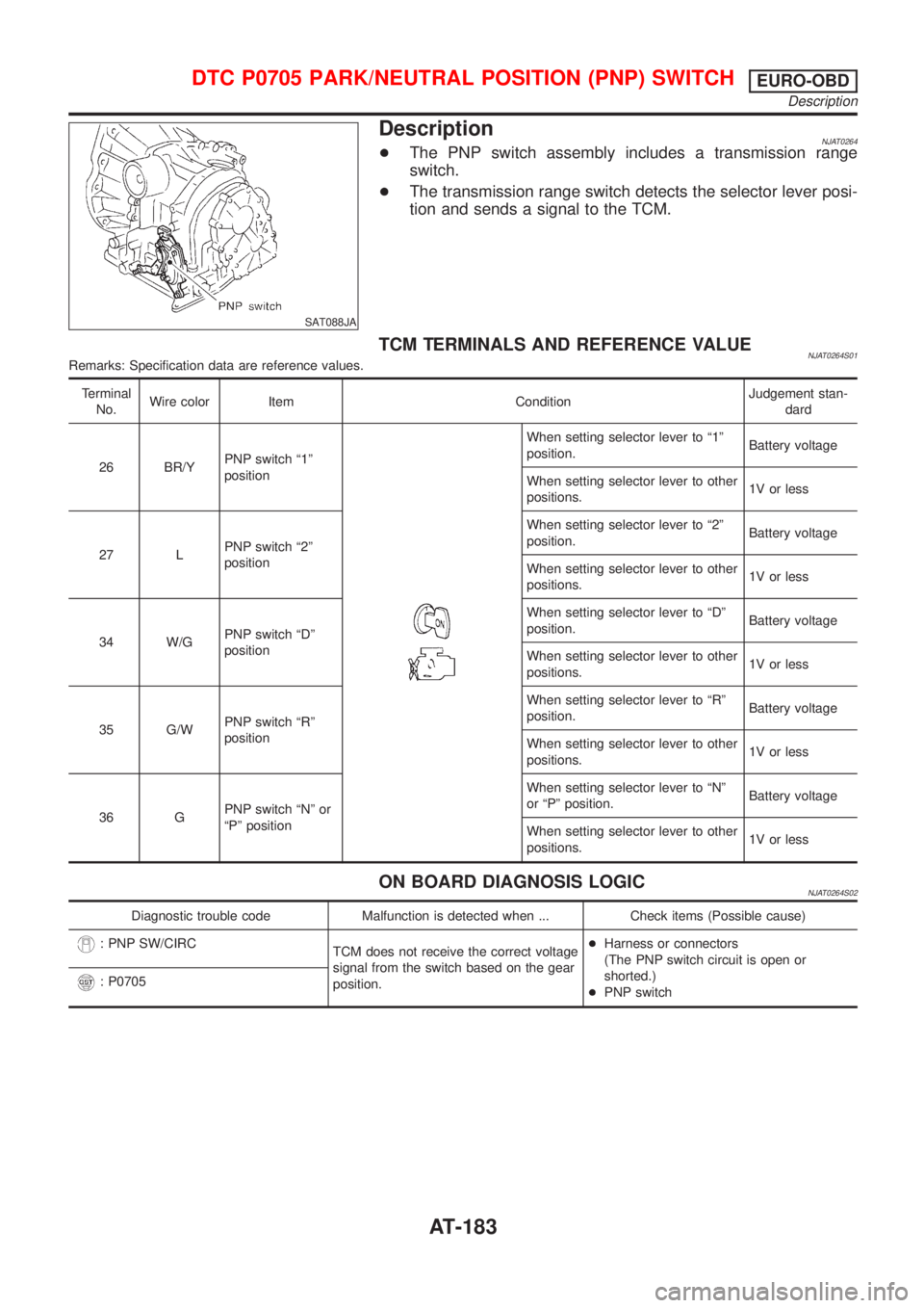
DescriptionNJAT0264+The PNP switch assembly includes a transmission range
switch.
+The transmission range switch detects the selector lever posi-
tion and sends a signal to the TCM.
TCM TERMINALS AND REFERENCE VALUENJAT0264S01Remarks: Specification data are reference values.
Terminal
No.Wire color Item ConditionJudgement stan-
dard
26 BR/YPNP switch ª1º
position
When setting selector lever to ª1º
position.Battery voltage
When setting selector lever to other
positions.1V or less
27 LPNP switch ª2º
positionWhen setting selector lever to ª2º
position.Battery voltage
When setting selector lever to other
positions.1V or less
34 W/GPNP switch ªDº
positionWhen setting selector lever to ªDº
position.Battery voltage
When setting selector lever to other
positions.1V or less
35 G/WPNP switch ªRº
positionWhen setting selector lever to ªRº
position.Battery voltage
When setting selector lever to other
positions.1V or less
36 GPNP switch ªNº or
ªPº positionWhen setting selector lever to ªNº
or ªPº position.Battery voltage
When setting selector lever to other
positions.1V or less
ON BOARD DIAGNOSIS LOGICNJAT0264S02
Diagnostic trouble code Malfunction is detected when ... Check items (Possible cause)
: PNP SW/CIRC
TCM does not receive the correct voltage
signal from the switch based on the gear
position.+Harness or connectors
(The PNP switch circuit is open or
shorted.)
+PNP switch
: P0705
DTC P0705 PARK/NEUTRAL POSITION (PNP) SWITCHEURO-OBD
Description
AT-183
Page 208 of 2898

1st trip DTC other than P0731 is shown, refer to applicable
ªTROUBLE DIAGNOSIS FOR DTCº.
6) Stop vehicle.
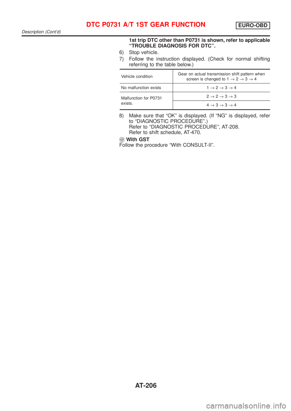
7) Follow the instruction displayed. (Check for normal shifting
referring to the table below.)
Vehicle conditionGear on actual transmission shift pattern when
screen is changed to 1®2®3®4
No malfunction exists 1®2®3®4
Malfunction for P0731
exists.2®2®3®3
4®3®3®4
8) Make sure that ªOKº is displayed. (If ªNGº is displayed, refer
to ªDIAGNOSTIC PROCEDUREº.)
Refer to ªDIAGNOSTIC PROCEDUREº, AT-208.
Refer to shift schedule, AT-470.
With GST
Follow the procedure ªWith CONSULT-IIº.
DTC P0731 A/T 1ST GEAR FUNCTIONEURO-OBD
Description (Cont'd)
AT-206
Page 214 of 2898

SAT014K
SAT971J
SAT021J
DIAGNOSTIC TROUBLE CODE (DTC) CONFIRMATION
PROCEDURE
NJAT0283S03CAUTION:
+Always drive vehicle at a safe speed.
+Be careful not to rev engine into the red zone on the
tachometer.
NOTE:
If ªDIAGNOSTIC TROUBLE CODE CONFIRMATION PROCE-
DUREº has been previously conducted, always turn ignition
switch ªOFFº and wait at least 5 seconds before conducting
the next test.
TESTING CONDITION:
Always drive vehicle on a level road to improve the accuracy
of test.
After the repair, perform the following procedure to confirm the
malfunction is eliminated.
With CONSULT-II
1) Start engine and select ªDATA MONITORº mode for ªA/Tº with
CONSULT-II.
2) Make sure that output voltage of A/T fluid temperature sensor
is within the range below.
FLUID TEMP SEN: 0.4 - 1.5V
If out of range, drive the vehicle to decrease the voltage (warm
up the fluid) or stop engine to increase the voltage (cool down
the fluid).
3) Select ª2ND GR FNCTN P0732º of ªDTC WORK SUPPORTº
mode for ªA/Tº with CONSULT-II and touch ªSTARTº.
4) Accelerate vehicle to 50 to 55 km/h (31 to 34 MPH) under the
following condition and release the accelerator pedal com-
pletely.
THROTTLE POSI: Less than 1.0/8 (at all times during step
4)
Selector lever: D position (OD ªONº)
+Check that ªGEARº shows ª3º or ª4º after releasing pedal.
5) Depress accelerator pedal to WOT (more than 7.0/8 of
ªTHROTTLE POSIº) quickly from a speed of 50 to 55 km/h (31
to 34 MPH) until ªTESTINGº changes to ªSTOP VEHICLEº or
ªCOMPLETEDº. (It will take approximately 3 seconds.)
If the check result NG appears on CONSULT-II screen, go to
ªDIAGNOSTIC PROCEDUREº, AT-215.
If ªSTOP VEHICLEº appears on CONSULT-II screen, go to
following step.
+Check that ªGEARº shows ª2º when depressing accelera-
tor pedal to WOT.
+If ªTESTINGº does not appear on CONSULT-II for a long
time, select ªSELF-DIAGNOSISº for ªENGINEº. In case a
1st trip DTC other than P0732 is shown, refer to applicable
ªTROUBLE DIAGNOSIS FOR DTCº.
6) Stop vehicle.
7) Follow the instruction displayed. (Check for normal shifting
referring to the table below.)
Vehicle conditionGear on actual transmission shift pattern when
screen is changed to 1®2®3®4
No malfunction exists 1®2®3®4
Malfunction for P0732
exists.4®3®3®4
DTC P0732 A/T 2ND GEAR FUNCTIONEURO-OBD
Description (Cont'd)
AT-212
Page 220 of 2898

SAT014K
SAT971J
SAT021J
DIAGNOSTIC TROUBLE CODE (DTC) CONFIRMATION
PROCEDURE
NJAT0287S03CAUTION:
+Always drive vehicle at a safe speed.
+Be careful not to rev engine into the red zone on the
tachometer.
NOTE:
If ªDIAGNOSTIC TROUBLE CODE CONFIRMATION PROCE-
DUREº has been previously conducted, always turn ignition
switch ªOFFº and wait at least 5 seconds before conducting
the next test.
TESTING CONDITION:
Always drive vehicle on a level road to improve the accuracy
of test.
After the repair, perform the following procedure to confirm the
malfunction is eliminated.
With CONSULT-II
1) Start engine and select ªDATA MONITORº mode for ªA/Tº with
CONSULT-II.
2) Make sure that output voltage of A/T fluid temperature sensor
is within the range below.
FLUID TEMP SEN: 0.4 - 1.5V
If out of range, drive the vehicle to decrease the voltage (warm
up the fluid) or stop engine to increase the voltage (cool down
the fluid).
3) Select ª3RD GR FNCTN P0733º of ªDTC WORK SUPPORTº
mode for ªA/Tº with CONSULT-II and touch ªSTARTº.
4) Accelerate vehicle to 70 to 85 km/h (43 to 53 MPH) under the
following condition and release the accelerator pedal com-
pletely.
THROTTLE POSI: Less than 1.0/8 (at all times during step
4)
Selector lever: D position (OD ªONº)
+Check that ªGEARº shows ª4º after releasing pedal.
5) Depress accelerator pedal steadily with 3.5/8 - 4.5/8 of
ªTHROTTLE POSIº from a speed of 70 to 85 km/h (43 to 53
MPH) until ªTESTINGº changes to ªSTOP VEHICLEº or ªCOM-
PLETEDº. (It will take approximately 3 seconds.)
If the check result NG appears on CONSULT-II screen, go to
ªDIAGNOSTIC PROCEDUREº, AT-221.
If ªSTOP VEHICLEº appears on CONSULT-II screen, go to
following step.
+Check that ªGEARº shows ª3º when depressing accelera-
tor pedal with 3.5/8 - 4.5/8 of ªTHROTTLE POSIº.
+If ªTESTINGº does not appear on CONSULT-II for a long
time, select ªSELF-DIAGNOSISº for ªENGINEº. In case a
1st trip DTC other than P0733 is shown, refer to applicable
ªTROUBLE DIAGNOSIS FOR DTCº.
6) Stop vehicle.
7) Follow the instruction displayed. (Check for normal shifting
referring to the table below.)
Vehicle conditionGear on actual transmission shift pattern when
screen is changed to 1®2®3®4
No malfunction exists. 1®2®3®4
Malfunction for P0733 exists. 1®1®4®4
DTC P0733 A/T 3RD GEAR FUNCTIONEURO-OBD
Description (Cont'd)
AT-218
Page 228 of 2898

Vehicle conditionGear on actual transmission shift pattern when
screen is changed to 1®2®3®4
No malfunction exists 1®2®3®4
Malfunction for P0734 exists. 1®2®2®1
8) Make sure that ªOKº is displayed. (If ªNGº is displayed, refer
to ªDIAGNOSTIC PROCEDUREº.)
Refer to ªDIAGNOSTIC PROCEDUREº, AT-228.
Refer to shift schedule, AT-470.
With GST
Follow the procedure ªWith CONSULT-IIº.
DTC P0734 A/T 4TH GEAR FUNCTIONEURO-OBD
Description (Cont'd)
AT-226