2001 NISSAN ALMERA engine oil
[x] Cancel search: engine oilPage 704 of 2898

NJCL0004
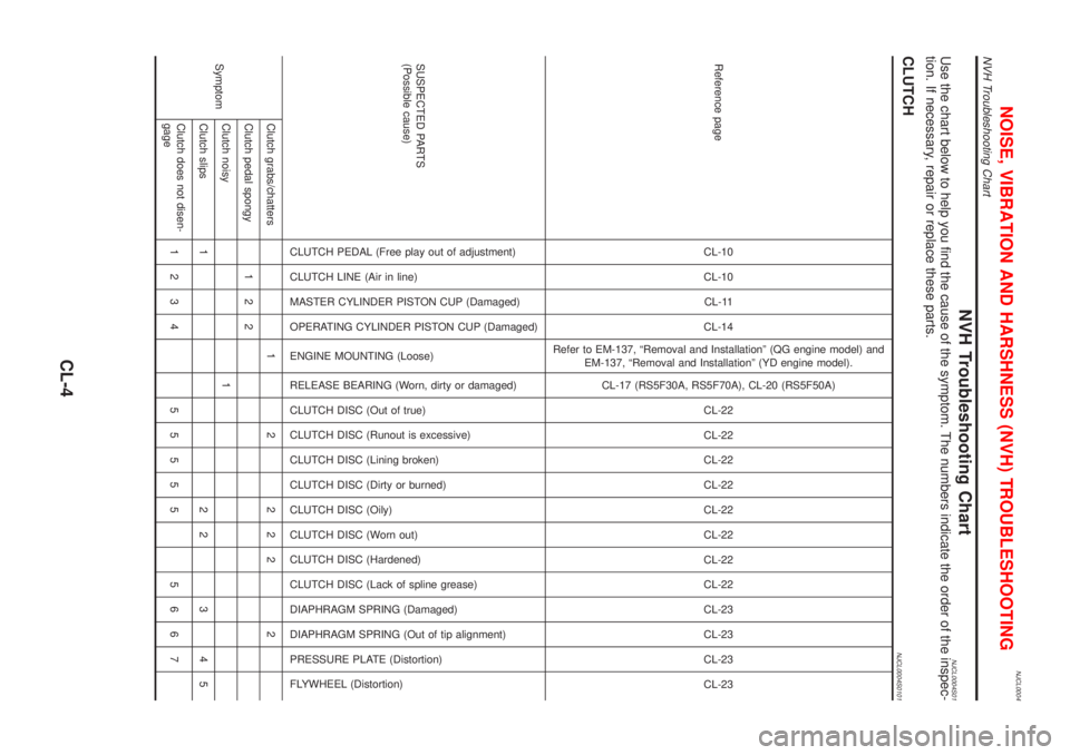
NVH Troubleshooting ChartNJCL0004S01Use the chart below to help you find the cause of the symptom. The numbers indicate the order of the inspec-
tion. If necessary, repair or replace these parts.
CLUTCHNJCL0004S0101
Reference pageCL-10
CL-10
CL-11
CL-14
Refer to EM-137, ªRemoval and Installationº (QG engine model) and
EM-137, ªRemoval and Installationº (YD engine model).
CL-17 (RS5F30A, RS5F70A), CL-20 (RS5F50A)
CL-22
CL-22
CL-22
CL-22
CL-22
CL-22
CL-22
CL-22
CL-23
CL-23
CL-23
CL-23
SUSPECTED PARTS
(Possible cause)
CLUTCH PEDAL (Free play out of adjustment)
CLUTCH LINE (Air in line)
MASTER CYLINDER PISTON CUP (Damaged)
OPERATING CYLINDER PISTON CUP (Damaged)
ENGINE MOUNTING (Loose)
RELEASE BEARING (Worn, dirty or damaged)
CLUTCH DISC (Out of true)
CLUTCH DISC (Runout is excessive)
CLUTCH DISC (Lining broken)
CLUTCH DISC (Dirty or burned)
CLUTCH DISC (Oily)
CLUTCH DISC (Worn out)
CLUTCH DISC (Hardened)
CLUTCH DISC (Lack of spline grease)
DIAPHRAGM SPRING (Damaged)
DIAPHRAGM SPRING (Out of tip alignment)
PRESSURE PLATE (Distortion)
FLYWHEEL (Distortion)
SymptomClutch grabs/chatters 1 2 2 2 2 2
Clutch pedal spongy 1 2 2
Clutch noisy 1
Clutch slips 1 2 2 3 4 5
Clutch does not disen-
gage1234 55555 5667
NOISE, VIBRATION AND HARSHNESS (NVH) TROUBLESHOOTING
NVH Troubleshooting Chart
CL-4
Page 731 of 2898

ECM Terminals and Reference Value .....................578
Wiring Diagram ........................................................579
Diagnostic Procedure - Load Signal - .....................583
Diagnostic Procedure - Heater Control Panel
(Fan Switch) - ..........................................................589
Component Inspection .............................................590
MI & DATA LINK CONNECTORS..............................591
Wiring Diagram ........................................................591
SERVICE DATA AND SPECIFICATIONS (SDS).......593
Fuel Pressure Regulator..........................................593
Idle Speed and Ignition Timing ................................593
Mass Air Flow Sensor..............................................593
Intake Air Temperature Sensor ................................593
Engine Coolant Temperature Sensor ......................593
Throttle Position Sensor ..........................................593
Heated Oxygen Sensor 1 Heater (Front) ................593
Heated Oxygen Sensor 2 Heater (Rear).................593
Fuel Tank Temperature Sensor (Where Fitted) .......594
EGR Volume Control Valve (Where Fitted) .............594
EGR Temperature Sensor (Where Fitted) ...............594
EVAP Canister Purge Volume Control Valve ..........594
IACV-AAC Valve ......................................................594
Injector .....................................................................594
Ignition Coil with Power Transistor ..........................594
Condenser ...............................................................594
Fuel Pump ...............................................................594
Crankshaft Position Sensor (POS) ..........................595
Camshaft Position Sensor (PHASE) .......................595
YD
TROUBLE DIAGNOSIS - INDEX................................596
Alphabetical & P No. Index for DTC .......................596
PRECAUTIONS...........................................................598
Supplemental Restraint System (SRS)²AIR
BAG²and²SEAT BELT PRE-TENSIONER²...........598
Engine Fuel & Emission Control System ................599
Precautions ..............................................................600
Wiring Diagrams and Trouble Diagnosis .................601
PREPARATION...........................................................602
Special Service Tools ..............................................602
ENGINE AND EMISSION CONTROL OVERALL
SYSTEM.......................................................................603
Engine Control Component Parts Location .............603
Circuit Diagram ........................................................606
System Diagram ......................................................608
System Chart ...........................................................609
ENGINE AND EMISSION BASIC CONTROL
SYSTEM DESCRIPTION.............................................610
Fuel Injection Control System .................................610
Fuel Injection Timing Control System...................... 611
Air Conditioning Cut Control ....................................612Fuel Cut Control (at no load & high engine
speed) ......................................................................612
Crankcase Ventilation System .................................613
BASIC SERVICE PROCEDURE.................................614
Injection Tube and Injection Nozzle ........................614
Electronic Control Fuel Injection Pump ...................618
Fuel Filter .................................................................625
ON BOARD DIAGNOSTIC SYSTEM
DESCRIPTION.............................................................627
DTC and MI Detection Logic ...................................627
Diagnostic Trouble Code (DTC) ..............................627
Malfunction Indicator (MI) ........................................628
CONSULT-II .............................................................632
TROUBLE DIAGNOSIS - INTRODUCTION................637
Introduction ..............................................................637
Work Flow ................................................................639
TROUBLE DIAGNOSIS - BASIC INSPECTION.........641
Basic Inspection.......................................................641
TROUBLE DIAGNOSIS - GENERAL
DESCRIPTION.............................................................646
Symptom Matrix Chart .............................................646
CONSULT-II Reference Value in Data Monitor
Mode ........................................................................656
Major Sensor Reference Graph in Data Monitor
Mode ........................................................................658
ECM Terminals and Reference Value .....................659
TROUBLE DIAGNOSIS FOR INTERMITTENT
INCIDENT.....................................................................665
Description ...............................................................665
Diagnostic Procedure ..............................................665
TROUBLE DIAGNOSIS FOR POWER SUPPLY........666
Main Power Supply and Ground Circuit ..................666
DTC P0100 MASS AIR FLOW SEN...........................673
Component Description ...........................................673
CONSULT-II Reference Value in Data Monitor
Mode ........................................................................673
ECM Terminals and Reference Value .....................673
On Board Diagnosis Logic.......................................673
DTC Confirmation Procedure ..................................673
Wiring Diagram ........................................................675
Diagnostic Procedure ..............................................677
DTC P0115 COOLANT TEMP SEN............................680
Description ...............................................................680
On Board Diagnosis Logic.......................................680
DTC Confirmation Procedure ..................................680
Wiring Diagram ........................................................682
Diagnostic Procedure ..............................................683
DTC P0120 ACCEL POS SENSOR............................685
Description ...............................................................685
CONSULT-II Reference Value in Data Monitor
Mode ........................................................................685
ECM Terminals and Reference Value .....................685
CONTENTS(Cont'd)
EC-7
Page 741 of 2898

SEF706Y
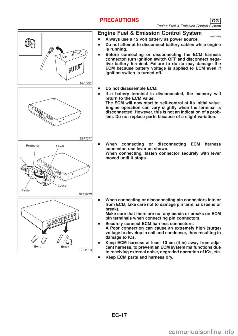
Engine Fuel & Emission Control System=NJEC0004+Always use a 12 volt battery as power source.
+Do not attempt to disconnect battery cables while engine
is running.
+Before connecting or disconnecting the ECM harness
connector, turn ignition switch OFF and disconnect nega-
tive battery terminal. Failure to do so may damage the
ECM because battery voltage is applied to ECM even if
ignition switch is turned off.
SEF707Y
+Do not disassemble ECM.
+If a battery terminal is disconnected, the memory will
return to the ECM value.
The ECM will now start to self-control at its initial value.
Engine operation can vary slightly when the terminal is
disconnected. However, this is not an indication of a prob-
lem. Do not replace parts because of a slight variation.
SEF908W
+When connecting or disconnecting ECM harness
connector, use lever as shown.
When connecting, fasten connector securely with lever
moved until it stops.
SEF291H
+When connecting or disconnecting pin connectors into or
from ECM, take care not to damage pin terminals (bend or
break).
Make sure that there are not any bends or breaks on ECM
pin terminals when connecting pin connectors.
+Securely connect ECM harness connectors.
A Poor connection can cause an extremely high (surge)
voltage to develop in coil and condenser, thus resulting in
damage to ICs.
+Keep ECM harness at least 10 cm (4 in) away from adja-
cent harness, to prevent an ECM system malfunctions due
to receiving external noise, degraded operation of ICs, etc.
+Keep ECM parts and harness dry.
PRECAUTIONSQG
Engine Fuel & Emission Control System
EC-17
Page 755 of 2898

System ChartNJEC0013
Input (Sensor) ECM Function Output (Actuator)
+Camshaft position sensor (PHASE)
+Crankshaft position sensor (POS)
+Mass air flow sensor
+Engine coolant temperature sensor
+Heated oxygen sensor 1 (front)
+Ignition switch
+Throttle position sensor
+PNP switch
+Air conditioner switch
+Knock sensor
+EGR temperature sensor*1, *4
+Fuel tank temperature sensor*1, *4
+Battery voltage
+Power steering oil pressure switch
+Vehicle speed sensor
+Intake air temperature sensor
+Heated oxygen sensor 2 (rear)*2
+TCM (Transmission Control Module)*3
+Closed throttle position switch
+Electrical load
+Refrigerant pressure sensorFuel injection & mixture ratio control Injectors
Electronic ignition system Power transistor
Idle air control system IACV-AAC valve
Intake valve timing controlIntake valve timing control sole-
noid valve
Fuel pump control Fuel pump relay
On board diagnostic systemMalfunction indicator
(On the instrument panel)
EGR control*4 EGR volume control valve*4
Heated oxygen sensor 1/2 heater (front/
rear) controlHeated oxygen sensor 1/2 heater
(front/rear)
EVAP canister purge flow controlEVAP canister purge volume con-
trol solenoid valve
Cooling fan control Cooling fan relay
Air conditioning cut control Air conditioner relay
Swirl control valve control*4Swirl control valve control sole-
noid*4
*1: These sensors are not used to control the engine system. They are used only for the on board diagnosis.
*2: Under normal conditions, this sensor is not for engine control operation.
*3: The DTC related to A/T will be sent to ECM.
*4: If so equipped
ENGINE AND EMISSION CONTROL OVERALL SYSTEMQG
System Chart
EC-31
Page 756 of 2898

Multiport Fuel Injection (MFI) System
DESCRIPTIONNJEC0014Input/Output Signal ChartNJEC0014S01
Sensor Input Signal to ECMECM func-
tionActuator
Crankshaft position sensor (POS) Engine speed
Fuel injec-
tion & mix-
ture ratio
controlInjector Camshaft position sensor (PHASE) Engine speed and cylinder number
Mass air flow sensor Amount of intake air
Engine coolant temperature sensor Engine coolant temperature
Heated oxygen sensor 1 (front) Density of oxygen in exhaust gas
Throttle position sensorThrottle position
Throttle valve idle position
PNP switch Gear position
Vehicle speed sensor Vehicle speed
Ignition switch Start signal
Air conditioner switch Air conditioner operation
Knock sensor Engine knocking condition
Electrical load Electrical load signal
Battery Battery voltage
Power steering oil pressure switch Power steering operation
Heated oxygen sensor 2 (rear)* Density of oxygen in exhaust gas
* Under normal conditions, this sensor is not for engine control operation.
Basic Multiport Fuel Injection SystemNJEC0014S02The amount of fuel injected from the fuel injector is determined by the ECM. The ECM controls the length of
time the valve remains open (injection pulse duration). The amount of fuel injected is a program value in the
ECM memory. The program value is preset by engine operating conditions. These conditions are determined
by input signals (for engine speed and intake air) from both the camshaft position sensor and the mass air
flow sensor.
Various Fuel Injection Increase/Decrease CompensationNJEC0014S03In addition, the amount of fuel injected is compensated to improve engine performance under various oper-
ating conditions as listed below.
+During warm-up
+When starting the engine
+During acceleration
+Hot-engine operation
+When selector lever is changed from ªNº to ªDº (A/T models)
+High-load, high-speed operation
+During deceleration
+During high engine speed operation
+During high vehicle speed operation (M/T models)
+Extremely high engine coolant temperature
ENGINE AND EMISSION BASIC CONTROL SYSTEM DESCRIPTIONQG
Multiport Fuel Injection (MFI) System
EC-32
Page 759 of 2898

System DescriptionNJEC0015S02
SEF742M
The ignition timing is controlled by the ECM to maintain the best air-fuel ratio for every running condition of
the engine. The ignition timing data is stored in the ECM. This data forms the map shown above.
The ECM receives information such as the injection pulse width, crankshaft position sensor signal and cam-
shaft position sensor signal. Computing this information, ignition signals are transmitted to the power transis-
tor.
e.g., N: 1,800 rpm, Tp: 1.50 msec
AÉBTDC
During the following conditions, the ignition timing is revised by the ECM according to the other data stored
in the ECM.
+At starting
+During warm-up
+At idle
+During acceleration
The knock sensor retard system is designed only for emergencies. The basic ignition timing is programmed
within the anti-knocking zone, if recommended fuel is used under dry conditions. The retard system does not
operate under normal driving conditions.
If engine knocking occurs, the knock sensor monitors the condition. The signal is transmitted to the ECM. The
ECM retards the ignition timing to eliminate the knocking condition.
Air Conditioning Cut Control
DESCRIPTIONNJEC0016Input/Output Signal ChartNJEC0016S01
Sensor Input Signal to ECMECM func-
tionActuator
Air conditioner switch Air conditioner ªONº signal
Air condi-
tioner cut
controlAir conditioner relay PNP switch Neutral position
Throttle position sensor Throttle valve opening angle
Crankshaft position sensor (POS) Engine speed
Engine coolant temperature sensor Engine coolant temperature
Ignition switch Start signal
Refrigerant pressure sensor Refrigerant pressure
Vehicle speed sensor Vehicle speed
Power steering oil pressure switch Power steering operation
System DescriptionNJEC0016S02This system improves engine operation when the air conditioner is used.
Under the following conditions, the air conditioner is turned off.
+When the accelerator pedal is fully depressed.
+When cranking the engine.
ENGINE AND EMISSION BASIC CONTROL SYSTEM DESCRIPTIONQG
Electronic Ignition (EI) System (Cont'd)
EC-35
Page 765 of 2898

If results are unsatisfactory, perform Fuel Pressure Regulator
Check, EC-41.
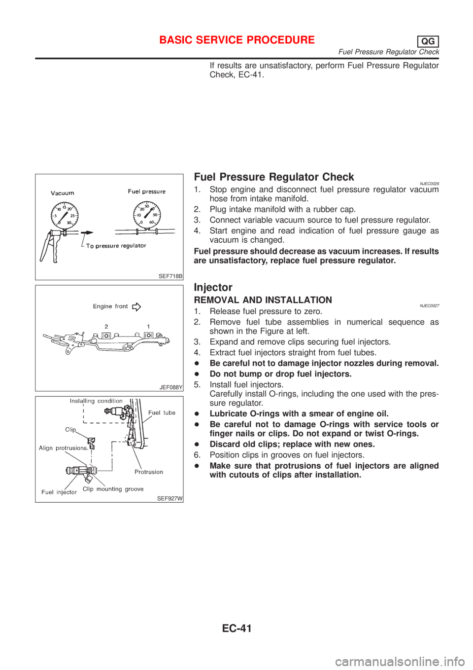
SEF718B
Fuel Pressure Regulator CheckNJEC00261. Stop engine and disconnect fuel pressure regulator vacuum
hose from intake manifold.
2. Plug intake manifold with a rubber cap.
3. Connect variable vacuum source to fuel pressure regulator.
4. Start engine and read indication of fuel pressure gauge as
vacuum is changed.
Fuel pressure should decrease as vacuum increases. If results
are unsatisfactory, replace fuel pressure regulator.
JEF088Y
SEF927W
Injector
REMOVAL AND INSTALLATIONNJEC00271. Release fuel pressure to zero.
2. Remove fuel tube assemblies in numerical sequence as
shown in the Figure at left.
3. Expand and remove clips securing fuel injectors.
4. Extract fuel injectors straight from fuel tubes.
+Be careful not to damage injector nozzles during removal.
+Do not bump or drop fuel injectors.
5. Install fuel injectors.
Carefully install O-rings, including the one used with the pres-
sure regulator.
+Lubricate O-rings with a smear of engine oil.
+Be careful not to damage O-rings with service tools or
finger nails or clips. Do not expand or twist O-rings.
+Discard old clips; replace with new ones.
6. Position clips in grooves on fuel injectors.
+Make sure that protrusions of fuel injectors are aligned
with cutouts of clips after installation.
BASIC SERVICE PROCEDUREQG
Fuel Pressure Regulator Check
EC-41
Page 768 of 2898

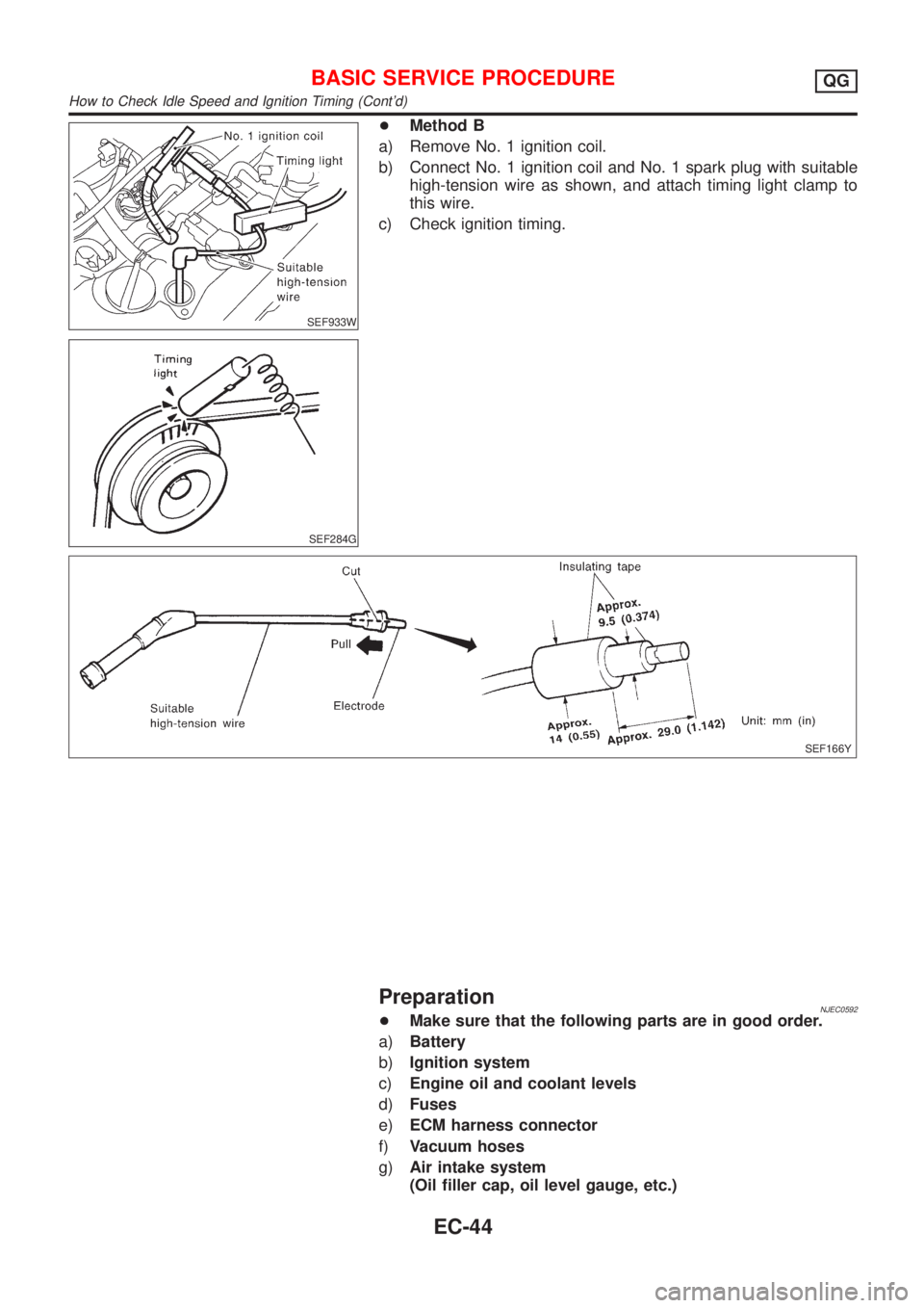
SEF933W
SEF284G
+Method B
a) Remove No. 1 ignition coil.
b) Connect No. 1 ignition coil and No. 1 spark plug with suitable
high-tension wire as shown, and attach timing light clamp to
this wire.
c) Check ignition timing.
SEF166Y
PreparationNJEC0592+Make sure that the following parts are in good order.
a)Battery
b)Ignition system
c)Engine oil and coolant levels
d)Fuses
e)ECM harness connector
f)Vacuum hoses
g)Air intake system
(Oil filler cap, oil level gauge, etc.)
BASIC SERVICE PROCEDUREQG
How to Check Idle Speed and Ignition Timing (Cont'd)
EC-44