Page 327 of 2898
13. A/T Does Not Hold Lock-up Condition=NJAT0343SYMPTOM:
A/T does not hold lock-up condition for more than 30 seconds.
1 CHECK DIAGNOSTIC RESULTS
Does self-diagnosis show damage to engine speed signal circuit after cruise test?
SAT347H
YesorNo
Ye s©Check engine speed signal circuit. Refer to AT-172 (General and except for Euro-OBD)/
AT-200 (Euro-OBD).
No©GO TO 2.
2 CHECK A/T FLUID CONDITION
1. Remove oil pan.
2. Check A/T fluid condition.
SAT171B
OK or NG
OK©GO TO 3.
NG©GO TO 5.
3 DETECT MALFUNCTIONING ITEM
1. Remove control valve assembly. Refer to AT-351.
2. Check the following items:
+Torque converter clutch control valve
+Pilot valve
+Pilot filter
OK or NG
OK©GO TO 4.
NG©Repair or replace damaged parts.
TROUBLE DIAGNOSES FOR SYMPTOMS
13. A/T Does Not Hold Lock-up Condition
AT-325
Page 331 of 2898

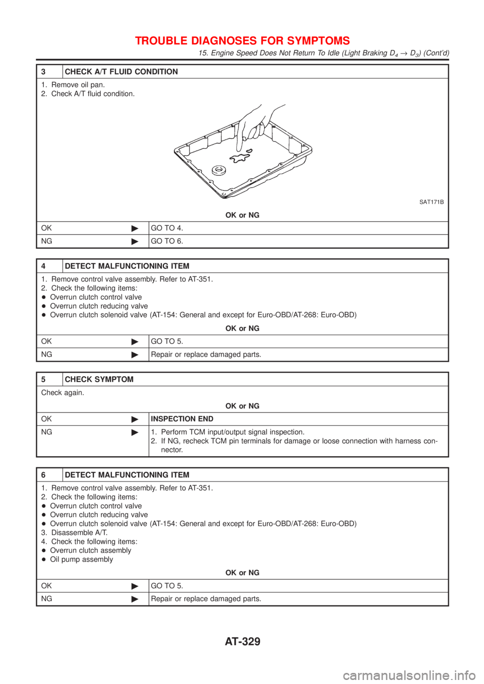
3 CHECK A/T FLUID CONDITION
1. Remove oil pan.
2. Check A/T fluid condition.
SAT171B
OK or NG
OK©GO TO 4.
NG©GO TO 6.
4 DETECT MALFUNCTIONING ITEM
1. Remove control valve assembly. Refer to AT-351.
2. Check the following items:
+Overrun clutch control valve
+Overrun clutch reducing valve
+Overrun clutch solenoid valve (AT-154: General and except for Euro-OBD/AT-268: Euro-OBD)
OK or NG
OK©GO TO 5.
NG©Repair or replace damaged parts.
5 CHECK SYMPTOM
Check again.
OK or NG
OK©INSPECTION END
NG©1. Perform TCM input/output signal inspection.
2. If NG, recheck TCM pin terminals for damage or loose connection with harness con-
nector.
6 DETECT MALFUNCTIONING ITEM
1. Remove control valve assembly. Refer to AT-351.
2. Check the following items:
+Overrun clutch control valve
+Overrun clutch reducing valve
+Overrun clutch solenoid valve (AT-154: General and except for Euro-OBD/AT-268: Euro-OBD)
3. Disassemble A/T.
4. Check the following items:
+Overrun clutch assembly
+Oil pump assembly
OK or NG
OK©GO TO 5.
NG©Repair or replace damaged parts.
TROUBLE DIAGNOSES FOR SYMPTOMS
15. Engine Speed Does Not Return To Idle (Light Braking D4®D3) (Cont'd)
AT-329
Page 356 of 2898

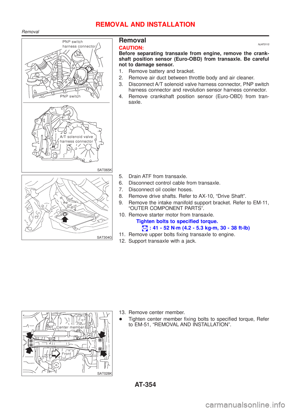
SAT065K
RemovalNJAT0115CAUTION:
Before separating transaxle from engine, remove the crank-
shaft position sensor (Euro-OBD) from transaxle. Be careful
not to damage sensor.
1. Remove battery and bracket.
2. Remove air duct between throttle body and air cleaner.
3. Disconnect A/T solenoid valve harness connector, PNP switch
harness connector and revolution sensor harness connector.
4. Remove crankshaft position sensor (Euro-OBD) from tran-
saxle.
SAT304G
5. Drain ATF from transaxle.
6. Disconnect control cable from transaxle.
7. Disconnect oil cooler hoses.
8. Remove drive shafts. Refer to AX-10, ªDrive Shaftº.
9. Remove the intake manifold support bracket. Refer to EM-11,
ªOUTER COMPONENT PARTSº.
10. Remove starter motor from transaxle.
Tighten bolts to specified torque.
: 41 - 52 N´m (4.2 - 5.3 kg-m, 30 - 38 ft-lb)
11. Remove upper bolts fixing transaxle to engine.
12. Support transaxle with a jack.
SAT028K
13. Remove center member.
+Tighten center member fixing bolts to specified torque, Refer
to EM-51, ªREMOVAL AND INSTALLATIONº.
REMOVAL AND INSTALLATION
Removal
AT-354
Page 490 of 2898
SBR686C
Precautions
PRECAUTIONSNJAX0001+When installing rubber parts, final tightening must be car-
ried out under unladen condition* with tires on ground.
*: Fuel, radiator coolant and engine oil full. Spare tire, jack,
hand tools and mats in designated positions.
+After installing removed suspension parts, check wheel
alignment and adjust if necessary.
+Use flare nut wrench when removing or installing brake
tubes.
+Always torque brake lines when installing.
Preparation
SPECIAL SERVICE TOOLSNJAX0002
Tool number
Tool nameDescription
HT72520000
Ball joint remover
NT146
Removing tie-rod outer end and lower ball joint
KV38106800
Differential side oil seal
protector
NT147
Installing drive shaft
KV38106800
COMMERCIAL SERVICE TOOLSNJAX0003
Tool name Description
1 Flare nut crowfoot
2 Torque wrench
NT360
Removing and installing each brake piping
a: 10 mm (0.39 in)
FRONT AXLE
Precautions
AX-2
Page 495 of 2898

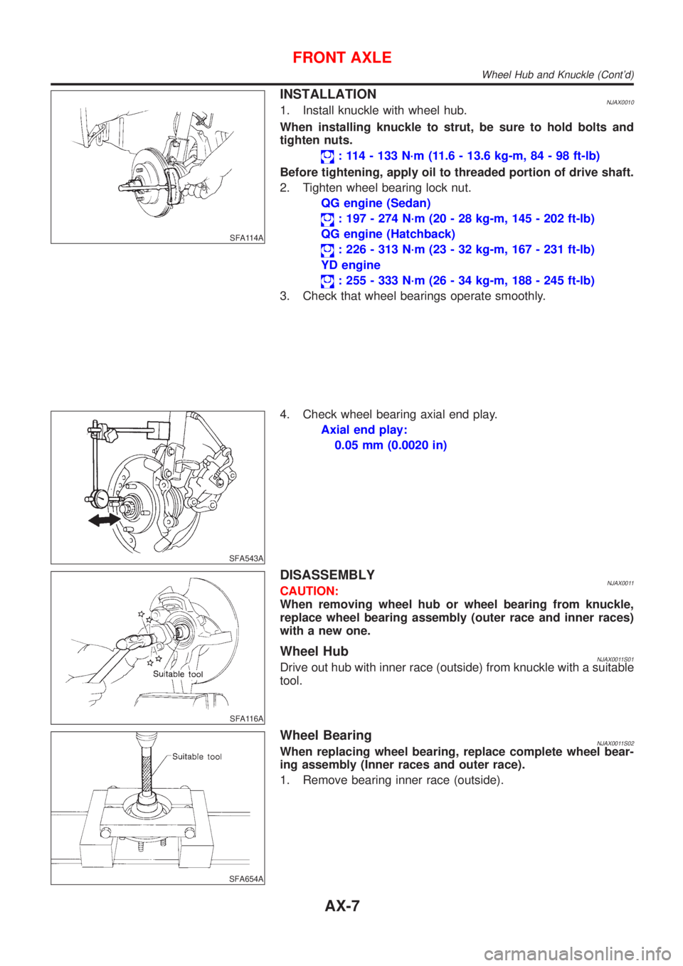
SFA114A
INSTALLATIONNJAX00101. Install knuckle with wheel hub.
When installing knuckle to strut, be sure to hold bolts and
tighten nuts.
: 114 - 133 N´m (11.6 - 13.6 kg-m, 84 - 98 ft-lb)
Before tightening, apply oil to threaded portion of drive shaft.
2. Tighten wheel bearing lock nut.
QG engine (Sedan)
: 197 - 274 N´m (20 - 28 kg-m, 145 - 202 ft-lb)
QG engine (Hatchback)
: 226 - 313 N´m (23 - 32 kg-m, 167 - 231 ft-lb)
YD engine
: 255 - 333 N´m (26 - 34 kg-m, 188 - 245 ft-lb)
3. Check that wheel bearings operate smoothly.
SFA543A
4. Check wheel bearing axial end play.
Axial end play:
0.05 mm (0.0020 in)
SFA116A
DISASSEMBLYNJAX0011CAUTION:
When removing wheel hub or wheel bearing from knuckle,
replace wheel bearing assembly (outer race and inner races)
with a new one.
Wheel HubNJAX0011S01Drive out hub with inner race (outside) from knuckle with a suitable
tool.
SFA654A
Wheel BearingNJAX0011S02When replacing wheel bearing, replace complete wheel bear-
ing assembly (Inner races and outer race).
1. Remove bearing inner race (outside).
FRONT AXLE
Wheel Hub and Knuckle (Cont'd)
AX-7
Page 510 of 2898
SBR686C
Precautions
PRECAUTIONSNJAX0022+When installing each rubber part, final tightening must be
carried out under unladen condition* with tires on ground.
*: Fuel, radiator coolant and engine oil full. Spare tire, jack,
hand tools and mats in designated positions.
+Use flare nut wrench when removing or installing brake
tubes.
+After installing removed suspension parts, check wheel
alignment.
+Do not jack up at the trailing arm and lateral link.
+Always torque brake lines when installing.
Preparation
SPECIAL SERVICE TOOLSNJAX0032
Tool number
Tool nameDescription
KV40104710
Drift
NT474
Install ABS sensor rotor
a: 76.3 mm (3.004 in) dia.
b: 67.9 mm (2.673 in) dia.
ST3072000
Drift
NT115
Install ABS sensor rotor
a: 77 mm (3.03 in) dia.
b: 55.5 mm (2.185 in) dia.
COMMERCIAL SERVICE TOOLSNJAX0024
Tool name Description
1 Flare nut crowfoot
2 Torque wrench
NT360
Removing and installing brake piping
a: 10 mm (0.39 in)
REAR AXLE
Precautions
AX-22
Page 524 of 2898

SBR451D
Checking Brake Fluid LevelNJBR0006+Check fluid level in reservoir tank. It should be between Max
and Min lines on reservoir tank.
+If fluid level is extremely low, check brake system for leaks.
+Release parking brake lever and see if brake warning lamp
goes off. If not, check brake system for leaks.
SBR389C
Checking Brake LineNJBR0007CAUTION:
If leakage occurs around joints, retighten or, if necessary,
replace damaged parts.
1. Check brake lines (tubes and hoses) for cracks, deterioration
or other damage. Replace any damaged parts.
2. Check for oil leakage by fully depressing brake pedal while
engine is running.
SBR419C
Changing Brake FluidNJBR0008CAUTION:
+Refill with new brake fluid ªDOT 4º.
+Always keep fluid level higher than minimum line on res-
ervoir tank.
+Never reuse drained brake fluid.
+Be careful not to splash brake fluid on painted areas; it
may cause paint damage. If brake fluid is splashed on
painted areas, wash it away with water immediately.
1. Clean inside of reservoir tank, and refill with new brake fluid.
2. Connect a vinyl tube to each air bleeder valve.
3. Drain brake fluid from each air bleeder valve by depressing
brake pedal while keeping reservoir level higher than minimum
line by adding new brake fluid.
4. Repeat until new brake fluid comes out of each air bleeder
valve.
Use same procedure as in bleeding hydraulic system to refill
brake fluid. Refer to ªBleeding Brake Systemº, BR-9.
Brake Burnishing ProcedureNJBR0036Burnish the brake contact surfaces according to the following pro-
cedure after refinishing or replacing drums or rotors, after replac-
ing pads or linings, or if a soft pedal occurs at very low mileage.
CAUTION:
Only perform this procedure under safe road and traffic con-
ditions. Use extreme caution.
1. Drive the vehicle on a straight smooth road at 50 km/h (31
MPH).
2. Use medium brake pedal/foot effort to bring the vehicle to a
complete stop from 50 km/h (31 MPH). Adjust brake pedal/foot
ON-VEHICLE SERVICE
Checking Brake Fluid Level
BR-8
Page 538 of 2898
SBR225B
Removal and InstallationNJBR0027CAUTION:
When installing vacuum hoses, pay attention to the following
points.
+Do not apply any oil or lubricants to vacuum hose and
check valve.
+Insert vacuum tube into vacuum hose as shown.
+Install check valve, paying attention to its direction.
InspectionNJBR0028HOSES AND CONNECTORSNJBR0028S01Check vacuum lines, connections and check valve for airtightness,
improper attachment chafing and deterioration.
SBR844B
CHECK VALVENJBR0028S02Check vacuum with a vacuum pump.
Connect to booster side Vacuum should exist.
Connect to engine side Vacuum should not exist.
VACUUM HOSE
Removal and Installation
BR-22