2001 NISSAN ALMERA engine oil
[x] Cancel search: engine oilPage 2267 of 2898
JEM175G
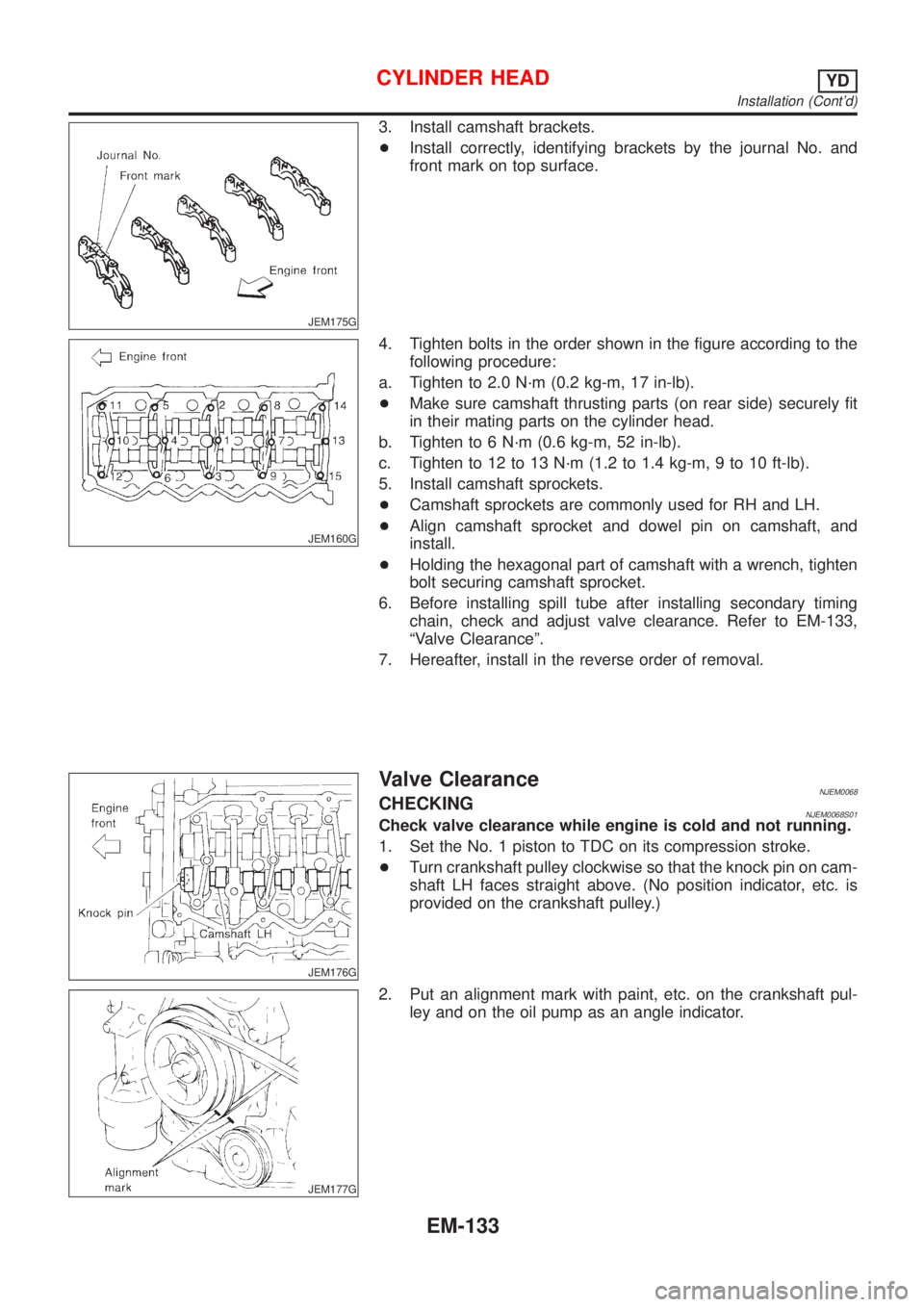
3. Install camshaft brackets.
+Install correctly, identifying brackets by the journal No. and
front mark on top surface.
JEM160G
4. Tighten bolts in the order shown in the figure according to the
following procedure:
a. Tighten to 2.0 N´m (0.2 kg-m, 17 in-lb).
+Make sure camshaft thrusting parts (on rear side) securely fit
in their mating parts on the cylinder head.
b. Tighten to 6 N´m (0.6 kg-m, 52 in-lb).
c. Tighten to 12 to 13 N´m (1.2 to 1.4 kg-m, 9 to 10 ft-lb).
5. Install camshaft sprockets.
+Camshaft sprockets are commonly used for RH and LH.
+Align camshaft sprocket and dowel pin on camshaft, and
install.
+Holding the hexagonal part of camshaft with a wrench, tighten
bolt securing camshaft sprocket.
6. Before installing spill tube after installing secondary timing
chain, check and adjust valve clearance. Refer to EM-133,
ªValve Clearanceº.
7. Hereafter, install in the reverse order of removal.
JEM176G
Valve ClearanceNJEM0068CHECKINGNJEM0068S01Check valve clearance while engine is cold and not running.
1. Set the No. 1 piston to TDC on its compression stroke.
+Turn crankshaft pulley clockwise so that the knock pin on cam-
shaft LH faces straight above. (No position indicator, etc. is
provided on the crankshaft pulley.)
JEM177G
2. Put an alignment mark with paint, etc. on the crankshaft pul-
ley and on the oil pump as an angle indicator.
CYLINDER HEADYD
Installation (Cont'd)
EM-133
Page 2269 of 2898
SEM498G
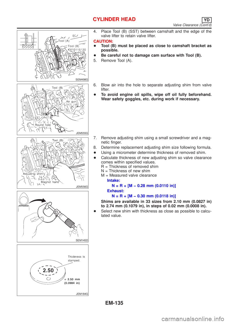
4. Place Tool (B) (SST) between camshaft and the edge of the
valve lifter to retain valve lifter.
CAUTION:
+Tool (B) must be placed as close to camshaft bracket as
possible.
+Be careful not to damage cam surface with Tool (B).
5. Remove Tool (A).
JEM555G
6. Blow air into the hole to separate adjusting shim from valve
lifter.
+To avoid engine oil spills, wipe off oil fully beforehand.
Wear safety goggles, etc. during work if necessary.
JEM556G
SEM145D
JEM184G
7. Remove adjusting shim using a small screwdriver and a mag-
netic finger.
8. Determine replacement adjusting shim size following formula.
+Using a micrometer determine thickness of removed shim.
+Calculate thickness of new adjusting shim so valve clearance
comes within specified values.
R = Thickness of removed shim
N = Thickness of new shim
M = Measured valve clearance
Intake:
N=R+[Mþ0.28 mm (0.0110 in)]
Exhaust:
N=R+[Mþ0.30 mm (0.0118 in)]
Shims are available in 33 sizes from 2.10 mm (0.0827 in)
to 2.74 mm (0.1079 in), in steps of 0.02 mm (0.0008 in).
+Select new shim with thickness as close as possible to calcu-
lated value.
CYLINDER HEADYD
Valve Clearance (Cont'd)
EM-135
Page 2272 of 2898
crankshaft position sensor (TDC sensor) from the assem-
bly.
+Always pay extra attention not to damage edge of crank-
shaft position sensor (TDC sensor) or ring gear teeth.
REMOVALNJEM0069S011. Remove engine undercover, and hood for hoisting.
2. Drain coolant from both cylinder block and radiator. Refer to
LC-44, ªChanging Engine Coolantº.
3. Remove the following parts:
+Battery
+RH and LH front wheels
+RH and LH splash covers (combined with undercover)
+Auxiliary belts
+Alternator
+Alternator brackets
+Radiator and cooling fan
+Engine cover
+Air ducts and air cleaner case
LH side of engine room:
4. Disconnect all harnesses and grounds that are connected to
components on vehicle.
5. Disconnect vacuum hose on vacuum pump side.
6. Disconnect fuel feed and fuel return hoses on engine side.
+Immediately put blind plugs into the openings to prevent
fuel from flowing out.
7. Disconnect heater hose. Plug opening of hose to prevent cool-
ant from flowing out.
RH side of engine room:
8. Remove air conditioner compressor from brackets and move
it toward vehicle side. Secure compressor on vehicle side with
rope.
Vehicle underside:
9. Remove exhaust front tube.
10. Disconnect two hoses from power steering pump and plug to
stop fluid.
11. Remove M/T control rod and support rod.
12. Remove ABS wheel sensor, and temporarily hang brake cali-
per with rope on vehicle side.
13. Remove RH and LH drive shafts.
SEM666G
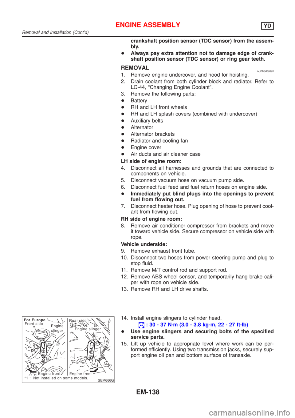
14. Install engine slingers to cylinder head.
: 30 - 37 N´m (3.0 - 3.8 kg-m, 22 - 27 ft-lb)
+Use engine slingers and securing bolts of the specified
service parts.
15. Lift up vehicle to appropriate level where work can be per-
formed efficiently. Using two transmission jacks, securely sup-
port engine oil pan and bottom surface of transaxle.
ENGINE ASSEMBLYYD
Removal and Installation (Cont'd)
EM-138
Page 2273 of 2898
SEM189G
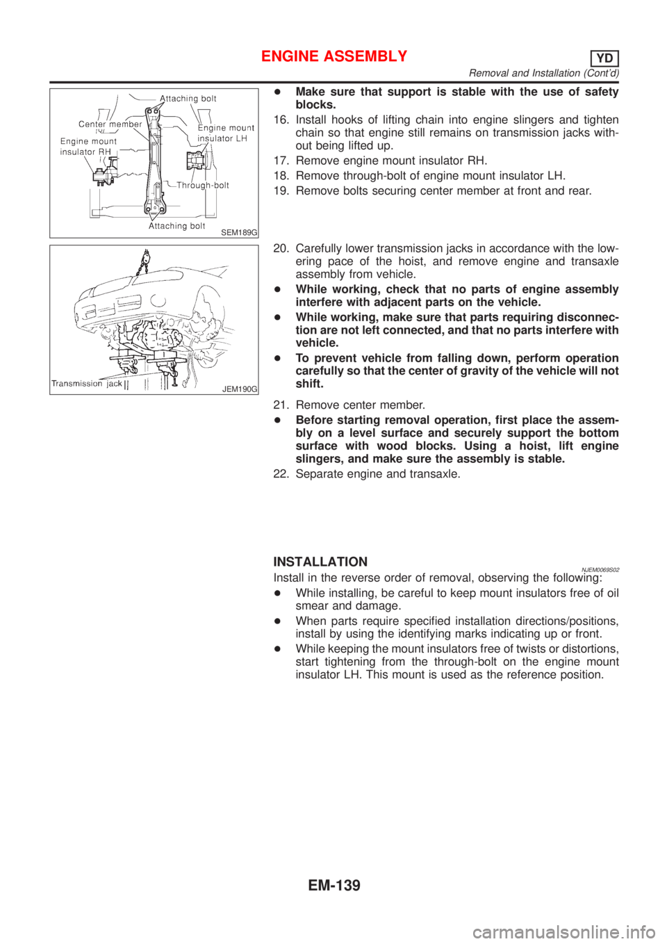
+Make sure that support is stable with the use of safety
blocks.
16. Install hooks of lifting chain into engine slingers and tighten
chain so that engine still remains on transmission jacks with-
out being lifted up.
17. Remove engine mount insulator RH.
18. Remove through-bolt of engine mount insulator LH.
19. Remove bolts securing center member at front and rear.
JEM190G
20. Carefully lower transmission jacks in accordance with the low-
ering pace of the hoist, and remove engine and transaxle
assembly from vehicle.
+While working, check that no parts of engine assembly
interfere with adjacent parts on the vehicle.
+While working, make sure that parts requiring disconnec-
tion are not left connected, and that no parts interfere with
vehicle.
+To prevent vehicle from falling down, perform operation
carefully so that the center of gravity of the vehicle will not
shift.
21. Remove center member.
+Before starting removal operation, first place the assem-
bly on a level surface and securely support the bottom
surface with wood blocks. Using a hoist, lift engine
slingers, and make sure the assembly is stable.
22. Separate engine and transaxle.
INSTALLATIONNJEM0069S02Install in the reverse order of removal, observing the following:
+While installing, be careful to keep mount insulators free of oil
smear and damage.
+When parts require specified installation directions/positions,
install by using the identifying marks indicating up or front.
+While keeping the mount insulators free of twists or distortions,
start tightening from the through-bolt on the engine mount
insulator LH. This mount is used as the reference position.
ENGINE ASSEMBLYYD
Removal and Installation (Cont'd)
EM-139
Page 2275 of 2898
Removal and InstallationNJEM0071CAUTION:
+When installing bearings, pistons, or other sliding parts,
lubricate contacting surfaces with new engine oil.
+Place removed parts such as bearings and bearing caps
in their proper order and direction.
+When installing connecting rod nuts, and main bearing
cap bolts, apply new engine oil to threads and seating
surfaces.
+Do not allow any magnetic materials to contact the signal
plate of flywheel.
+Do not remove the signal plate at back.
+Do not place the signal plate side facing under.
+Handle with care so as not to damage the signal plate
[especially four places on protrusions for signal of crank
position sensor (TDC sensor)].
DisassemblyNJEM0072PISTON AND CRANKSHAFTNJEM0072S011. Remove engine. Refer to ªENGINE ASSEMBLYº, ªRemoval
and Installationº, EM-137.
2. Place engine on a work stand.
a. Remove flywheel.
+Hold ring gear with ring gear stopper (KV10105630,
KV10105610). Then, loosen securing bolts with TORX socket
(size: Q8 E20, Commercial Service Tool) and remove them.
As an alternative method, hold the crankshaft pulley with a
pulley holder (SST) to remove the flywheel.
JEM192G
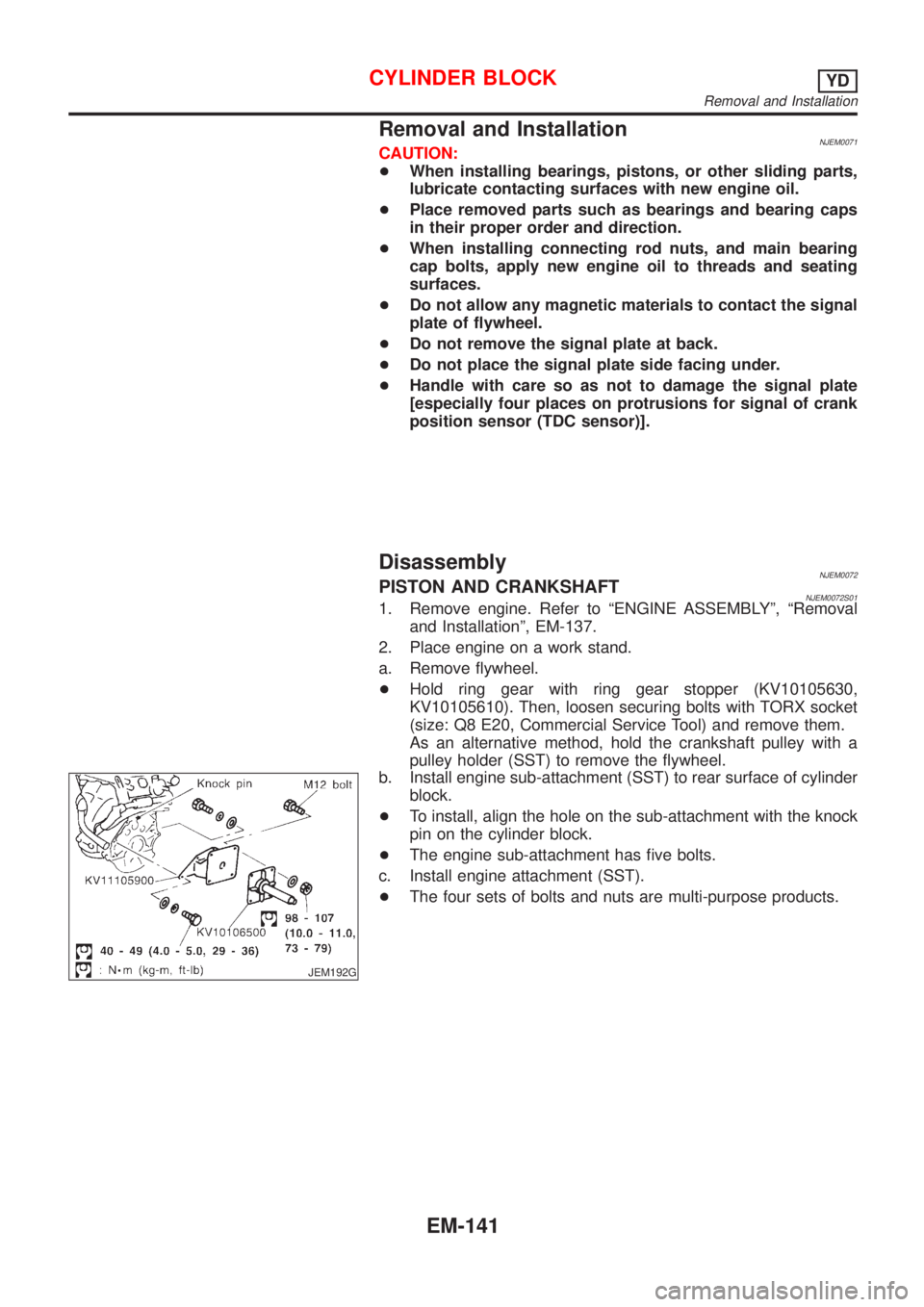
b. Install engine sub-attachment (SST) to rear surface of cylinder
block.
+To install, align the hole on the sub-attachment with the knock
pin on the cylinder block.
+The engine sub-attachment has five bolts.
c. Install engine attachment (SST).
+The four sets of bolts and nuts are multi-purpose products.
CYLINDER BLOCKYD
Removal and Installation
EM-141
Page 2276 of 2898
JEM193G
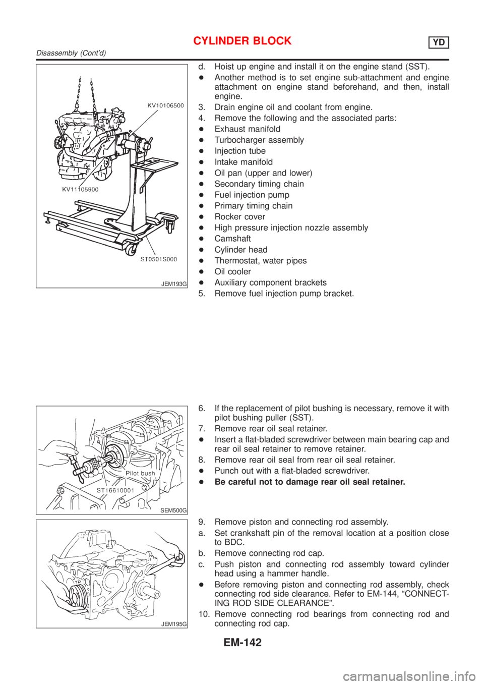
d. Hoist up engine and install it on the engine stand (SST).
+Another method is to set engine sub-attachment and engine
attachment on engine stand beforehand, and then, install
engine.
3. Drain engine oil and coolant from engine.
4. Remove the following and the associated parts:
+Exhaust manifold
+Turbocharger assembly
+Injection tube
+Intake manifold
+Oil pan (upper and lower)
+Secondary timing chain
+Fuel injection pump
+Primary timing chain
+Rocker cover
+High pressure injection nozzle assembly
+Camshaft
+Cylinder head
+Thermostat, water pipes
+Oil cooler
+Auxiliary component brackets
5. Remove fuel injection pump bracket.
SEM500G
6. If the replacement of pilot bushing is necessary, remove it with
pilot bushing puller (SST).
7. Remove rear oil seal retainer.
+Insert a flat-bladed screwdriver between main bearing cap and
rear oil seal retainer to remove retainer.
8. Remove rear oil seal from rear oil seal retainer.
+Punch out with a flat-bladed screwdriver.
+Be careful not to damage rear oil seal retainer.
JEM195G
9. Remove piston and connecting rod assembly.
a. Set crankshaft pin of the removal location at a position close
to BDC.
b. Remove connecting rod cap.
c. Push piston and connecting rod assembly toward cylinder
head using a hammer handle.
+Before removing piston and connecting rod assembly, check
connecting rod side clearance. Refer to EM-144, ªCONNECT-
ING ROD SIDE CLEARANCEº.
10. Remove connecting rod bearings from connecting rod and
connecting rod cap.
CYLINDER BLOCKYD
Disassembly (Cont'd)
EM-142
Page 2290 of 2898
JEM213G
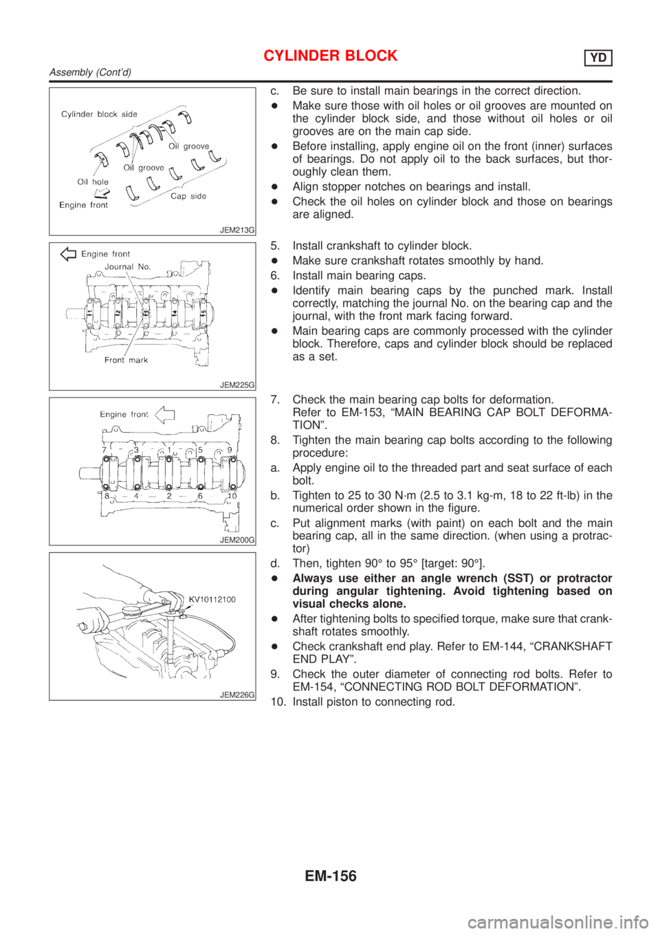
c. Be sure to install main bearings in the correct direction.
+Make sure those with oil holes or oil grooves are mounted on
the cylinder block side, and those without oil holes or oil
grooves are on the main cap side.
+Before installing, apply engine oil on the front (inner) surfaces
of bearings. Do not apply oil to the back surfaces, but thor-
oughly clean them.
+Align stopper notches on bearings and install.
+Check the oil holes on cylinder block and those on bearings
are aligned.
JEM225G
5. Install crankshaft to cylinder block.
+Make sure crankshaft rotates smoothly by hand.
6. Install main bearing caps.
+Identify main bearing caps by the punched mark. Install
correctly, matching the journal No. on the bearing cap and the
journal, with the front mark facing forward.
+Main bearing caps are commonly processed with the cylinder
block. Therefore, caps and cylinder block should be replaced
as a set.
JEM200G
JEM226G
7. Check the main bearing cap bolts for deformation.
Refer to EM-153, ªMAIN BEARING CAP BOLT DEFORMA-
TIONº.
8. Tighten the main bearing cap bolts according to the following
procedure:
a. Apply engine oil to the threaded part and seat surface of each
bolt.
b. Tighten to 25 to 30 N´m (2.5 to 3.1 kg-m, 18 to 22 ft-lb) in the
numerical order shown in the figure.
c. Put alignment marks (with paint) on each bolt and the main
bearing cap, all in the same direction. (when using a protrac-
tor)
d. Then, tighten 90É to 95É [target: 90É].
+Always use either an angle wrench (SST) or protractor
during angular tightening. Avoid tightening based on
visual checks alone.
+After tightening bolts to specified torque, make sure that crank-
shaft rotates smoothly.
+Check crankshaft end play. Refer to EM-144, ªCRANKSHAFT
END PLAYº.
9. Check the outer diameter of connecting rod bolts. Refer to
EM-154, ªCONNECTING ROD BOLT DEFORMATIONº.
10. Install piston to connecting rod.
CYLINDER BLOCKYD
Assembly (Cont'd)
EM-156
Page 2291 of 2898
JEM229G
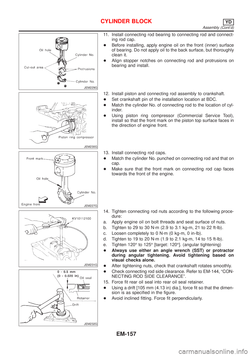
11. Install connecting rod bearing to connecting rod and connect-
ing rod cap.
+Before installing, apply engine oil on the front (inner) surface
of bearing. Do not apply oil to the back surface, but thoroughly
clean it.
+Align stopper notches on connecting rod and protrusions on
bearing and install.
JEM230G
12. Install piston and connecting rod assembly to crankshaft.
+Set crankshaft pin of the installation location at BDC.
+Match the cylinder No. of connecting rod to the location of cyl-
inder.
+Using piston ring compressor (Commercial Service Tool),
install so that the front mark on the piston top surface faces in
the direction of engine front.
JEM227G
13. Install connecting rod caps.
+Match the cylinder No. punched on connecting rod and that on
cap.
+Make sure that the front mark on connecting rod cap faces
towards the front of the engine.
JEM231G
JEM232G
14. Tighten connecting rod nuts according to the following proce-
dure:
a. Apply engine oil on bolt threads and seat surface of nuts.
b. Tighten to 29 to 30 N´m (2.9 to 3.1 kg-m, 21 to 22 ft-lb).
c. Loosen completely to 0 N´m (0 kg-m, 0 in-lb).
d. Tighten to 19 to 20 N´m (1.9 to 2.1 kg-m, 14 to 15 ft-lb).
e. Tighten 120É to 125É [target: 120É]. (angular tightening)
+Always use either an angle wrench (SST) or protractor
during angular tightening. Avoid tightening based on
visual checks alone.
+After tightening nuts, check that crankshaft rotates smoothly.
+Check connecting rod side clearance. Refer to EM-144, ªCON-
NECTING ROD SIDE CLEARANCEº.
15. Force fit rear oil seal into rear oil seal retainer.
+Using a drift [105 mm (4.13 in) dia.], force fit so that the dimen-
sion is as specified in the figure.
+Avoid inclined fitting. Force fit perpendicularly.
CYLINDER BLOCKYD
Assembly (Cont'd)
EM-157