Page 2508 of 2898
REGULATOR VALVE INSPECTION..........................35
OIL PUMP INSPECTION..........................................35
ENGINE OIL CAPACITY...........................................35
ENGINE COOLING SYSTEM........................................36
Precautions ................................................................36
LIQUID GASKET APPLICATION PROCEDURE..........36
Preparation ................................................................36
SPECIAL SERVICE TOOLS......................................36
Cooling Circuit ...........................................................37
System Check............................................................38
CHECKING COOLING SYSTEM HOSES...................38
CHECKING RADIATOR............................................38
CHECKING RADIATOR CAP....................................38
CHECKING COOLING SYSTEM FOR LEAKS............39
Water Pump ...............................................................39
REMOVAL AND INSTALLATION...............................39
REMOVAL...............................................................40
INSPECTION...........................................................40
INSTALLATION........................................................40
Thermostat .................................................................41
REMOVAL AND INSTALLATION...............................41
INSPECTION...........................................................42
Radiator .....................................................................42
COMPONENTS.......................................................42
REMOVAL AND INSTALLATION...............................43
Cooling Fan ...............................................................43
COMPONENTS.......................................................43
CONTROL SYSTEM................................................43
Changing Engine Coolant..........................................44
- DRAINING ENGINE COOLANT -............................44
- REFILLING ENGINE COOLANT -...........................45
- FLUSHING COOLING SYSTEM -............................46
Radiator (Aluminum type) ..........................................47
Overheating Cause Analysis .....................................47
Service Data and Specifications (SDS).....................48
THERMOSTAT........................................................48
RADIATOR..............................................................48
ENGINE COOLANT CAPACITY................................48
CONTENTS(Cont'd)
LC-2
Page 2509 of 2898
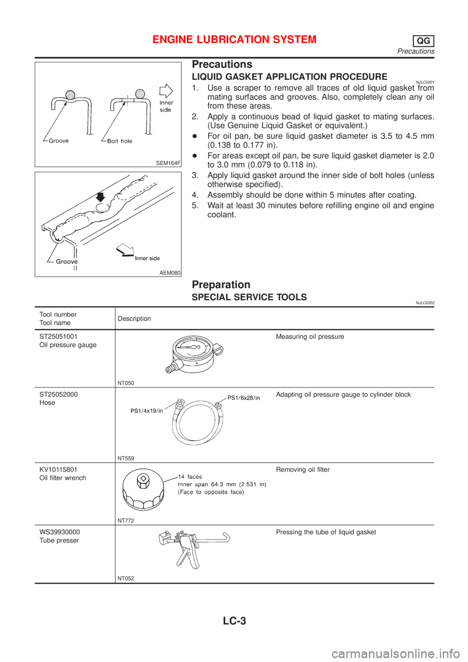
SEM164F
AEM080
Precautions
LIQUID GASKET APPLICATION PROCEDURENJLC00011. Use a scraper to remove all traces of old liquid gasket from
mating surfaces and grooves. Also, completely clean any oil
from these areas.
2. Apply a continuous bead of liquid gasket to mating surfaces.
(Use Genuine Liquid Gasket or equivalent.)
+For oil pan, be sure liquid gasket diameter is 3.5 to 4.5 mm
(0.138 to 0.177 in).
+For areas except oil pan, be sure liquid gasket diameter is 2.0
to 3.0 mm (0.079 to 0.118 in).
3. Apply liquid gasket around the inner side of bolt holes (unless
otherwise specified).
4. Assembly should be done within 5 minutes after coating.
5. Wait at least 30 minutes before refilling engine oil and engine
coolant.
Preparation
SPECIAL SERVICE TOOLSNJLC0002
Tool number
Tool nameDescription
ST25051001
Oil pressure gauge
NT050
Measuring oil pressure
ST25052000
Hose
NT559
Adapting oil pressure gauge to cylinder block
KV10115801
Oil filter wrench
NT772
Removing oil filter
WS39930000
Tube presser
NT052
Pressing the tube of liquid gasket
ENGINE LUBRICATION SYSTEMQG
Precautions
LC-3
Page 2511 of 2898
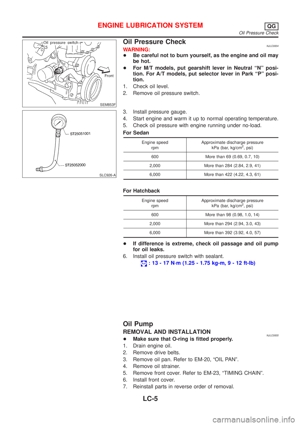
SEM853F
Oil Pressure CheckNJLC0004WARNING:
+Be careful not to burn yourself, as the engine and oil may
be hot.
+For M/T models, put gearshift lever in Neutral ªNº posi-
tion. For A/T models, put selector lever in Park ªPº posi-
tion.
1. Check oil level.
2. Remove oil pressure switch.
SLC926-A
3. Install pressure gauge.
4. Start engine and warm it up to normal operating temperature.
5. Check oil pressure with engine running under no-load.
For Sedan
Engine speed
rpmApproximate discharge pressure
kPa (bar, kg/cm2, psi)
600 More than 69 (0.69, 0.7, 10)
2,000 More than 284 (2.84, 2.9, 41)
6,000 More than 422 (4.22, 4.3, 61)
For Hatchback
Engine speed
rpmApproximate discharge pressure
kPa (bar, kg/cm2, psi)
600 More than 98 (0.98, 1.0, 14)
2,000 More than 294 (2.94, 3.0, 43)
6,000 More than 392 (3.92, 4.0, 57)
+If difference is extreme, check oil passage and oil pump
for oil leaks.
6. Install oil pressure switch with sealant.
: 13 - 17 N´m (1.25 - 1.75 kg-m,9-12ft-lb)
Oil Pump
REMOVAL AND INSTALLATIONNJLC0005+Make sure that O-ring is fitted properly.
1. Drain engine oil.
2. Remove drive belts.
3. Remove oil pan. Refer to EM-20, ªOIL PANº.
4. Remove oil strainer.
5. Remove front cover. Refer to EM-23, ªTIMING CHAINº.
6. Install front cover.
7. Reinstall parts in reverse order of removal.
ENGINE LUBRICATION SYSTEMQG
Oil Pressure Check
LC-5
Page 2512 of 2898
DISASSEMBLY AND ASSEMBLYNJLC0006
SLC412BA
1. Oil pump cover
2. Inner rotor
3. Outer rotor4. Front cover
5. Oil strainer
6. Regulator valve7. Spring
8. Washer
9. Plug
+When installing oil pump, apply engine oil to rotors.
JLC307B
+Install the inner rotor and outer rotor with the punched
marks on the oil pump cover side.
ENGINE LUBRICATION SYSTEMQG
Oil Pump (Cont'd)
LC-6
Page 2513 of 2898
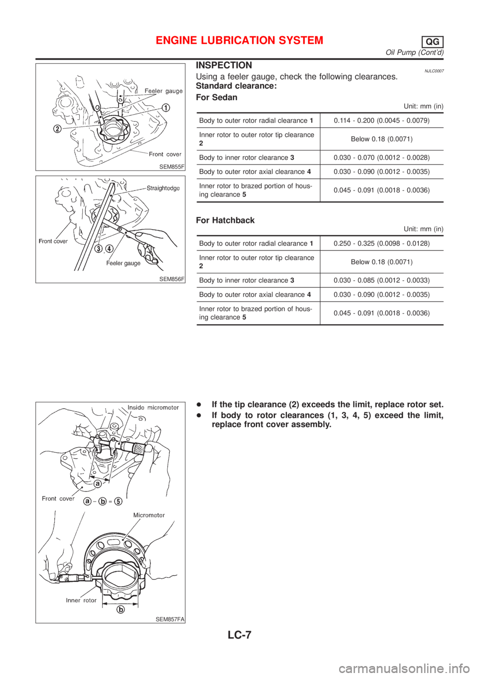
SEM855F
SEM856F
INSPECTIONNJLC0007Using a feeler gauge, check the following clearances.
Standard clearance:
For Sedan
Unit: mm (in)
Body to outer rotor radial clearance10.114 - 0.200 (0.0045 - 0.0079)
Inner rotor to outer rotor tip clearance
2Below 0.18 (0.0071)
Body to inner rotor clearance30.030 - 0.070 (0.0012 - 0.0028)
Body to outer rotor axial clearance40.030 - 0.090 (0.0012 - 0.0035)
Inner rotor to brazed portion of hous-
ing clearance50.045 - 0.091 (0.0018 - 0.0036)
For Hatchback
Unit: mm (in)
Body to outer rotor radial clearance10.250 - 0.325 (0.0098 - 0.0128)
Inner rotor to outer rotor tip clearance
2Below 0.18 (0.0071)
Body to inner rotor clearance30.030 - 0.085 (0.0012 - 0.0033)
Body to outer rotor axial clearance40.030 - 0.090 (0.0012 - 0.0035)
Inner rotor to brazed portion of hous-
ing clearance50.045 - 0.091 (0.0018 - 0.0036)
SEM857FA
+If the tip clearance (2) exceeds the limit, replace rotor set.
+If body to rotor clearances (1, 3, 4, 5) exceed the limit,
replace front cover assembly.
ENGINE LUBRICATION SYSTEMQG
Oil Pump (Cont'd)
LC-7
Page 2514 of 2898
SLC986AA
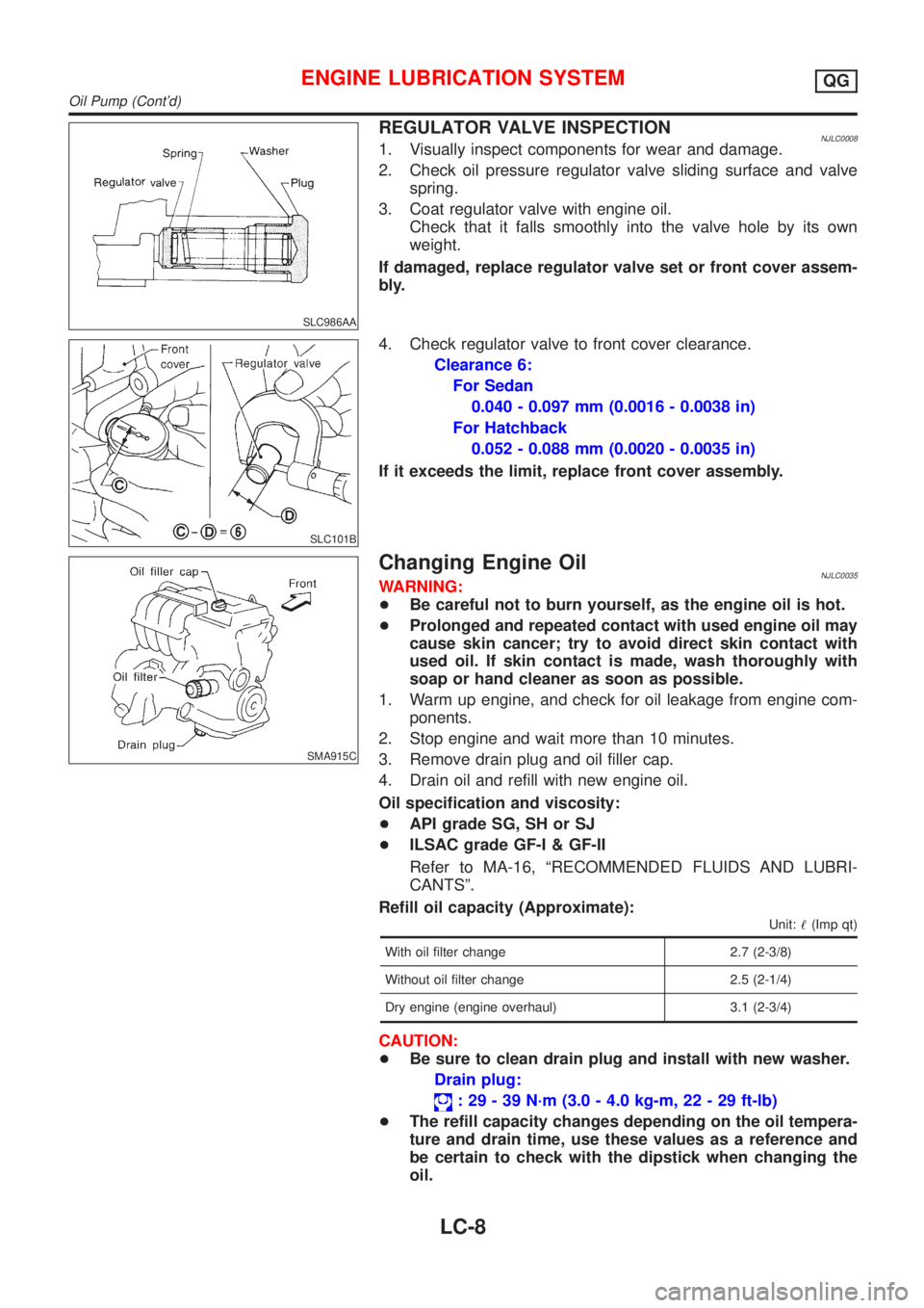
REGULATOR VALVE INSPECTIONNJLC00081. Visually inspect components for wear and damage.
2. Check oil pressure regulator valve sliding surface and valve
spring.
3. Coat regulator valve with engine oil.
Check that it falls smoothly into the valve hole by its own
weight.
If damaged, replace regulator valve set or front cover assem-
bly.
SLC101B
4. Check regulator valve to front cover clearance.
Clearance 6:
For Sedan
0.040 - 0.097 mm (0.0016 - 0.0038 in)
For Hatchback
0.052 - 0.088 mm (0.0020 - 0.0035 in)
If it exceeds the limit, replace front cover assembly.
SMA915C
Changing Engine OilNJLC0035WARNING:
+Be careful not to burn yourself, as the engine oil is hot.
+Prolonged and repeated contact with used engine oil may
cause skin cancer; try to avoid direct skin contact with
used oil. If skin contact is made, wash thoroughly with
soap or hand cleaner as soon as possible.
1. Warm up engine, and check for oil leakage from engine com-
ponents.
2. Stop engine and wait more than 10 minutes.
3. Remove drain plug and oil filler cap.
4. Drain oil and refill with new engine oil.
Oil specification and viscosity:
+API grade SG, SH or SJ
+ILSAC grade GF-I & GF-II
Refer to MA-16, ªRECOMMENDED FLUIDS AND LUBRI-
CANTSº.
Refill oil capacity (Approximate):
Unit:!(Imp qt)
With oil filter change 2.7 (2-3/8)
Without oil filter change 2.5 (2-1/4)
Dry engine (engine overhaul) 3.1 (2-3/4)
CAUTION:
+Be sure to clean drain plug and install with new washer.
Drain plug:
: 29 - 39 N´m (3.0 - 4.0 kg-m, 22 - 29 ft-lb)
+The refill capacity changes depending on the oil tempera-
ture and drain time, use these values as a reference and
be certain to check with the dipstick when changing the
oil.
ENGINE LUBRICATION SYSTEMQG
Oil Pump (Cont'd)
LC-8
Page 2515 of 2898
SMA390C
5. Check oil level.
6. Start engine and check area around drain plug and oil filter for
oil leakage.
7. Run engine for a few minutes, then turn it off. After several
minutes, check oil level.
ALC094
Changing Oil FilterNJLC0010The oil filter is a small, full-flow cartridge type and is provided with
a relief valve.
+Use Tool KV10115801 for removing oil filter.
SLC275B
1. Remove oil filter with Tool.
WARNING:
Be careful not to burn yourself, as the engine and the engine
oil are hot.
SMA010
2. Clean oil filter mounting surface on cylinder block. Coat rubber
seal of new oil filter with engine oil.
SMA229B
3. Screw in the oil filter until a slight resistance is felt, then tighten
an additional 2/3 turn.
4. Add engine oil.
Refer to Changing Engine Oil.
+Clean excess oil from engine.
ENGINE LUBRICATION SYSTEMQG
Changing Engine Oil (Cont'd)
LC-9
Page 2516 of 2898
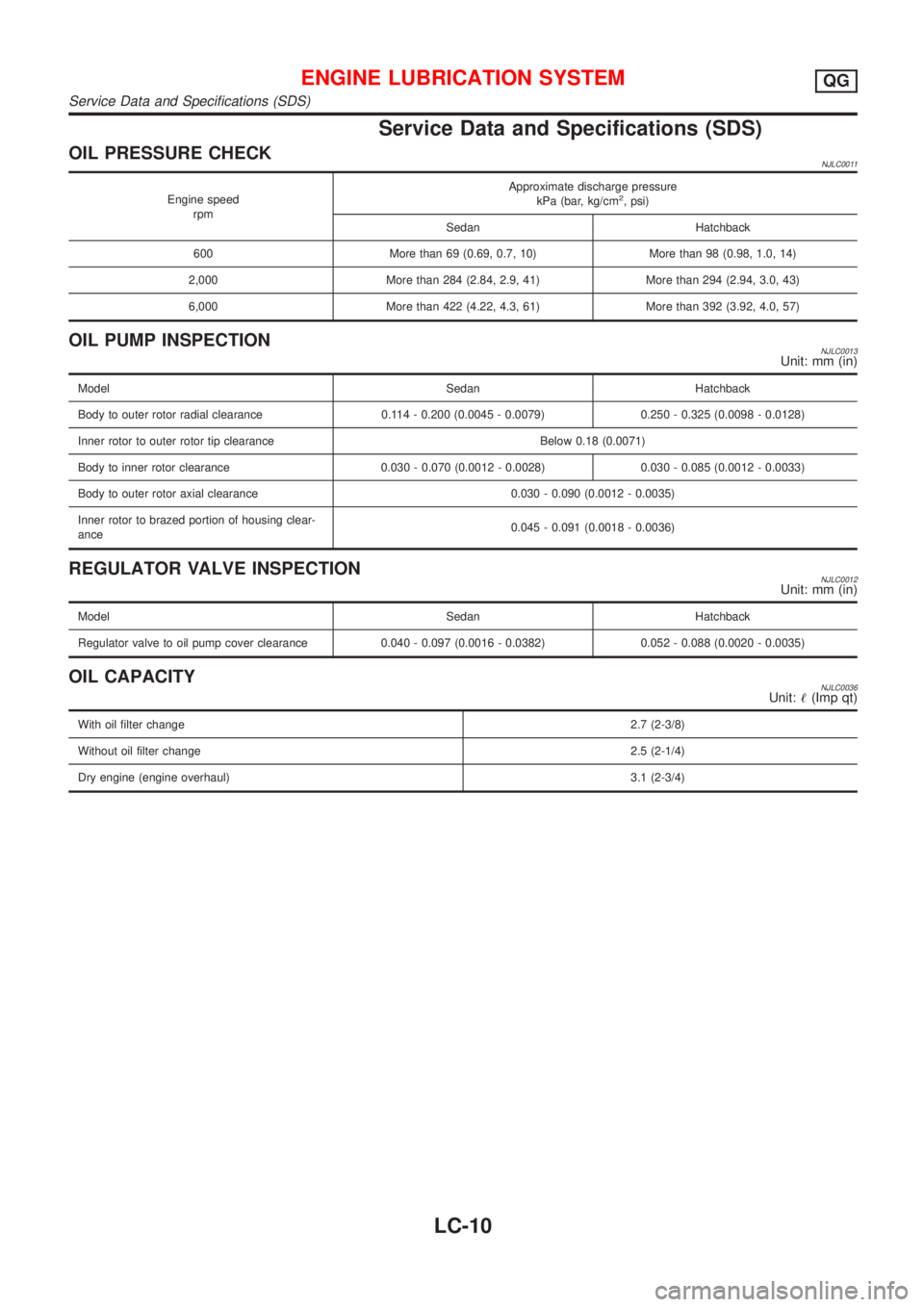
Service Data and Specifications (SDS)
OIL PRESSURE CHECKNJLC0011
Engine speed
rpmApproximate discharge pressure
kPa (bar, kg/cm2, psi)
Sedan Hatchback
600 More than 69 (0.69, 0.7, 10) More than 98 (0.98, 1.0, 14)
2,000 More than 284 (2.84, 2.9, 41) More than 294 (2.94, 3.0, 43)
6,000 More than 422 (4.22, 4.3, 61) More than 392 (3.92, 4.0, 57)
OIL PUMP INSPECTIONNJLC0013Unit: mm (in)
Model Sedan Hatchback
Body to outer rotor radial clearance 0.114 - 0.200 (0.0045 - 0.0079) 0.250 - 0.325 (0.0098 - 0.0128)
Inner rotor to outer rotor tip clearance Below 0.18 (0.0071)
Body to inner rotor clearance 0.030 - 0.070 (0.0012 - 0.0028) 0.030 - 0.085 (0.0012 - 0.0033)
Body to outer rotor axial clearance 0.030 - 0.090 (0.0012 - 0.0035)
Inner rotor to brazed portion of housing clear-
ance0.045 - 0.091 (0.0018 - 0.0036)
REGULATOR VALVE INSPECTIONNJLC0012Unit: mm (in)
Model Sedan Hatchback
Regulator valve to oil pump cover clearance 0.040 - 0.097 (0.0016 - 0.0382) 0.052 - 0.088 (0.0020 - 0.0035)
OIL CAPACITYNJLC0036Unit:!(Imp qt)
With oil filter change2.7 (2-3/8)
Without oil filter change2.5 (2-1/4)
Dry engine (engine overhaul)3.1 (2-3/4)
ENGINE LUBRICATION SYSTEMQG
Service Data and Specifications (SDS)
LC-10