2001 NISSAN ALMERA engine oil
[x] Cancel search: engine oilPage 2234 of 2898
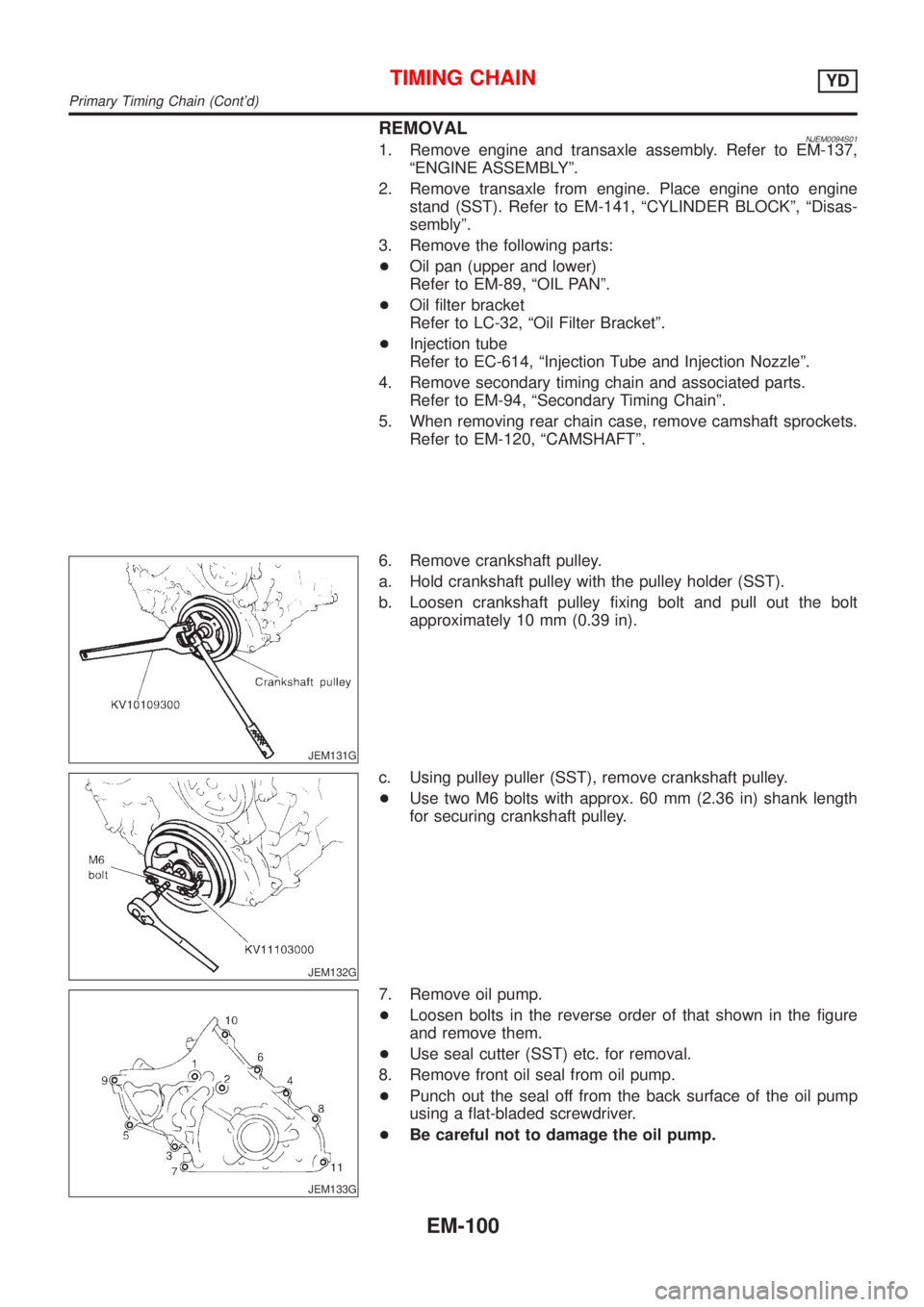
REMOVALNJEM0094S011. Remove engine and transaxle assembly. Refer to EM-137,
ªENGINE ASSEMBLYº.
2. Remove transaxle from engine. Place engine onto engine
stand (SST). Refer to EM-141, ªCYLINDER BLOCKº, ªDisas-
semblyº.
3. Remove the following parts:
+Oil pan (upper and lower)
Refer to EM-89, ªOIL PANº.
+Oil filter bracket
Refer to LC-32, ªOil Filter Bracketº.
+Injection tube
Refer to EC-614, ªInjection Tube and Injection Nozzleº.
4. Remove secondary timing chain and associated parts.
Refer to EM-94, ªSecondary Timing Chainº.
5. When removing rear chain case, remove camshaft sprockets.
Refer to EM-120, ªCAMSHAFTº.
JEM131G
6. Remove crankshaft pulley.
a. Hold crankshaft pulley with the pulley holder (SST).
b. Loosen crankshaft pulley fixing bolt and pull out the bolt
approximately 10 mm (0.39 in).
JEM132G
c. Using pulley puller (SST), remove crankshaft pulley.
+Use two M6 bolts with approx. 60 mm (2.36 in) shank length
for securing crankshaft pulley.
JEM133G
7. Remove oil pump.
+Loosen bolts in the reverse order of that shown in the figure
and remove them.
+Use seal cutter (SST) etc. for removal.
8. Remove front oil seal from oil pump.
+Punch out the seal off from the back surface of the oil pump
using a flat-bladed screwdriver.
+Be careful not to damage the oil pump.
TIMING CHAINYD
Primary Timing Chain (Cont'd)
EM-100
Page 2237 of 2898
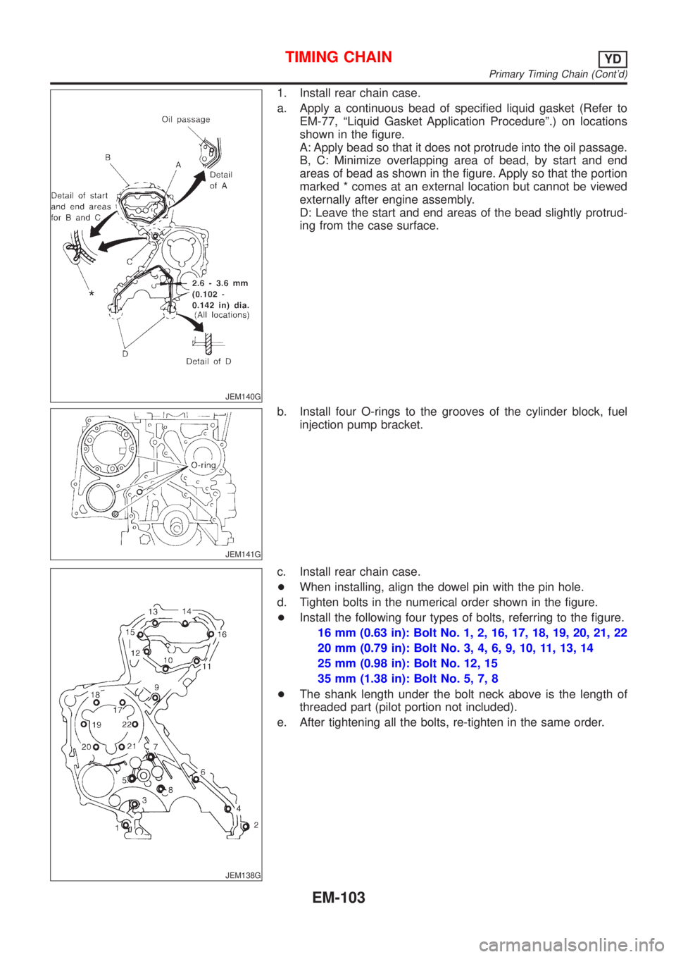
JEM140G
1. Install rear chain case.
a. Apply a continuous bead of specified liquid gasket (Refer to
EM-77, ªLiquid Gasket Application Procedureº.) on locations
shown in the figure.
A: Apply bead so that it does not protrude into the oil passage.
B, C: Minimize overlapping area of bead, by start and end
areas of bead as shown in the figure. Apply so that the portion
marked * comes at an external location but cannot be viewed
externally after engine assembly.
D: Leave the start and end areas of the bead slightly protrud-
ing from the case surface.
JEM141G
b. Install four O-rings to the grooves of the cylinder block, fuel
injection pump bracket.
JEM138G
c. Install rear chain case.
+When installing, align the dowel pin with the pin hole.
d. Tighten bolts in the numerical order shown in the figure.
+Install the following four types of bolts, referring to the figure.
16 mm (0.63 in): Bolt No. 1, 2, 16, 17, 18, 19, 20, 21, 22
20 mm (0.79 in): Bolt No. 3, 4, 6, 9, 10, 11, 13, 14
25 mm (0.98 in): Bolt No. 12, 15
35 mm (1.38 in): Bolt No. 5, 7, 8
+The shank length under the bolt neck above is the length of
threaded part (pilot portion not included).
e. After tightening all the bolts, re-tighten in the same order.
TIMING CHAINYD
Primary Timing Chain (Cont'd)
EM-103
Page 2238 of 2898
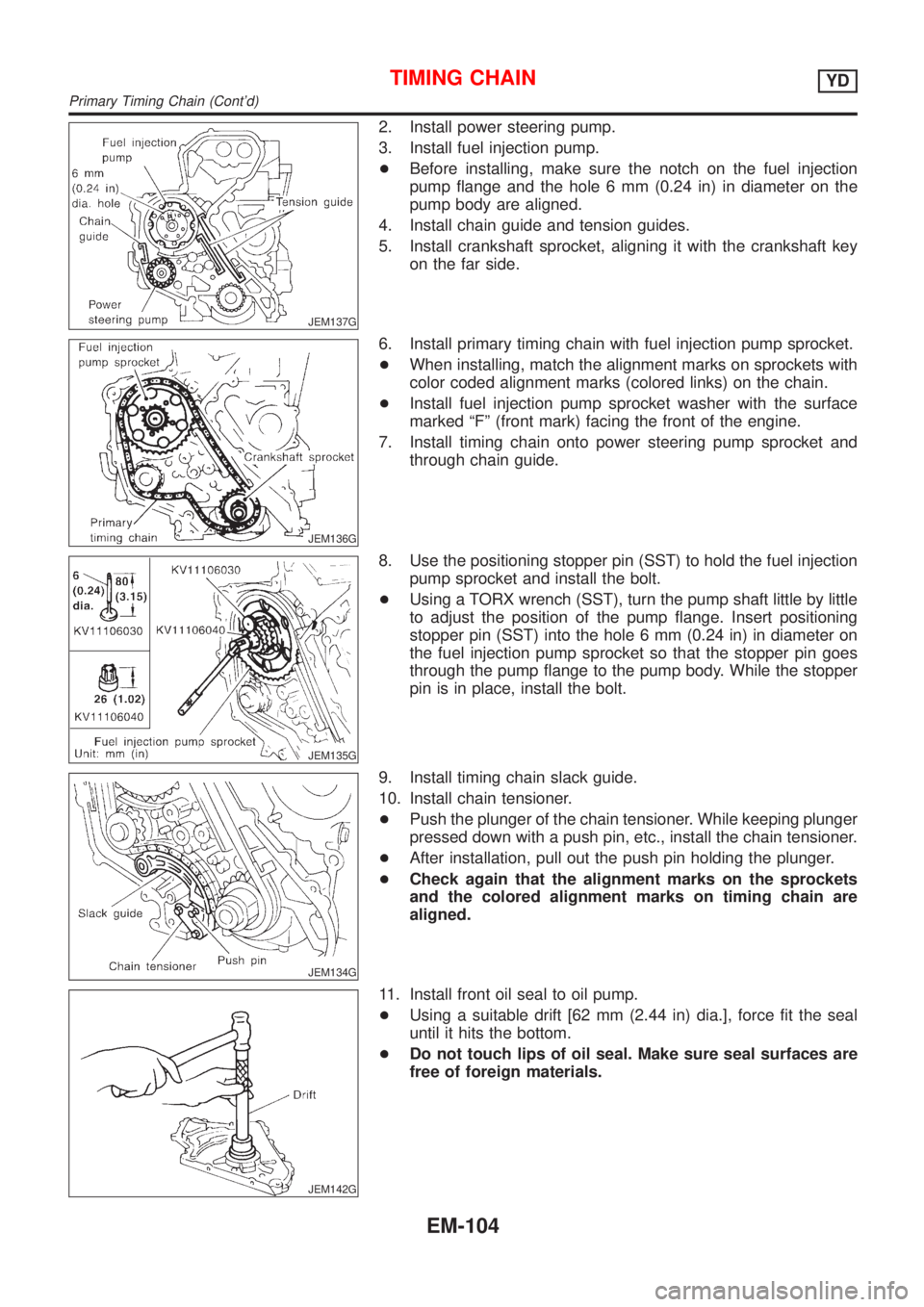
JEM137G
2. Install power steering pump.
3. Install fuel injection pump.
+Before installing, make sure the notch on the fuel injection
pump flange and the hole 6 mm (0.24 in) in diameter on the
pump body are aligned.
4. Install chain guide and tension guides.
5. Install crankshaft sprocket, aligning it with the crankshaft key
on the far side.
JEM136G
6. Install primary timing chain with fuel injection pump sprocket.
+When installing, match the alignment marks on sprockets with
color coded alignment marks (colored links) on the chain.
+Install fuel injection pump sprocket washer with the surface
marked ªFº (front mark) facing the front of the engine.
7. Install timing chain onto power steering pump sprocket and
through chain guide.
JEM135G
8. Use the positioning stopper pin (SST) to hold the fuel injection
pump sprocket and install the bolt.
+Using a TORX wrench (SST), turn the pump shaft little by little
to adjust the position of the pump flange. Insert positioning
stopper pin (SST) into the hole 6 mm (0.24 in) in diameter on
the fuel injection pump sprocket so that the stopper pin goes
through the pump flange to the pump body. While the stopper
pin is in place, install the bolt.
JEM134G
9. Install timing chain slack guide.
10. Install chain tensioner.
+Push the plunger of the chain tensioner. While keeping plunger
pressed down with a push pin, etc., install the chain tensioner.
+After installation, pull out the push pin holding the plunger.
+Check again that the alignment marks on the sprockets
and the colored alignment marks on timing chain are
aligned.
JEM142G
11. Install front oil seal to oil pump.
+Using a suitable drift [62 mm (2.44 in) dia.], force fit the seal
until it hits the bottom.
+Do not touch lips of oil seal. Make sure seal surfaces are
free of foreign materials.
TIMING CHAINYD
Primary Timing Chain (Cont'd)
EM-104
Page 2239 of 2898
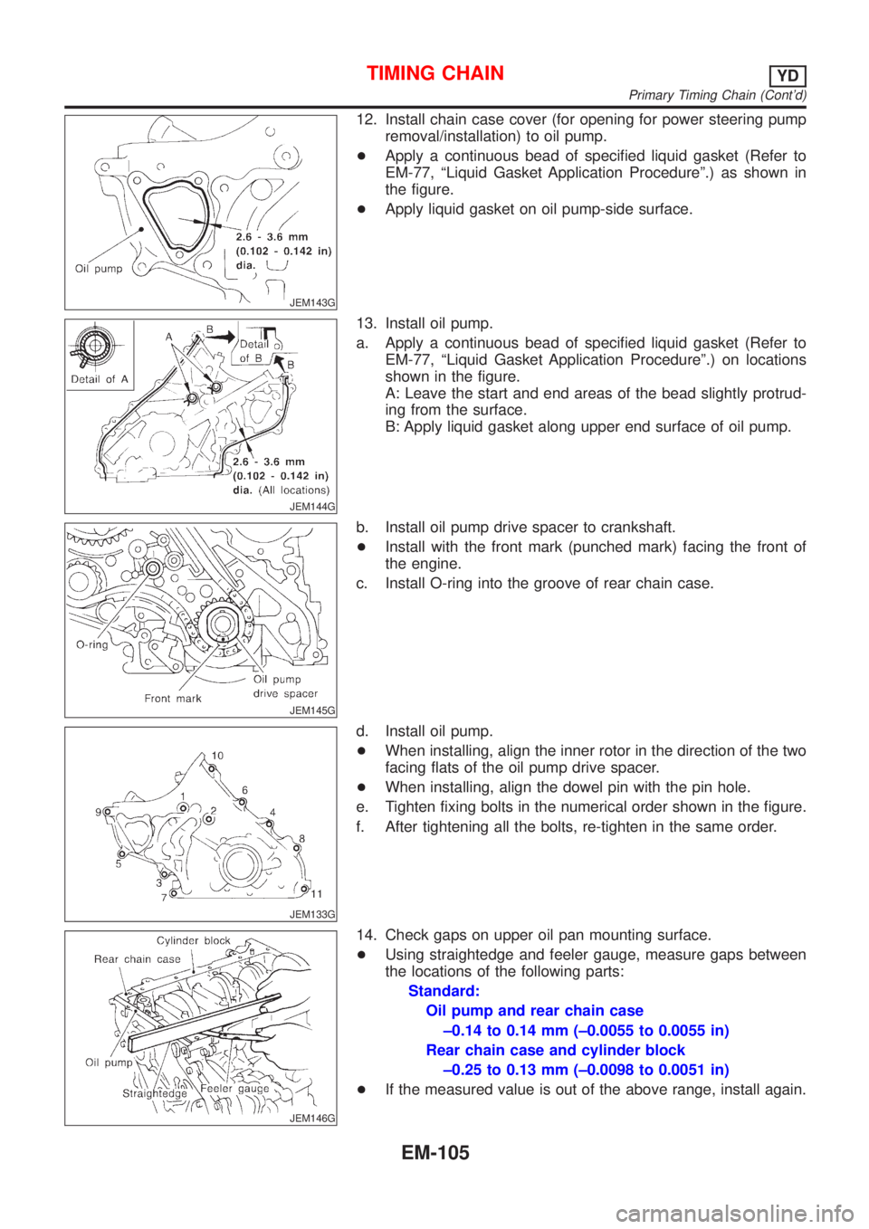
JEM143G
12. Install chain case cover (for opening for power steering pump
removal/installation) to oil pump.
+Apply a continuous bead of specified liquid gasket (Refer to
EM-77, ªLiquid Gasket Application Procedureº.) as shown in
the figure.
+Apply liquid gasket on oil pump-side surface.
JEM144G
13. Install oil pump.
a. Apply a continuous bead of specified liquid gasket (Refer to
EM-77, ªLiquid Gasket Application Procedureº.) on locations
shown in the figure.
A: Leave the start and end areas of the bead slightly protrud-
ing from the surface.
B: Apply liquid gasket along upper end surface of oil pump.
JEM145G
b. Install oil pump drive spacer to crankshaft.
+Install with the front mark (punched mark) facing the front of
the engine.
c. Install O-ring into the groove of rear chain case.
JEM133G
d. Install oil pump.
+When installing, align the inner rotor in the direction of the two
facing flats of the oil pump drive spacer.
+When installing, align the dowel pin with the pin hole.
e. Tighten fixing bolts in the numerical order shown in the figure.
f. After tightening all the bolts, re-tighten in the same order.
JEM146G
14. Check gaps on upper oil pan mounting surface.
+Using straightedge and feeler gauge, measure gaps between
the locations of the following parts:
Standard:
Oil pump and rear chain case
±0.14 to 0.14 mm (±0.0055 to 0.0055 in)
Rear chain case and cylinder block
±0.25 to 0.13 mm (±0.0098 to 0.0051 in)
+If the measured value is out of the above range, install again.
TIMING CHAINYD
Primary Timing Chain (Cont'd)
EM-105
Page 2250 of 2898
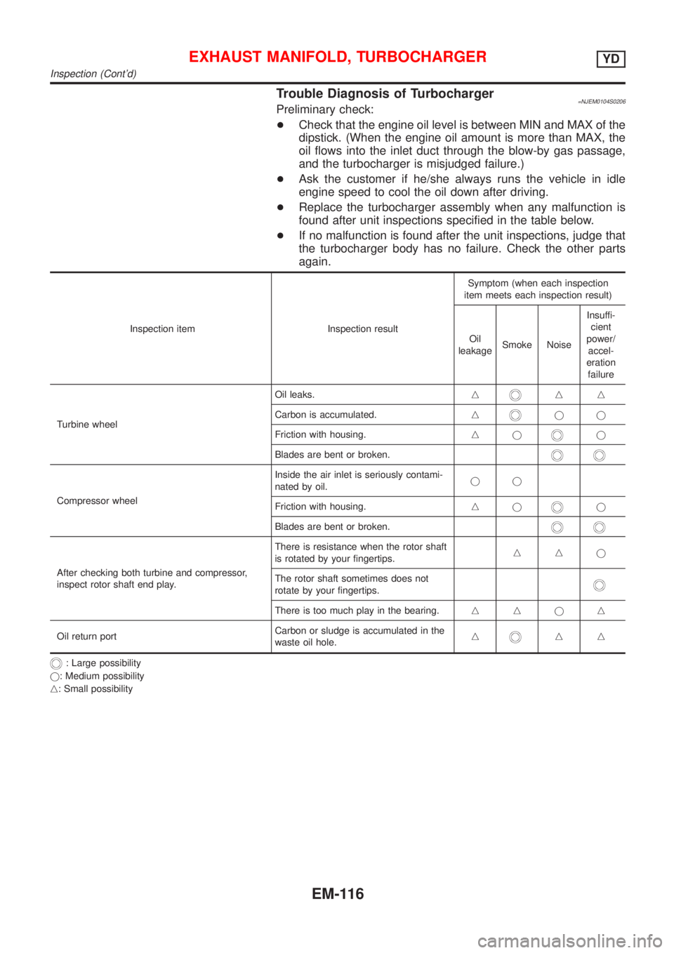
Trouble Diagnosis of Turbocharger=NJEM0104S0206Preliminary check:
+Check that the engine oil level is between MIN and MAX of the
dipstick. (When the engine oil amount is more than MAX, the
oil flows into the inlet duct through the blow-by gas passage,
and the turbocharger is misjudged failure.)
+Ask the customer if he/she always runs the vehicle in idle
engine speed to cool the oil down after driving.
+Replace the turbocharger assembly when any malfunction is
found after unit inspections specified in the table below.
+If no malfunction is found after the unit inspections, judge that
the turbocharger body has no failure. Check the other parts
again.
Inspection item Inspection resultSymptom (when each inspection
item meets each inspection result)
Oil
leakageSmoke NoiseInsuffi-
cient
power/
accel-
eration
failure
Turbine wheelOil leaks.n
nn
Carbon is accumulated.n
jj
Friction with housing.nj
j
Blades are bent or broken.
Compressor wheelInside the air inlet is seriously contami-
nated by oil.jj
Friction with housing.njj
Blades are bent or broken.
After checking both turbine and compressor,
inspect rotor shaft end play.There is resistance when the rotor shaft
is rotated by your fingertips.nnj
The rotor shaft sometimes does not
rotate by your fingertips.
There is too much play in the bearing.nnjn
Oil return portCarbon or sludge is accumulated in the
waste oil hole.n
nn
: Large possibility
j: Medium possibility
n: Small possibility
EXHAUST MANIFOLD, TURBOCHARGERYD
Inspection (Cont'd)
EM-116
Page 2254 of 2898
CAUTION:
+When installing camshafts, chain tensioners, oil seals, or
other sliding parts, lubricate contacting surfaces with new
engine oil.
+Apply new engine oil to threads and seat surfaces when
installing cylinder head, camshaft sprocket, crankshaft
pulley, and camshaft bracket.
+Attach tags to valve lifters so as not to mix them up.
RemovalNJEM0063PREPARATIVE WORKNJEM0063S011. Drain engine coolant. Refer to LC-44, ªChanging Engine Cool-
antº.
2. Remove exhaust manifold. Refer to EM-112, ªRemovalº.
3. Remove intake manifold. Refer to EM-108, ªRemovalº.
+Apply paint to camshaft sprockets for alignment during
installation.
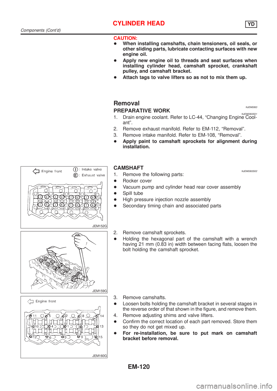
JEM152G
CAMSHAFTNJEM0063S021. Remove the following parts:
+Rocker cover
+Vacuum pump and cylinder head rear cover assembly
+Spill tube
+High pressure injection nozzle assembly
+Secondary timing chain and associated parts
JEM159G
2. Remove camshaft sprockets.
+Holding the hexagonal part of the camshaft with a wrench
having 21 mm (0.83 in) width between facing flats, loosen the
bolt holding the camshaft sprocket.
JEM160G
3. Remove camshafts.
+Loosen bolts holding the camshaft bracket in several stages in
the reverse order of that shown in the figure, and remove them.
4. Remove adjusting shims and valve lifters.
+Confirm the correct location of each part removed. Store them
so they do not get mixed up.
+For re-installation, be sure to put mark on camshaft
bracket before removal.
CYLINDER HEADYD
Components (Cont'd)
EM-120
Page 2265 of 2898
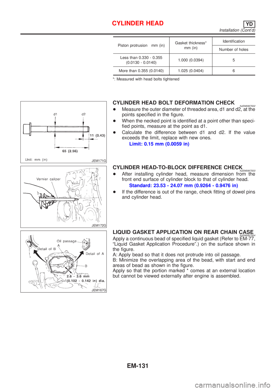
Piston protrusion mm (in)Gasket thickness*
mm (in)Identification
Number of holes
Less than 0.330 - 0.355
(0.0130 - 0.0140)1.000 (0.0394) 5
More than 0.355 (0.0140) 1.025 (0.0404) 6
*: Measured with head bolts tightened
JEM171G
CYLINDER HEAD BOLT DEFORMATION CHECKNJEM0067S02+Measure the outer diameter of threaded area, d1 and d2, at the
points specified in the figure.
+When the necked point is identified at a point other than speci-
fied points, measure at the point as d1.
+Calculate the difference between d1 and d2. If the value
exceeds the limit, replace with new ones.
Limit: 0.15 mm (0.0059 in)
JEM172G
CYLINDER HEAD-TO-BLOCK DIFFERENCE CHECKNJEM0067S03+After installing cylinder head, measure dimension from the
front end surface of cylinder block to that of cylinder head.
Standard: 23.53 - 24.07 mm (0.9264 - 0.9476 in)
+If the difference is out of the range, check fitting of dowel pins
and cylinder head.
JEM167G
LIQUID GASKET APPLICATION ON REAR CHAIN CASENJEM0067S04Apply a continuous bead of specified liquid gasket (Refer to EM-77,
ªLiquid Gasket Application Procedureº.) on the surface shown in
the figure.
A: Apply bead so that it does not protrude into oil passage.
B: Minimize the overlapping area of the bead, with start and end
areas of bead as shown in the figure.
Apply so that the portion marked * comes at an external location
but cannot be viewed externally after engine is assembled.
CYLINDER HEADYD
Installation (Cont'd)
EM-131
Page 2266 of 2898
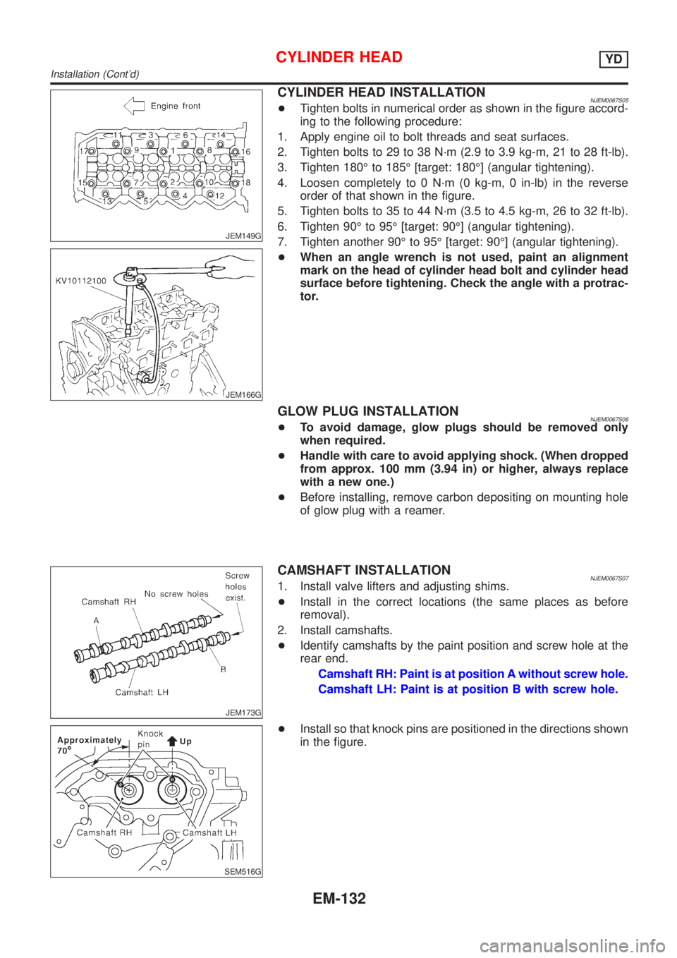
JEM149G
JEM166G
CYLINDER HEAD INSTALLATIONNJEM0067S05+Tighten bolts in numerical order as shown in the figure accord-
ing to the following procedure:
1. Apply engine oil to bolt threads and seat surfaces.
2. Tighten bolts to 29 to 38 N´m (2.9 to 3.9 kg-m, 21 to 28 ft-lb).
3. Tighten 180É to 185É [target: 180É] (angular tightening).
4. Loosen completely to 0 N´m (0 kg-m, 0 in-lb) in the reverse
order of that shown in the figure.
5. Tighten bolts to 35 to 44 N´m (3.5 to 4.5 kg-m, 26 to 32 ft-lb).
6. Tighten 90É to 95É [target: 90É] (angular tightening).
7. Tighten another 90É to 95É [target: 90É] (angular tightening).
+When an angle wrench is not used, paint an alignment
mark on the head of cylinder head bolt and cylinder head
surface before tightening. Check the angle with a protrac-
tor.
GLOW PLUG INSTALLATIONNJEM0067S06+To avoid damage, glow plugs should be removed only
when required.
+Handle with care to avoid applying shock. (When dropped
from approx. 100 mm (3.94 in) or higher, always replace
with a new one.)
+Before installing, remove carbon depositing on mounting hole
of glow plug with a reamer.
JEM173G
CAMSHAFT INSTALLATIONNJEM0067S071. Install valve lifters and adjusting shims.
+Install in the correct locations (the same places as before
removal).
2. Install camshafts.
+Identify camshafts by the paint position and screw hole at the
rear end.
Camshaft RH: Paint is at position A without screw hole.
Camshaft LH: Paint is at position B with screw hole.
SEM516G
+Install so that knock pins are positioned in the directions shown
in the figure.
CYLINDER HEADYD
Installation (Cont'd)
EM-132