Page 2537 of 2898

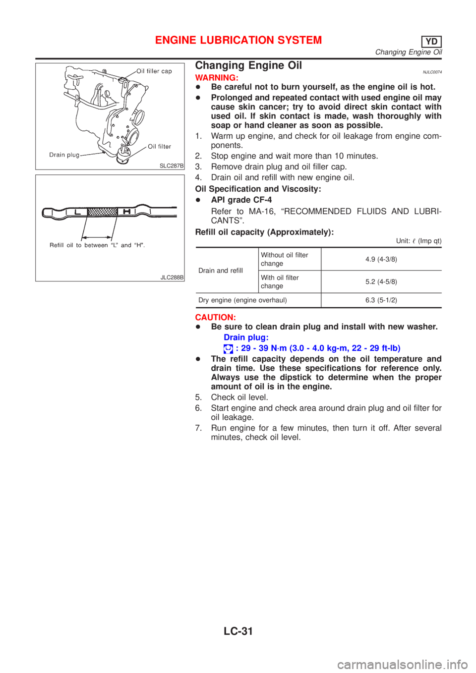
SLC287B
JLC288B
Changing Engine OilNJLC0074WARNING:
+Be careful not to burn yourself, as the engine oil is hot.
+Prolonged and repeated contact with used engine oil may
cause skin cancer; try to avoid direct skin contact with
used oil. If skin contact is made, wash thoroughly with
soap or hand cleaner as soon as possible.
1. Warm up engine, and check for oil leakage from engine com-
ponents.
2. Stop engine and wait more than 10 minutes.
3. Remove drain plug and oil filler cap.
4. Drain oil and refill with new engine oil.
Oil Specification and Viscosity:
+API grade CF-4
Refer to MA-16, ªRECOMMENDED FLUIDS AND LUBRI-
CANTSº.
Refill oil capacity (Approximately):
Unit:!(Imp qt)
Drain and refillWithout oil filter
change4.9 (4-3/8)
With oil filter
change5.2 (4-5/8)
Dry engine (engine overhaul) 6.3 (5-1/2)
CAUTION:
+Be sure to clean drain plug and install with new washer.
Drain plug:
: 29 - 39 N´m (3.0 - 4.0 kg-m, 22 - 29 ft-lb)
+The refill capacity depends on the oil temperature and
drain time. Use these specifications for reference only.
Always use the dipstick to determine when the proper
amount of oil is in the engine.
5. Check oil level.
6. Start engine and check area around drain plug and oil filter for
oil leakage.
7. Run engine for a few minutes, then turn it off. After several
minutes, check oil level.
ENGINE LUBRICATION SYSTEMYD
Changing Engine Oil
LC-31
Page 2538 of 2898
Oil Filter BracketNJLC0075
JLC301B
REMOVAL AND INSTALLATIONNJLC0075S011. Remove the undercover.
2. Steer the front wheel to the right.
3. Remove the right splash cover.
4. Remove the oil filter bracket bolt.
5. Reinstall all removed parts in the reverse order of removal.
+Insert the top mounting bolt to the oil filter bracket beforehand,
and set the oil filter bracket to the installation location.
JLC289B
Changing Oil FilterNJLC0076
ENGINE LUBRICATION SYSTEMYD
Oil Filter Bracket
LC-32
Page 2539 of 2898
![NISSAN ALMERA 2001 Service Manual SLC428B
REMOVALNJLC0076S011. Using a socket wrench [plane-to-plane width: 17 mm (0.67 in)],
loosen the filter body approximately four turns.
JLC291B
2. Drain the oil after matching the ªDRAINº arrow NISSAN ALMERA 2001 Service Manual SLC428B
REMOVALNJLC0076S011. Using a socket wrench [plane-to-plane width: 17 mm (0.67 in)],
loosen the filter body approximately four turns.
JLC291B
2. Drain the oil after matching the ªDRAINº arrow](/manual-img/5/57348/w960_57348-2538.png)
SLC428B
REMOVALNJLC0076S011. Using a socket wrench [plane-to-plane width: 17 mm (0.67 in)],
loosen the filter body approximately four turns.
JLC291B
2. Drain the oil after matching the ªDRAINº arrow mark at the
bottom of the filter body to the protrusion on the oil filter
bracket.
+Catch the oil with a pan or cloth.
CAUTION:
+The drained oil flows over the right surface of the filter
body.
+Completely wipe clean any engine oil remaining on the
filter body or vehicle.
3. Remove the filter body, then remove the oil filter element.
JLC292B
4. Remove the O-ring from the filter body.
+Push the O-ring in one direction, lift the slack part using
fingers, and remove the O-ring from the filter body.
CAUTION:
Do not use wires or flat-bladed screwdrivers etc. as they may
cause damage to the filter body.
INSTALLATIONNJLC0076S021. Completely remove all foreign objects adhering to the inside of
the filter body or O-ring mounting area (body side and bracket
side).
2. Install the oil filter element and O-ring to the filter body.
+Push the oil filter element into the filter body completely.
3. Install the filter body to the oil filter bracket.
: 20 - 24 N´m (2.0 - 2.5 kg-m, 15 - 18 ft-lb)
4. After warming up the engine, check for engine oil leakage.
ENGINE LUBRICATION SYSTEMYD
Changing Oil Filter (Cont'd)
LC-33
Page 2540 of 2898
Oil CoolerNJLC0077
JLC312B
REMOVAL AND INSTALLATIONNJLC0077S011. Draining the coolant
Refer to LC-44, ªChanging Engine Coolantº.
2. Remove the exhaust front tube.
SLC359B
3. Reinstall all removed parts in the reverse order of removal.
+Confirm that no foreign objects are adhering to the installation
planes of the oil cooler or block.
+Tighten the connecting bolt after aligning the stopper on the
cylinder block side with protrusion of the oil cooler.
ENGINE LUBRICATION SYSTEMYD
Oil Cooler
LC-34
Page 2541 of 2898

Service Data and Specifications (SDS)
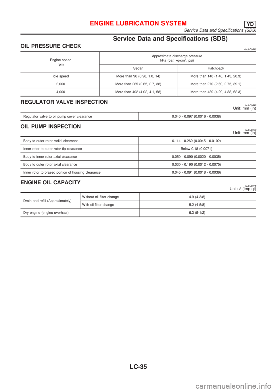
OIL PRESSURE CHECK=NJLC0048
Engine speed
rpmApproximate discharge pressure
kPa (bar, kg/cm2, psi)
Sedan Hatchback
Idle speed More than 98 (0.98, 1.0, 14) More than 140 (1.40, 1.43, 20.3)
2,000 More than 265 (2.65, 2.7, 38) More than 270 (2.69, 2.75, 39.1)
4,000 More than 402 (4.02, 4.1, 58) More than 430 (4.29, 4.38, 62.3)
REGULATOR VALVE INSPECTIONNJLC0049Unit: mm (in)
Regulator valve to oil pump cover clearance 0.040 - 0.097 (0.0016 - 0.0038)
OIL PUMP INSPECTIONNJLC0050Unit: mm (in)
Body to outer rotor radial clearance 0.114 - 0.260 (0.0045 - 0.0102)
Inner rotor to outer rotor tip clearance Below 0.18 (0.0071)
Body to inner rotor axial clearance 0.050 - 0.090 (0.0020 - 0.0035)
Body to outer rotor axial clearance 0.030 - 0.190 (0.0012 - 0.0075)
Inner rotor to brazed portion of housing clearance 0.045 - 0.091 (0.0018 - 0.0036)
ENGINE OIL CAPACITYNJLC0078Unit:!(Imp qt)
Drain and refill (Approximately)Without oil filter change 4.9 (4-3/8)
With oil filter change 5.2 (4-5/8)
Dry engine (engine overhaul)6.3 (5-1/2)
ENGINE LUBRICATION SYSTEMYD
Service Data and Specifications (SDS)
LC-35
Page 2542 of 2898

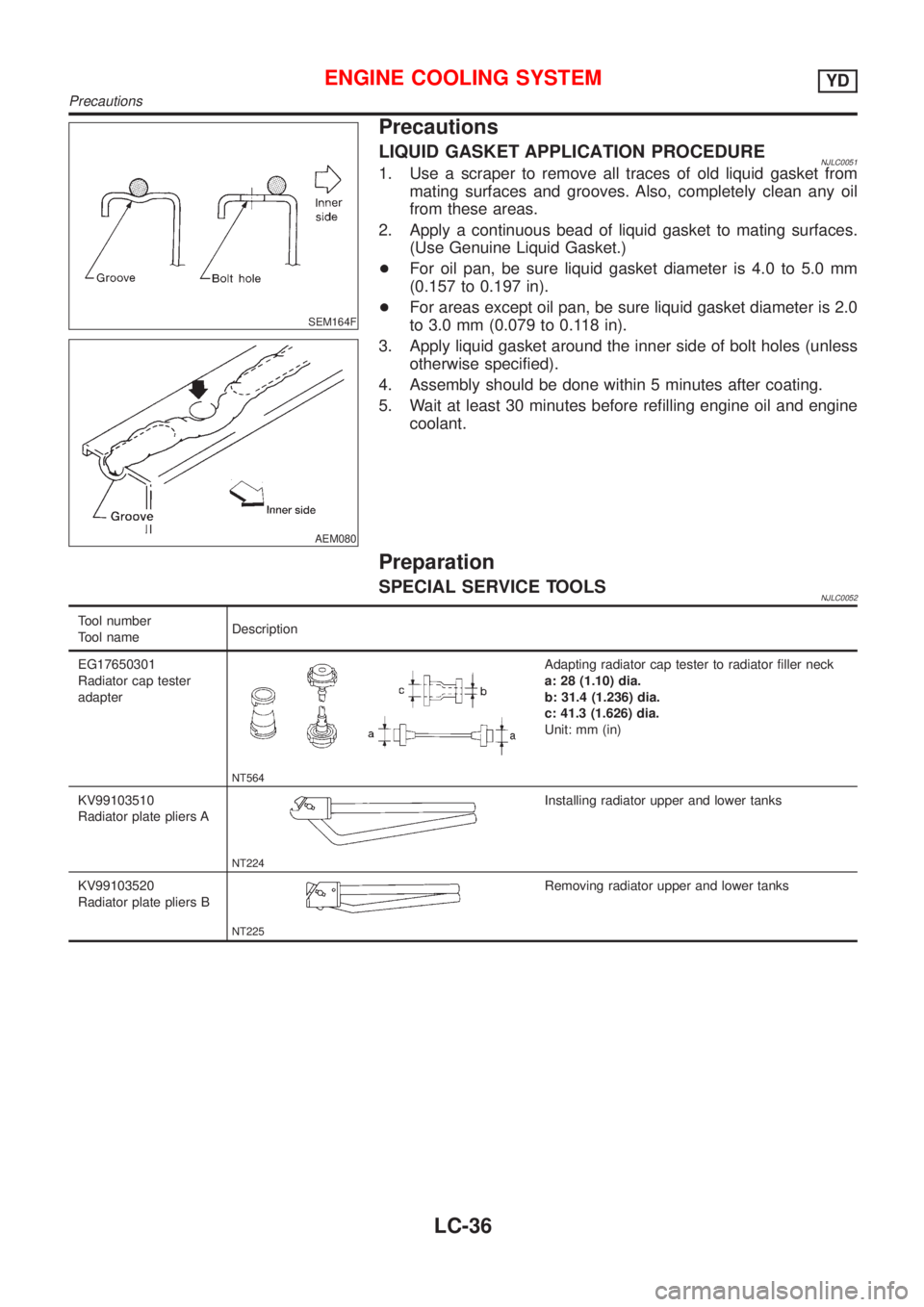
SEM164F
AEM080
Precautions
LIQUID GASKET APPLICATION PROCEDURENJLC00511. Use a scraper to remove all traces of old liquid gasket from
mating surfaces and grooves. Also, completely clean any oil
from these areas.
2. Apply a continuous bead of liquid gasket to mating surfaces.
(Use Genuine Liquid Gasket.)
+For oil pan, be sure liquid gasket diameter is 4.0 to 5.0 mm
(0.157 to 0.197 in).
+For areas except oil pan, be sure liquid gasket diameter is 2.0
to 3.0 mm (0.079 to 0.118 in).
3. Apply liquid gasket around the inner side of bolt holes (unless
otherwise specified).
4. Assembly should be done within 5 minutes after coating.
5. Wait at least 30 minutes before refilling engine oil and engine
coolant.
Preparation
SPECIAL SERVICE TOOLSNJLC0052
Tool number
Tool nameDescription
EG17650301
Radiator cap tester
adapter
NT564
Adapting radiator cap tester to radiator filler neck
a: 28 (1.10) dia.
b: 31.4 (1.236) dia.
c: 41.3 (1.626) dia.
Unit: mm (in)
KV99103510
Radiator plate pliers A
NT224
Installing radiator upper and lower tanks
KV99103520
Radiator plate pliers B
NT225
Removing radiator upper and lower tanks
ENGINE COOLING SYSTEMYD
Precautions
LC-36
Page 2546 of 2898
JLC294B
REMOVALNJLC00561. Remove the undercover, splash cover (right), and accessory
belt.
2. Drain engine coolant. Refer to LC-44, ªChanging Engine Cool-
antº.
3. Support the bottom of the oil pan with a floor jack etc., and
remove the right engine mount bracket (front side of the
engine).
4. Remove the water pump pulley.
+Loosen the pulley bolts after fixing the pulley using a screw-
driver etc.
5. Remove engine mount brackets.
6. Remove the water pump.
INSPECTIONNJLC0057+Check for rust and contamination adhering to the water pump
and vane.
+Turn the pump shaft by hand, and check that the pump turns
smoothly without looseness.
INSTALLATIONNJLC0058+Install the parts in the reverse order of removal.
+Install the water pump pulley with the front mark (painted white,
used to prevent errors during assembly) facing the front of the
engine. Refer to the figure above.
ENGINE COOLING SYSTEMYD
Water Pump (Cont'd)
LC-40
Page 2556 of 2898

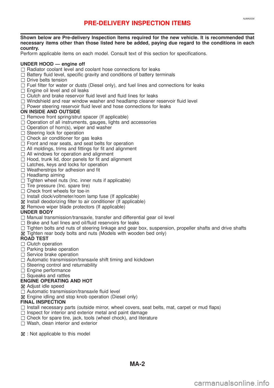
NJMA0036
Shown below are Pre-delivery Inspection Items required for the new vehicle. It is recommended that
necessary items other than those listed here be added, paying due regard to the conditions in each
country.
Perform applicable items on each model. Consult text of this section for specifications.
UNDER HOOD Ð engine off
Radiator coolant level and coolant hose connections for leaks
Battery fluid level, specific gravity and conditions of battery terminals
Drive belts tension
Fuel filter for water or dusts (Diesel only), and fuel lines and connections for leaks
Engine oil level and oil leaks
Clutch and brake reservoir fluid level and fluid lines for leaks
Windshield and rear window washer and headlamp cleaner reservoir fluid level
Power steering reservoir fluid level and hose connections for leaks
ON INSIDE AND OUTSIDE
Remove front spring/strut spacer (If applicable)
Operation of all instruments, gauges, lights and accessories
Operation of horn(s), wiper and washer
Steering lock for operation
Check air conditioner for gas leaks
Front and rear seats, and seat belts for operation
All moldings, trims and fittings for fit and alignment
All windows for operation and alignment
Hood, trunk lid, door panels for fit and alignment
Latches, keys and locks for operation
Weatherstrips for adhesion and fit
Headlamp aiming
Tighten wheel nuts (Inc. inner nuts if applicable)
Tire pressure (Inc. spare tire)
Check front wheels for toe-in
Install clock/voltmeter/room lamp fuse (If applicable)
Install deodorizing filter to air conditioner (If applicable)
Remove wiper blade protectors (If applicable)
UNDER BODY
Manual transmission/transaxle, transfer and differential gear oil level
Brake and fuel lines and oil/fluid reservoirs for leaks
Tighten bolts and nuts of steering linkage and gear box, suspension, propeller shafts and drive shafts
Tighten rear body bolts and nuts (Models with wooden bed only)
ROAD TEST
Clutch operation
Parking brake operation
Service brake operation
Automatic transmission/transaxle shift timing and kickdown
Steering control and returnability
Engine performance
Squeaks and rattles
ENGINE OPERATING AND HOT
Adjust idle speed
Automatic transmission/transaxle fluid level
Engine idling and stop knob operation (Diesel only)
FINAL INSPECTION
Install necessary parts (outside mirror, wheel covers, seat belts, mat, carpet or mud flaps)
Inspect for interior and exterior metal and paint damage
Check for spare tire, jack, tools (wheel chock), and literature
Wash, clean interior and exterior
: Not applicable to this model
PRE-DELIVERY INSPECTION ITEMS
MA-2