Page 2844 of 2898

Bleeding Hydraulic SystemNJST00141. Raise front end of vehicle until wheels are clear of the ground.
2. Add fluid into oil tank to specified level. Then quickly turn steer-
ing wheel fully to right and left and lightly touch steering stop-
pers.
Repeat steering wheel operation until fluid level no longer
decreases.
3. Start engine.
Repeat step 2. above.
+Incomplete air bleeding will cause the following to occur. When
this happens, bleed air again.
a) Air bubbles in reservoir tank
b) Clicking noise in oil pump
c) Excessive buzzing in oil pump
Fluid noise may occur in the valve or oil pump. This is common
when the vehicle is stationary or while turning the steering wheel
slowly. This does not affect the performance or durability of the
system.
SST491B
SST090B
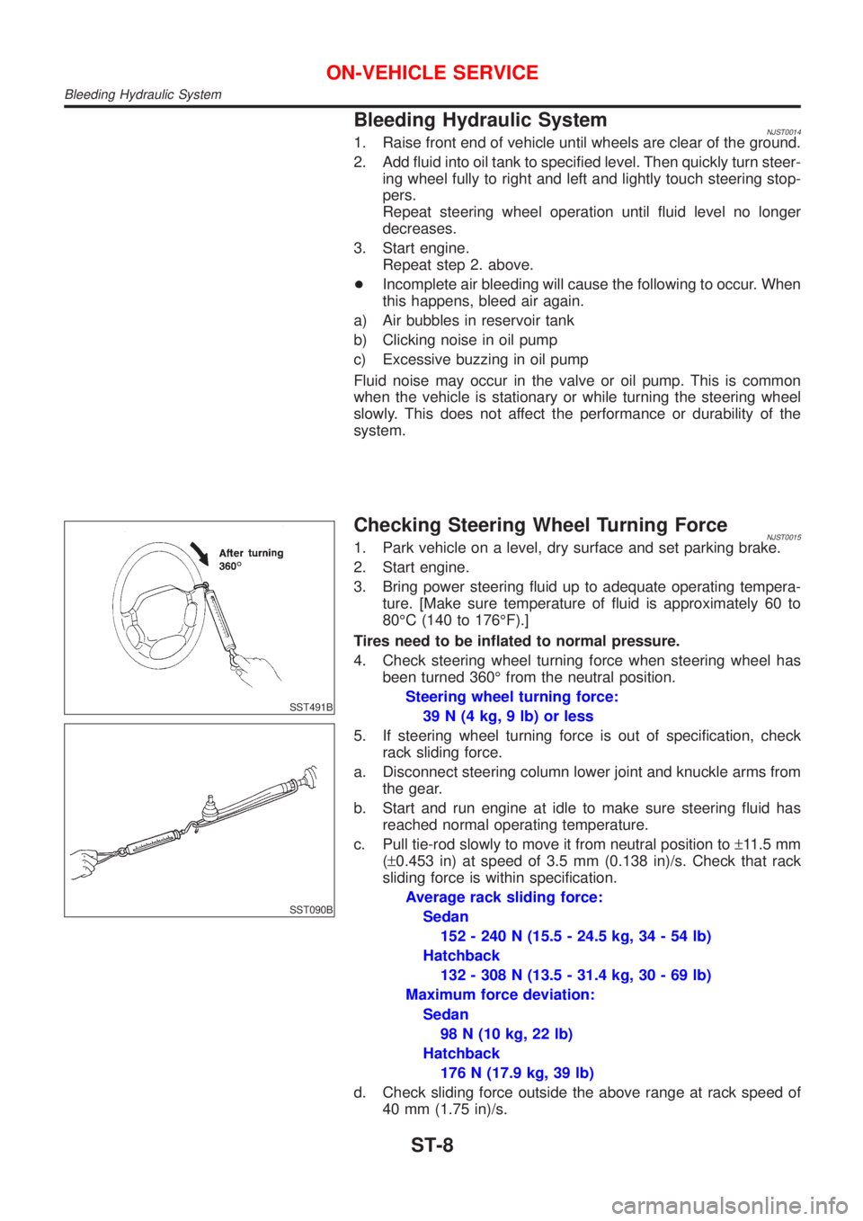
Checking Steering Wheel Turning ForceNJST00151. Park vehicle on a level, dry surface and set parking brake.
2. Start engine.
3. Bring power steering fluid up to adequate operating tempera-
ture. [Make sure temperature of fluid is approximately 60 to
80ÉC (140 to 176ÉF).]
Tires need to be inflated to normal pressure.
4. Check steering wheel turning force when steering wheel has
been turned 360É from the neutral position.
Steering wheel turning force:
39 N (4 kg, 9 lb) or less
5. If steering wheel turning force is out of specification, check
rack sliding force.
a. Disconnect steering column lower joint and knuckle arms from
the gear.
b. Start and run engine at idle to make sure steering fluid has
reached normal operating temperature.
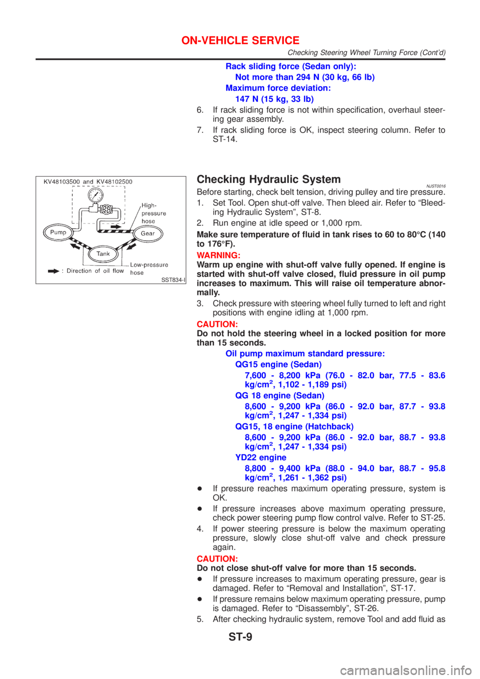
c. Pull tie-rod slowly to move it from neutral position to±11.5 mm
(±0.453 in) at speed of 3.5 mm (0.138 in)/s. Check that rack
sliding force is within specification.
Average rack sliding force:
Sedan
152 - 240 N (15.5 - 24.5 kg, 34 - 54 lb)
Hatchback
132 - 308 N (13.5 - 31.4 kg, 30 - 69 lb)
Maximum force deviation:
Sedan
98 N (10 kg, 22 lb)
Hatchback
176 N (17.9 kg, 39 lb)
d. Check sliding force outside the above range at rack speed of
40 mm (1.75 in)/s.
ON-VEHICLE SERVICE
Bleeding Hydraulic System
ST-8
Page 2845 of 2898

Rack sliding force (Sedan only):
Not more than 294 N (30 kg, 66 lb)
Maximum force deviation:
147 N (15 kg, 33 lb)
6. If rack sliding force is not within specification, overhaul steer-
ing gear assembly.
7. If rack sliding force is OK, inspect steering column. Refer to
ST-14.
SST834-I
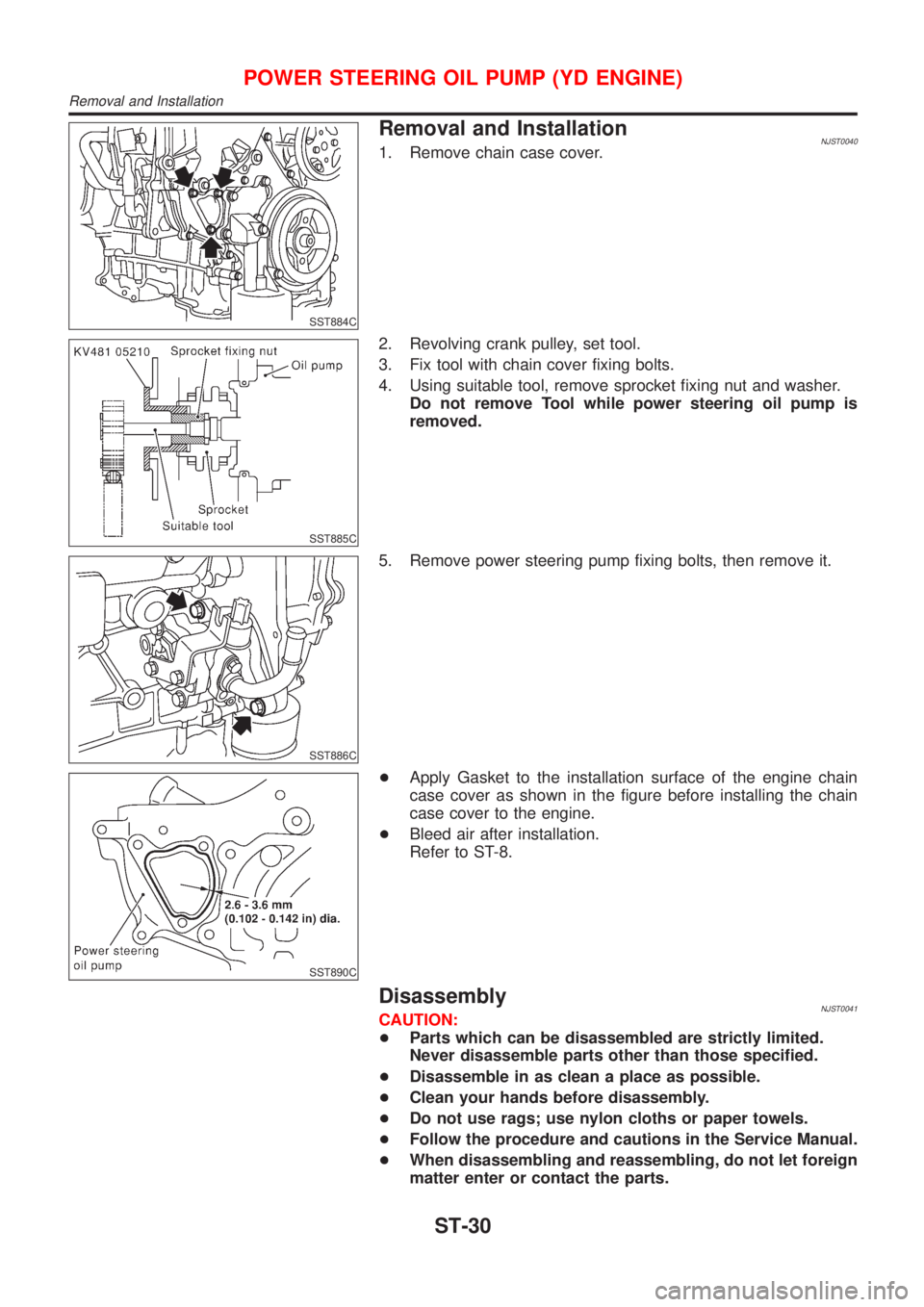
Checking Hydraulic SystemNJST0016Before starting, check belt tension, driving pulley and tire pressure.
1. Set Tool. Open shut-off valve. Then bleed air. Refer to ªBleed-
ing Hydraulic Systemº, ST-8.
2. Run engine at idle speed or 1,000 rpm.
Make sure temperature of fluid in tank rises to 60 to 80ÉC (140
to 176ÉF).
WARNING:
Warm up engine with shut-off valve fully opened. If engine is
started with shut-off valve closed, fluid pressure in oil pump
increases to maximum. This will raise oil temperature abnor-
mally.
3. Check pressure with steering wheel fully turned to left and right
positions with engine idling at 1,000 rpm.
CAUTION:
Do not hold the steering wheel in a locked position for more
than 15 seconds.
Oil pump maximum standard pressure:
QG15 engine (Sedan)
7,600 - 8,200 kPa (76.0 - 82.0 bar, 77.5 - 83.6
kg/cm
2, 1,102 - 1,189 psi)
QG 18 engine (Sedan)
8,600 - 9,200 kPa (86.0 - 92.0 bar, 87.7 - 93.8
kg/cm
2, 1,247 - 1,334 psi)
QG15, 18 engine (Hatchback)
8,600 - 9,200 kPa (86.0 - 92.0 bar, 88.7 - 93.8
kg/cm
2, 1,247 - 1,334 psi)
YD22 engine
8,800 - 9,400 kPa (88.0 - 94.0 bar, 88.7 - 95.8
kg/cm
2, 1,261 - 1,362 psi)
+If pressure reaches maximum operating pressure, system is
OK.
+If pressure increases above maximum operating pressure,
check power steering pump flow control valve. Refer to ST-25.
4. If power steering pressure is below the maximum operating
pressure, slowly close shut-off valve and check pressure
again.
CAUTION:
Do not close shut-off valve for more than 15 seconds.
+If pressure increases to maximum operating pressure, gear is
damaged. Refer to ªRemoval and Installationº, ST-17.
+If pressure remains below maximum operating pressure, pump
is damaged. Refer to ªDisassemblyº, ST-26.
5. After checking hydraulic system, remove Tool and add fluid as
ON-VEHICLE SERVICE
Checking Steering Wheel Turning Force (Cont'd)
ST-9
Page 2861 of 2898
ComponentsNJST0027
SST881CA
1. Pulley
2. Bracket
3. Drive shaft seal
4. Inlet connector
5. Inlet connector seal
6. Front housing
7. Flow control valve spring8. Flow control A valve
9. Dowel pin
10. Flow control B valve assy
11. Front side plate
12. Cartridge
13. Rotor
14. Vane15. Rotor snap ring
16. Rear side plate
17. Side plate inner seal
18. Side plate outer seal
19. Body seal
20. Rear body
SST984A
Pre-disassembly InspectionNJST0028Disassemble the power steering oil pump only if the following items
are found.
+Oil leak from any point shown in the figure
+Deformed or damaged pulley
+Poor performance
POWER STEERING OIL PUMP (QG ENGINE)
Components
ST-25
Page 2862 of 2898
DisassemblyNJST0029CAUTION:
+The power steering pump cannot be disassembled on
Hatchback with QG engine. If it is faulty, replae with a new
assembly.
+Parts which can be disassembled are strictly limited.
Never disassemble parts other than those specified.
+Disassemble in as clean a place as possible.
+Clean your hands before disassembly.
+Do not use rags; use nylon cloths or paper towels.
+Follow the procedures and cautions in the Service
Manual.
+When disassembling and reassembling, do not let foreign
matter enter or contact the parts.
SST010B
+Remove snap ring, then draw drive shaft out.
Be careful not to drop drive shaft.
SST034A
+Remove oil seal.
Be careful not to damage front housing.
SST036A
+Remove connector and flow control valve with spring.
Be careful not to drop flow control valve.
Do not disassemble flow control valve.
POWER STEERING OIL PUMP (QG ENGINE)
Disassembly
ST-26
Page 2863 of 2898
InspectionNJST0030+If pulley is cracked or deformed, replace it.
+If an oil leak is found around pulley shaft oil seal, replace the
seal.
+If serration on pulley or pulley shaft is deformed or worn,
replace it.
SST038A
AssemblyNJST0031Assemble oil pump, noting the following instructions.
+Make sure O-rings and oil seal are properly installed.
+Always install new O-rings and oil seal.
+Be careful of oil seal direction.
+Cam ring, rotor and vanes must be replaced as a set if neces-
sary.
+Coat each part with DEXRON
TMIII or equivalent when assem-
bling.
SST289A
+Pay attention to the direction of rotor.
SST843A
+When assembling vanes to rotor, rounded surfaces of vanes
must face cam ring side.
POWER STEERING OIL PUMP (QG ENGINE)
Inspection
ST-27
Page 2864 of 2898
SST472C
+Insert pin 2 into pin groove 1 of front housing and front side
plate. Then install cam ring 3 as shown at left.
Cam ring:
D
1is less than D2.
POWER STEERING OIL PUMP (QG ENGINE)
Assembly (Cont'd)
ST-28
Page 2865 of 2898
ComponentsNJST0038
SST882CA
1. Rear bracket
2. Rear body
3. Dowel pin
4. Side plate seal
5. Cam ring
6. Vane
7. Rotor
8. Side plate9. O-ring (Outer)
10. O-ring (Inner)
11. Front body
12. Drive shaft rear oil seal
13. Drive shaft front oil seal
14. Drive shaft
15. Snap ring
16. O-ring17. Outlet connector
18. Connector seal
19. Flow control valve
20. Flow control valve spring
21. Inlet connector
22. O-ring
23. Washer
SST883C
Pre-disassembly InspectionNJST0039Disassemble the power steering oil pump only if the following items
are found.
+Oil leak from any point shown in the figure
+Poor performance
POWER STEERING OIL PUMP (YD ENGINE)
Components
ST-29
Page 2866 of 2898

SST884C
Removal and InstallationNJST00401. Remove chain case cover.
SST885C
2. Revolving crank pulley, set tool.
3. Fix tool with chain cover fixing bolts.
4. Using suitable tool, remove sprocket fixing nut and washer.
Do not remove Tool while power steering oil pump is
removed.
SST886C
5. Remove power steering pump fixing bolts, then remove it.
SST890C
+Apply Gasket to the installation surface of the engine chain
case cover as shown in the figure before installing the chain
case cover to the engine.
+Bleed air after installation.
Refer to ST-8.
DisassemblyNJST0041CAUTION:
+Parts which can be disassembled are strictly limited.
Never disassemble parts other than those specified.
+Disassemble in as clean a place as possible.
+Clean your hands before disassembly.
+Do not use rags; use nylon cloths or paper towels.
+Follow the procedure and cautions in the Service Manual.
+When disassembling and reassembling, do not let foreign
matter enter or contact the parts.
POWER STEERING OIL PUMP (YD ENGINE)
Removal and Installation
ST-30