2001 NISSAN ALMERA engine oil
[x] Cancel search: engine oilPage 2598 of 2898
NJMT0090
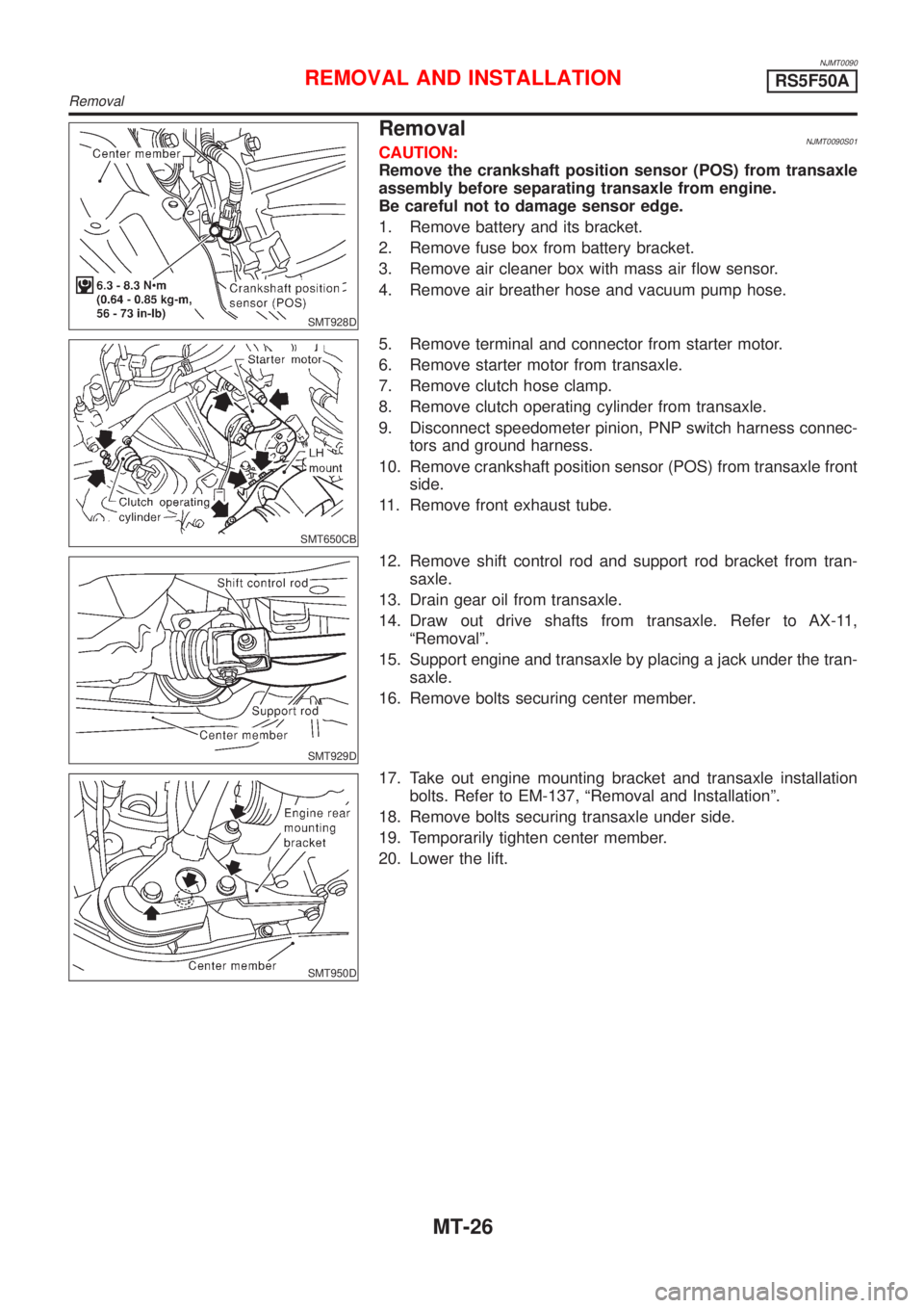
SMT928D
RemovalNJMT0090S01CAUTION:
Remove the crankshaft position sensor (POS) from transaxle
assembly before separating transaxle from engine.
Be careful not to damage sensor edge.
1. Remove battery and its bracket.
2. Remove fuse box from battery bracket.
3. Remove air cleaner box with mass air flow sensor.
4. Remove air breather hose and vacuum pump hose.
SMT650CB
5. Remove terminal and connector from starter motor.
6. Remove starter motor from transaxle.
7. Remove clutch hose clamp.
8. Remove clutch operating cylinder from transaxle.
9. Disconnect speedometer pinion, PNP switch harness connec-
tors and ground harness.
10. Remove crankshaft position sensor (POS) from transaxle front
side.
11. Remove front exhaust tube.
SMT929D
12. Remove shift control rod and support rod bracket from tran-
saxle.
13. Drain gear oil from transaxle.
14. Draw out drive shafts from transaxle. Refer to AX-11,
ªRemovalº.
15. Support engine and transaxle by placing a jack under the tran-
saxle.
16. Remove bolts securing center member.
SMT950D
17. Take out engine mounting bracket and transaxle installation
bolts. Refer to EM-137, ªRemoval and Installationº.
18. Remove bolts securing transaxle under side.
19. Temporarily tighten center member.
20. Lower the lift.
REMOVAL AND INSTALLATIONRS5F50A
Removal
MT-26
Page 2599 of 2898
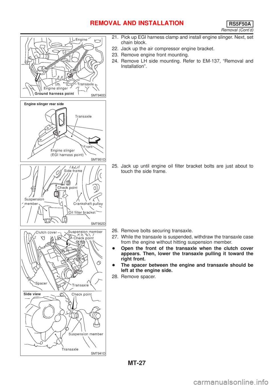
SMT940D
SMT951D
21. Pick up EGI harness clamp and install engine slinger. Next, set
chain block.
22. Jack up the air compressor engine bracket.
23. Remove engine front mounting.
24. Remove LH side mounting. Refer to EM-137, ªRemoval and
Installationº.
SMT952D
25. Jack up until engine oil filter bracket bolts are just about to
touch the side frame.
SMT941D
26. Remove bolts securing transaxle.
27. While the transaxle is suspended, withdraw the transaxle case
from the engine without hitting suspension member.
+Open the front of the transaxle when the clutch cover
appears. Then, lower the transaxle pulling it toward the
right front.
+The spacer between the engine and transaxle should be
left at the engine side.
28. Remove spacer.
REMOVAL AND INSTALLATIONRS5F50A
Removal (Cont'd)
MT-27
Page 2690 of 2898
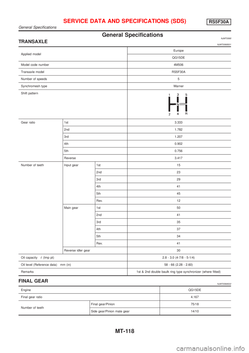
General SpecificationsNJMT0068TRANSAXLENJMT0068S01
Applied modelEurope
QG15DE
Model code number4M506
Transaxle modelRS5F30A
Number of speeds5
Synchromesh typeWarner
Shift pattern
Gear ratio 1st3.333
2nd1.782
3rd1.207
4th0.902
5th0.756
Reverse 3.417
Number of teeth Input gear 1st 15
2nd 23
3rd 29
4th 41
5th 45
Rev. 12
Main gear 1st 50
2nd 41
3rd 35
4th 37
5th 34
Rev. 41
Reverse idler gear 30
Oil capacity!(Imp pt)2.8 - 3.0 (4-7/8 - 5-1/4)
Oil level (Reference data) mm (in) 58 - 66 (2.28 - 2.60)
Remarks1st & 2nd double baulk ring type synchronizer (where fitted)
FINAL GEARNJMT0068S02
EngineQG15DE
Final gear ratio4.167
Number of teethFinal gear/Pinion 75/18
Side gear/Pinion mate gear 14/10
SERVICE DATA AND SPECIFICATIONS (SDS)RS5F30A
General Specifications
MT-118
Page 2695 of 2898
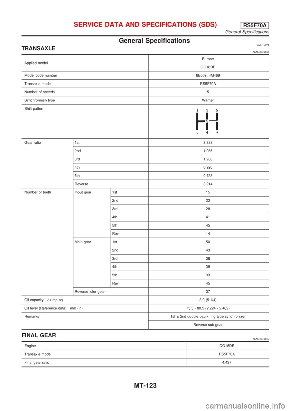
General SpecificationsNJMT0076TRANSAXLENJMT0076S01
Applied modelEurope
QG18DE
Model code number8E009, 4M469
Transaxle modelRS5F70A
Number of speeds5
Synchromesh typeWarner
Shift pattern
Gear ratio 1st3.333
2nd1.955
3rd1.286
4th0.926
5th0.733
Reverse 3.214
Number of teeth Input gear 1st 15
2nd 22
3rd 28
4th 41
5th 45
Rev. 14
Main gear 1st 50
2nd 43
3rd 36
4th 38
5th 33
Rev. 45
Reverse idler gear 37
Oil capacity!(Imp pt)3.0 (5-1/4)
Oil level (Reference data) mm (in) 75.5 - 80.5 (2.224 - 2.402)
Remarks1st & 2nd double baulk ring type synchronizer
Reverse sub-gear
FINAL GEARNJMT0076S02
EngineQG18DE
Transaxle modelRS5F70A
Final gear ratio4.437
SERVICE DATA AND SPECIFICATIONS (SDS)RS5F70A
General Specifications
MT-123
Page 2703 of 2898
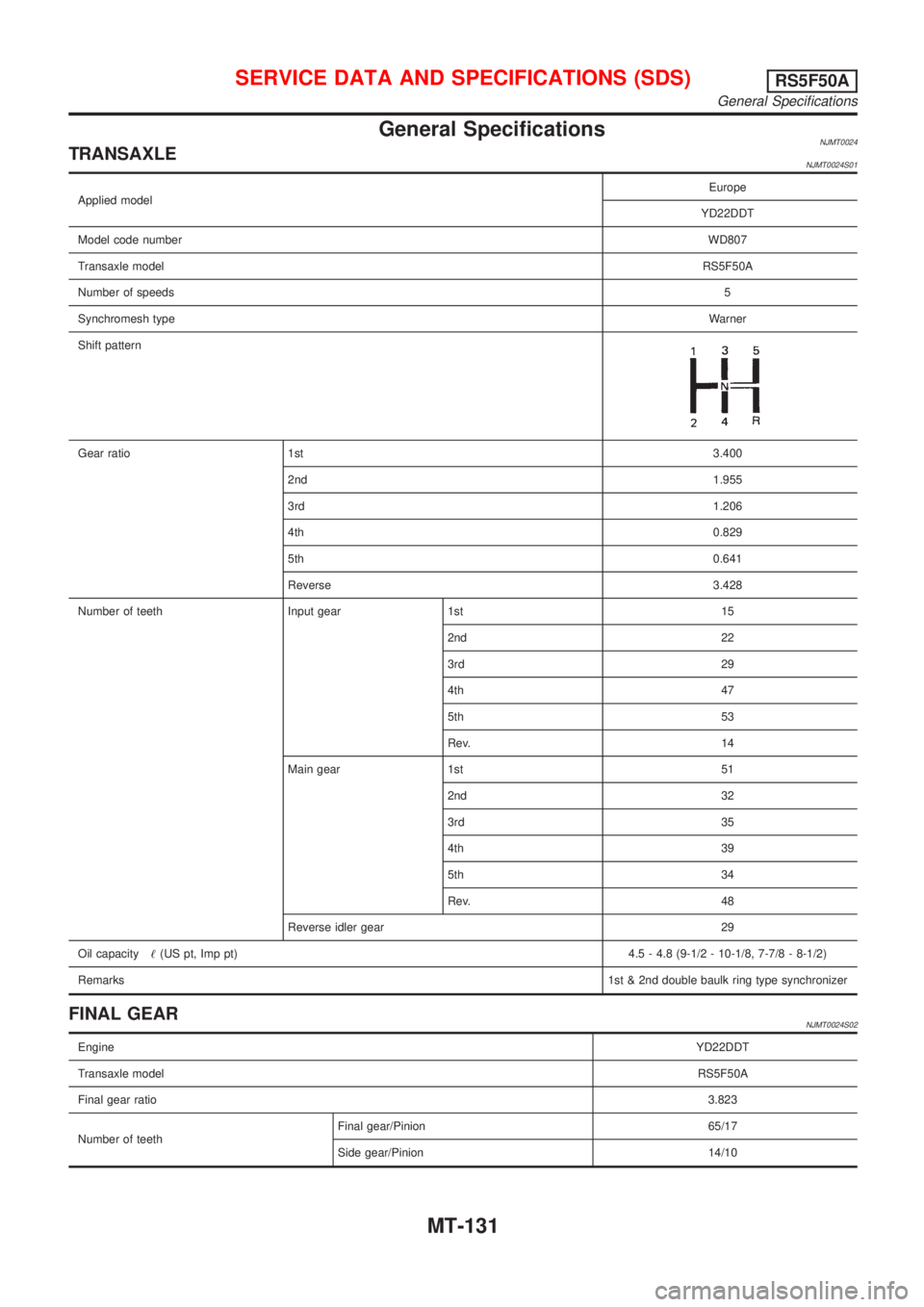
General SpecificationsNJMT0024TRANSAXLENJMT0024S01
Applied modelEurope
YD22DDT
Model code numberWD807
Transaxle modelRS5F50A
Number of speeds5
Synchromesh typeWarner
Shift pattern
Gear ratio 1st3.400
2nd1.955
3rd1.206
4th0.829
5th0.641
Reverse3.428
Number of teeth Input gear 1st 15
2nd 22
3rd 29
4th 47
5th 53
Rev. 14
Main gear 1st 51
2nd 32
3rd 35
4th 39
5th 34
Rev. 48
Reverse idler gear 29
Oil capacity!(US pt, Imp pt)4.5 - 4.8 (9-1/2 - 10-1/8, 7-7/8 - 8-1/2)
Remarks1st & 2nd double baulk ring type synchronizer
FINAL GEARNJMT0024S02
EngineYD22DDT
Transaxle modelRS5F50A
Final gear ratio3.823
Number of teethFinal gear/Pinion 65/17
Side gear/Pinion 14/10
SERVICE DATA AND SPECIFICATIONS (SDS)RS5F50A
General Specifications
MT-131
Page 2835 of 2898
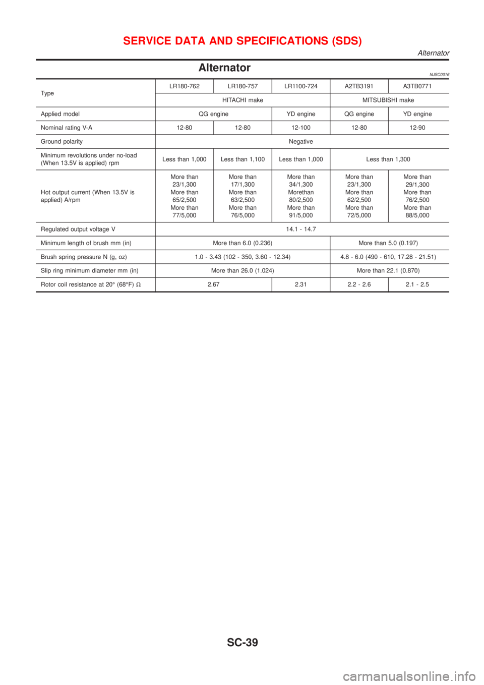
AlternatorNJSC0016
TypeLR180-762 LR180-757 LR1100-724 A2TB3191 A3TB0771
HITACHI make MITSUBISHI make
Applied model QG engine YD engine QG engine YD engine
Nominal rating V-A 12-80 12-80 12-100 12-80 12-90
Ground polarityNegative
Minimum revolutions under no-load
(When 13.5V is applied) rpmLess than 1,000 Less than 1,100 Less than 1,000 Less than 1,300
Hot output current (When 13.5V is
applied) A/rpmMore than
23/1,300
More than
65/2,500
More than
77/5,000More than
17/1,300
More than
63/2,500
More than
76/5,000More than
34/1,300
Morethan
80/2,500
More than
91/5,000More than
23/1,300
More than
62/2,500
More than
72/5,000More than
29/1,300
More than
76/2,500
More than
88/5,000
Regulated output voltage V 14.1 - 14.7
Minimum length of brush mm (in) More than 6.0 (0.236) More than 5.0 (0.197)
Brush spring pressure N (g, oz) 1.0 - 3.43 (102 - 350, 3.60 - 12.34) 4.8 - 6.0 (490 - 610, 17.28 - 21.51)
Slip ring minimum diameter mm (in) More than 26.0 (1.024) More than 22.1 (0.870)
Rotor coil resistance at 20É (68ÉF)W2.67 2.31 2.2 - 2.6 2.1 - 2.5
SERVICE DATA AND SPECIFICATIONS (SDS)
Alternator
SC-39
Page 2837 of 2898
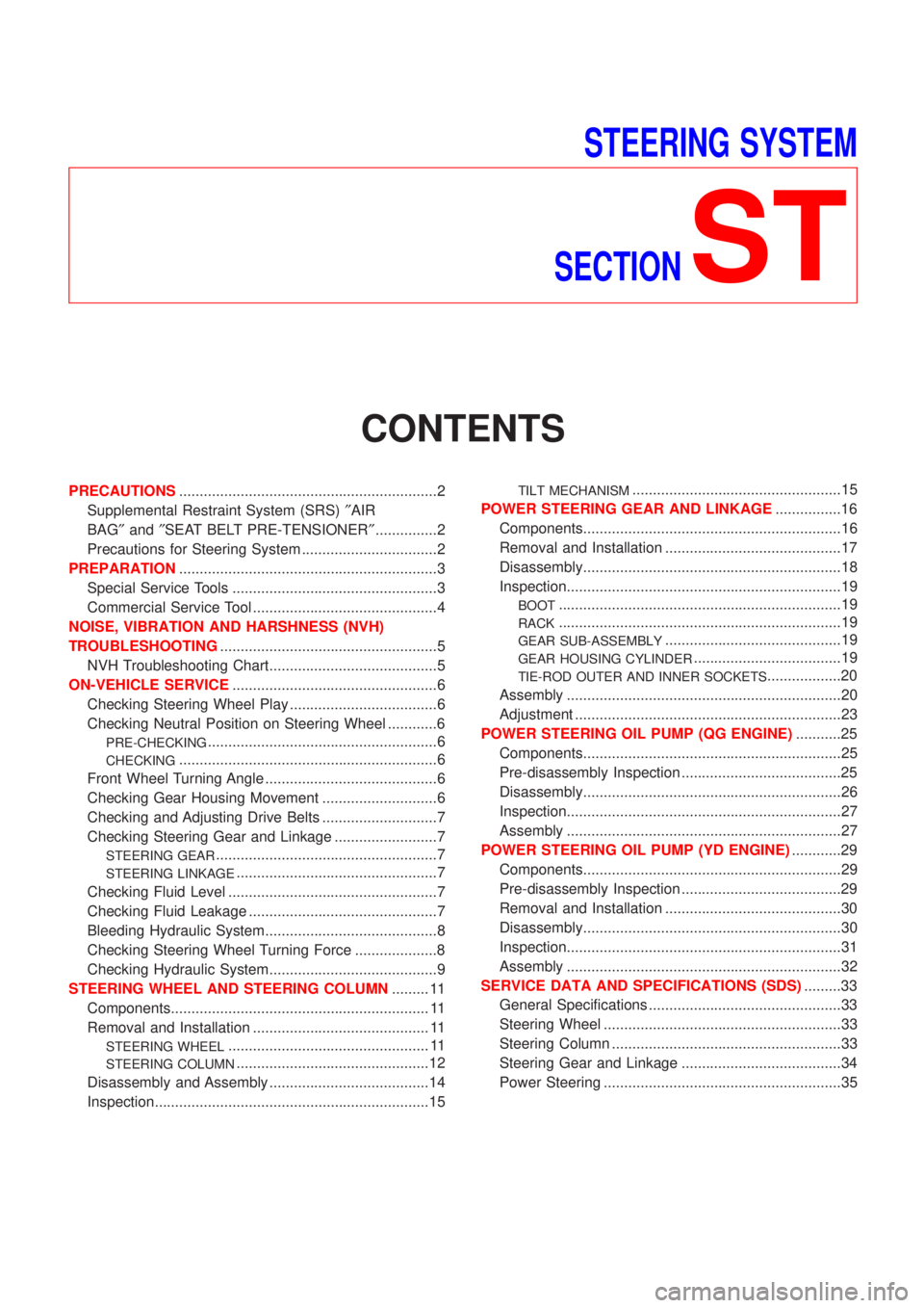
STEERING SYSTEM
SECTION
ST
CONTENTS
PRECAUTIONS...............................................................2
Supplemental Restraint System (SRS)²AIR
BAG²and²SEAT BELT PRE-TENSIONER²...............2
Precautions for Steering System .................................2
PREPARATION...............................................................3
Special Service Tools ..................................................3
Commercial Service Tool .............................................4
NOISE, VIBRATION AND HARSHNESS (NVH)
TROUBLESHOOTING.....................................................5
NVH Troubleshooting Chart.........................................5
ON-VEHICLE SERVICE..................................................6
Checking Steering Wheel Play ....................................6
Checking Neutral Position on Steering Wheel ............6
PRE-CHECKING........................................................6
CHECKING...............................................................6
Front Wheel Turning Angle ..........................................6
Checking Gear Housing Movement ............................6
Checking and Adjusting Drive Belts ............................7
Checking Steering Gear and Linkage .........................7
STEERING GEAR......................................................7
STEERING LINKAGE.................................................7
Checking Fluid Level ...................................................7
Checking Fluid Leakage ..............................................7
Bleeding Hydraulic System..........................................8
Checking Steering Wheel Turning Force ....................8
Checking Hydraulic System.........................................9
STEERING WHEEL AND STEERING COLUMN......... 11
Components............................................................... 11
Removal and Installation ........................................... 11
STEERING WHEEL................................................. 11
STEERING COLUMN...............................................12
Disassembly and Assembly .......................................14
Inspection...................................................................15
TILT MECHANISM...................................................15
POWER STEERING GEAR AND LINKAGE................16
Components...............................................................16
Removal and Installation ...........................................17
Disassembly...............................................................18
Inspection...................................................................19
BOOT.....................................................................19
RACK.....................................................................19
GEAR SUB-ASSEMBLY...........................................19
GEAR HOUSING CYLINDER....................................19
TIE-ROD OUTER AND INNER SOCKETS..................20
Assembly ...................................................................20
Adjustment .................................................................23
POWER STEERING OIL PUMP (QG ENGINE)...........25
Components...............................................................25
Pre-disassembly Inspection .......................................25
Disassembly...............................................................26
Inspection...................................................................27
Assembly ...................................................................27
POWER STEERING OIL PUMP (YD ENGINE)............29
Components...............................................................29
Pre-disassembly Inspection .......................................29
Removal and Installation ...........................................30
Disassembly...............................................................30
Inspection...................................................................31
Assembly ...................................................................32
SERVICE DATA AND SPECIFICATIONS (SDS).........33
General Specifications ...............................................33
Steering Wheel ..........................................................33
Steering Column ........................................................33
Steering Gear and Linkage .......................................34
Power Steering ..........................................................35
Page 2843 of 2898
Checking and Adjusting Drive BeltsNJST0011Refer to EM-16, ªChecking Drive Beltsº.
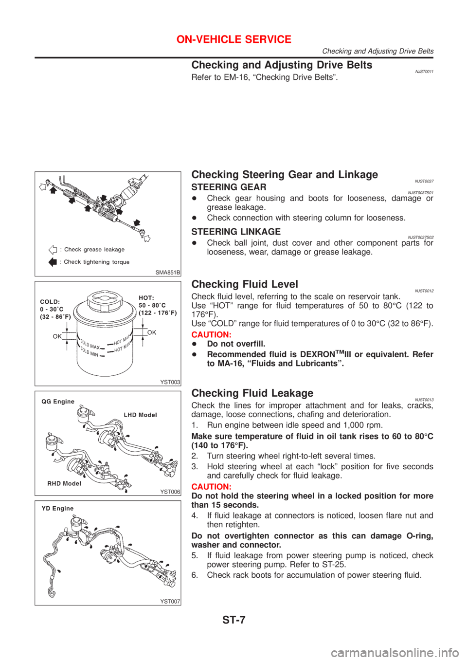
SMA851B
Checking Steering Gear and LinkageNJST0037STEERING GEARNJST0037S01+Check gear housing and boots for looseness, damage or
grease leakage.
+Check connection with steering column for looseness.
STEERING LINKAGENJST0037S02+Check ball joint, dust cover and other component parts for
looseness, wear, damage or grease leakage.
YST003
Checking Fluid LevelNJST0012Check fluid level, referring to the scale on reservoir tank.
Use ªHOTº range for fluid temperatures of 50 to 80ÉC (122 to
176ÉF).
Use ªCOLDº range for fluid temperatures of 0 to 30ÉC (32 to 86ÉF).
CAUTION:
+Do not overfill.
+Recommended fluid is DEXRON
TMIII or equivalent. Refer
to MA-16, ªFluids and Lubricantsº.
YST006
YST007
Checking Fluid LeakageNJST0013Check the lines for improper attachment and for leaks, cracks,
damage, loose connections, chafing and deterioration.
1. Run engine between idle speed and 1,000 rpm.
Make sure temperature of fluid in oil tank rises to 60 to 80ÉC
(140 to 176ÉF).
2. Turn steering wheel right-to-left several times.
3. Hold steering wheel at each ªlockº position for five seconds
and carefully check for fluid leakage.
CAUTION:
Do not hold the steering wheel in a locked position for more
than 15 seconds.
4. If fluid leakage at connectors is noticed, loosen flare nut and
then retighten.
Do not overtighten connector as this can damage O-ring,
washer and connector.
5. If fluid leakage from power steering pump is noticed, check
power steering pump. Refer to ST-25.
6. Check rack boots for accumulation of power steering fluid.
ON-VEHICLE SERVICE
Checking and Adjusting Drive Belts
ST-7