Page 229 of 2493

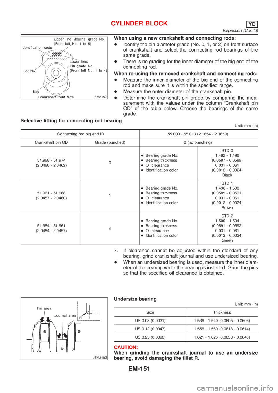
JEM215G
When using a new crankshaft and connecting rods:
+Identify the pin diameter grade (No. 0, 1, or 2) on front surface
of crankshaft and select the connecting rod bearings of the
same grade.
+There is no grading for the inner diameter of the big end of the
connecting rod.
When re-using the removed crankshaft and connecting rods:
+Measure the inner diameter of the big end of the connecting
rod and make sure it is within the specified range.
+Measure the outer diameter of the crankshaft pin.
+Determine the crankshaft pin grade by comparing the mea-
surement with the values under the column ªCrankshaft pin
ODº of the table below. Choose the bearings of the same
grade.
Selective fitting for connecting rod bearing
Unit: mm (in)
Connecting rod big end ID 55.000 - 55.013 (2.1654 - 2.1659)
Crankshaft pin OD Grade (punched) 0 (no punching)
51.968 - 51.974
(2.0460 - 2.0462)0+Bearing grade No.
+Bearing thickness
+Oil clearance
+Identification colorSTD 0
1.492 - 1.496
(0.0587 - 0.0589)
0.031 - 0.061
(0.0012 - 0.0024)
Black
51.961 - 51.968
(2.0457 - 2.0460)1+Bearing grade No.
+Bearing thickness
+Oil clearance
+Identification colorSTD 1
1.496 - 1.500
(0.0589 - 0.0591)
0.031 - 0.061
(0.0012 - 0.0024)
Brown
51.954 - 51.961
(2.0454 - 2.0457)2+Bearing grade No.
+Bearing thickness
+Oil clearance
+Identification colorSTD 2
1.500 - 1.504
(0.0591 - 0.0592)
0.031 - 0.061
(0.0012 - 0.0024)
Green
7. If clearance cannot be adjusted within the standard of any
bearing, grind crankshaft journal and use undersized bearing.
+When an undersized bearing is used, measure the inner diam-
eter of the bearing while the bearing is installed. Grind the pins
so that the specified oil clearance is obtained.
JEM216G
Undersize bearing
Unit: mm (in)
Size Thickness
US 0.08 (0.0031) 1.536 - 1.540 (0.0605 - 0.0606)
US 0.12 (0.0047) 1.556 - 1.560 (0.0613 - 0.0614)
US 0.25 (0.0098) 1.621 - 1.625 (0.0638 - 0.0640)
CAUTION:
When grinding the crankshaft journal to use an undersize
bearing, avoid damaging the fillet R.
CYLINDER BLOCKYD
Inspection (Cont'd)
EM-151
Page 230 of 2493

Standard dimension R:
1.5 - 1.7 mm (0.0591 - 0.0669 in)
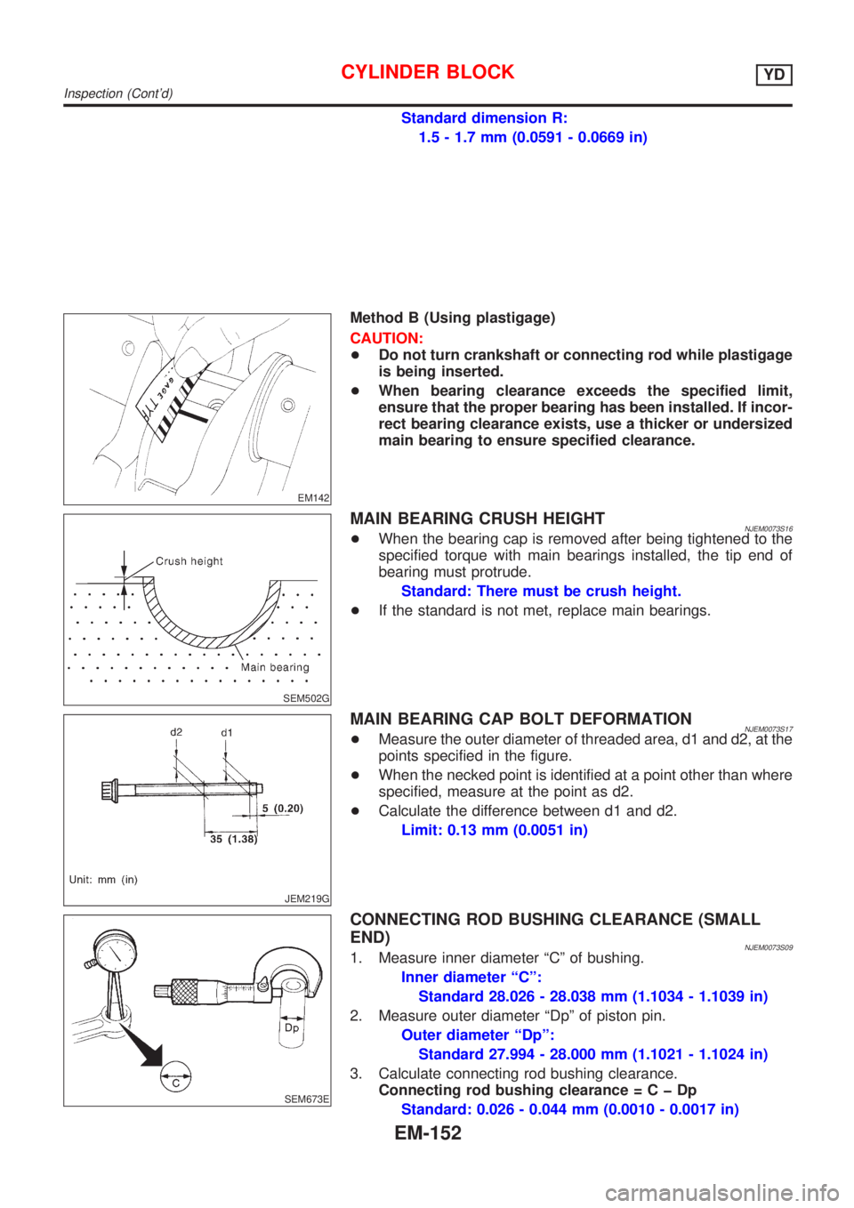
EM142
Method B (Using plastigage)
CAUTION:
+Do not turn crankshaft or connecting rod while plastigage
is being inserted.
+When bearing clearance exceeds the specified limit,
ensure that the proper bearing has been installed. If incor-
rect bearing clearance exists, use a thicker or undersized
main bearing to ensure specified clearance.
SEM502G
MAIN BEARING CRUSH HEIGHTNJEM0073S16+When the bearing cap is removed after being tightened to the
specified torque with main bearings installed, the tip end of
bearing must protrude.
Standard: There must be crush height.
+If the standard is not met, replace main bearings.
JEM219G
MAIN BEARING CAP BOLT DEFORMATIONNJEM0073S17+Measure the outer diameter of threaded area, d1 and d2, at the
points specified in the figure.
+When the necked point is identified at a point other than where
specified, measure at the point as d2.
+Calculate the difference between d1 and d2.
Limit: 0.13 mm (0.0051 in)
SEM673E
CONNECTING ROD BUSHING CLEARANCE (SMALL
END)
NJEM0073S091. Measure inner diameter ªCº of bushing.
Inner diameter ªCº:
Standard 28.026 - 28.038 mm (1.1034 - 1.1039 in)
2. Measure outer diameter ªDpº of piston pin.
Outer diameter ªDpº:
Standard 27.994 - 28.000 mm (1.1021 - 1.1024 in)
3. Calculate connecting rod bushing clearance.
Connecting rod bushing clearance=CþDp
Standard: 0.026 - 0.044 mm (0.0010 - 0.0017 in)
CYLINDER BLOCKYD
Inspection (Cont'd)
EM-152
Page 233 of 2493

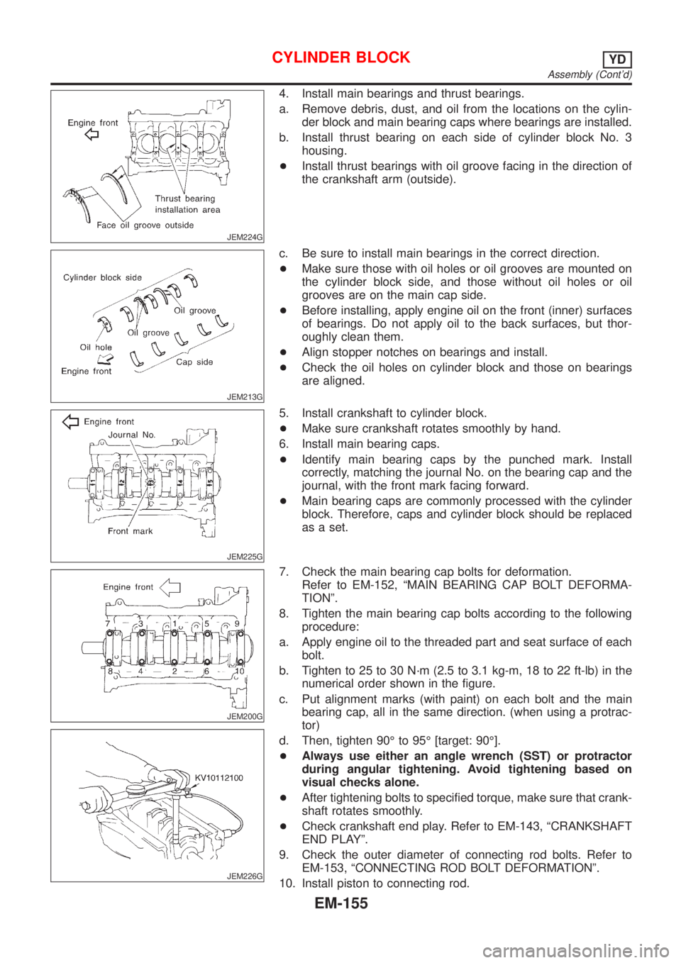
JEM224G
4. Install main bearings and thrust bearings.
a. Remove debris, dust, and oil from the locations on the cylin-
der block and main bearing caps where bearings are installed.
b. Install thrust bearing on each side of cylinder block No. 3
housing.
+Install thrust bearings with oil groove facing in the direction of
the crankshaft arm (outside).
JEM213G
c. Be sure to install main bearings in the correct direction.
+Make sure those with oil holes or oil grooves are mounted on
the cylinder block side, and those without oil holes or oil
grooves are on the main cap side.
+Before installing, apply engine oil on the front (inner) surfaces
of bearings. Do not apply oil to the back surfaces, but thor-
oughly clean them.
+Align stopper notches on bearings and install.
+Check the oil holes on cylinder block and those on bearings
are aligned.
JEM225G
5. Install crankshaft to cylinder block.
+Make sure crankshaft rotates smoothly by hand.
6. Install main bearing caps.
+Identify main bearing caps by the punched mark. Install
correctly, matching the journal No. on the bearing cap and the
journal, with the front mark facing forward.
+Main bearing caps are commonly processed with the cylinder
block. Therefore, caps and cylinder block should be replaced
as a set.
JEM200G
JEM226G
7. Check the main bearing cap bolts for deformation.
Refer to EM-152, ªMAIN BEARING CAP BOLT DEFORMA-
TIONº.
8. Tighten the main bearing cap bolts according to the following
procedure:
a. Apply engine oil to the threaded part and seat surface of each
bolt.
b. Tighten to 25 to 30 N´m (2.5 to 3.1 kg-m, 18 to 22 ft-lb) in the
numerical order shown in the figure.
c. Put alignment marks (with paint) on each bolt and the main
bearing cap, all in the same direction. (when using a protrac-
tor)
d. Then, tighten 90É to 95É [target: 90É].
+Always use either an angle wrench (SST) or protractor
during angular tightening. Avoid tightening based on
visual checks alone.
+After tightening bolts to specified torque, make sure that crank-
shaft rotates smoothly.
+Check crankshaft end play. Refer to EM-143, ªCRANKSHAFT
END PLAYº.
9. Check the outer diameter of connecting rod bolts. Refer to
EM-153, ªCONNECTING ROD BOLT DEFORMATIONº.
10. Install piston to connecting rod.
CYLINDER BLOCKYD
Assembly (Cont'd)
EM-155
Page 238 of 2493

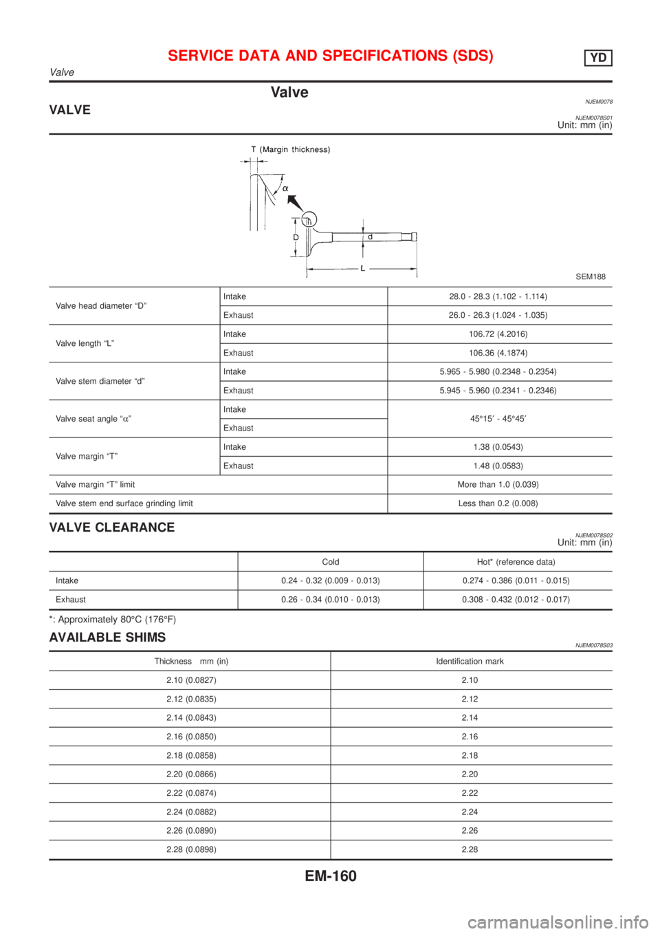
ValveNJEM0078VALVENJEM0078S01Unit: mm (in)
SEM188
Valve head diameter ªDºIntake 28.0 - 28.3 (1.102 - 1.114)
Exhaust 26.0 - 26.3 (1.024 - 1.035)
Valve length ªLºIntake 106.72 (4.2016)
Exhaust 106.36 (4.1874)
Valve stem diameter ªdºIntake 5.965 - 5.980 (0.2348 - 0.2354)
Exhaust 5.945 - 5.960 (0.2341 - 0.2346)
Valve seat angle ªaºIntake
45É15¢- 45É45¢
Exhaust
Valve margin ªTºIntake 1.38 (0.0543)
Exhaust 1.48 (0.0583)
Valve margin ªTº limitMore than 1.0 (0.039)
Valve stem end surface grinding limit Less than 0.2 (0.008)
VALVE CLEARANCENJEM0078S02Unit: mm (in)
Cold Hot* (reference data)
Intake 0.24 - 0.32 (0.009 - 0.013) 0.274 - 0.386 (0.011 - 0.015)
Exhaust 0.26 - 0.34 (0.010 - 0.013) 0.308 - 0.432 (0.012 - 0.017)
*: Approximately 80ÉC (176ÉF)
AVAILABLE SHIMSNJEM0078S03
Thickness mm (in) Identification mark
2.10 (0.0827) 2.10
2.12 (0.0835) 2.12
2.14 (0.0843) 2.14
2.16 (0.0850) 2.16
2.18 (0.0858) 2.18
2.20 (0.0866) 2.20
2.22 (0.0874) 2.22
2.24 (0.0882) 2.24
2.26 (0.0890) 2.26
2.28 (0.0898) 2.28
SERVICE DATA AND SPECIFICATIONS (SDS)YD
Valve
EM-160
Page 240 of 2493
VALVE LIFTERNJEM0078S05Unit: mm (in)
Valve lifter outer diameter 29.960 - 29.975 (1.1795 - 1.1801)
Lifter guide inner diameter 30.000 - 30.021 (1.1181 - 1.1819)
Clearance between lifter and lifter guide 0.025 - 0.061 (0.0010 - 0.0024)
VALVE GUIDENJEM0078S06Unit: mm (in)
JEM156G
Standard Service
Valve guide Outer diameter 10.023 - 10.034 (0.3946 - 0.3950) 10.223 - 10.234 (0.4025 - 0.4029)
Valve guide Inner diameter (Finished size) 6.000 - 6.018 (0.2362 - 0.2369)
Cylinder head valve guide hole diameter 9.975 - 9.996 (0.3927 - 0.3935) 10.175 - 10.196 (0.4006 - 0.4014)
Interference fit of valve guide 0.027 - 0.059 (0.0011 - 0.0023)
Standard Limit
Stem to guide clearanceIntake 0.020 - 0.053 (0.0008 - 0.0021) 0.08 (0.0031)
Exhaust 0.040 - 0.073 (0.0016 - 0.0029) 0.1 (0.004)
Valve deflection limit0.15 (0.0059)
Projection length10.4 - 10.6 (0.4094 - 0.4173)
SERVICE DATA AND SPECIFICATIONS (SDS)YD
Valve (Cont'd)
EM-162
Page 241 of 2493
Valve SeatNJEM0079Unit: mm (in)
SEM546G
JEM253G
Standard Service
Cylinder head seat recess diameter (D)Intake 30.000 - 30.016 (1.1181 - 1.1817) 30.500 - 30.516 (1.2008 - 1.2014)
Exhaust 29.000 - 29.016 (1.1417 - 1.1424) 29.500 - 29.516 (1.1614 - 1.1620)
Valve seat interference fitIntake 0.064 - 0.100 (0.0025 - 0.0039)
Exhaust 0.064 - 0.096 (0.0025 - 0.0038)
Valve seat outer diameter (d)Intake 30.080 - 30.100 (1.1842 - 1.1850) 30.580 - 30.600 (1.2039 - 1.2047)
Exhaust 29.080 - 29.096 (1.1449 - 1.1455) 29.580 - 29.596 (1.1646 - 1.1652)
SERVICE DATA AND SPECIFICATIONS (SDS)YD
Valve Seat
EM-163
Page 243 of 2493
Camshaft and Camshaft Bearing=NJEM0080Unit: mm (in)
Standard Limit
Camshaft journal to bearing clearance 0.045 - 0.086 (0.0018 - 0.0034) 0.045 - 0.086 (0.0018 - 0.0034)
Inner diameter of camshaft bearingNo. 1
30.500 - 30.521 (1.2008 - 1.2016)
No. 2, 3, 4, 5
24.000 - 24.021 (0.9449 - 0.9457)Ð
Outer diameter of camshaft journalNo. 1
30.435 - 30.455 (1.1982 - 1.1990)
No. 2, 3, 4, 5
23.935 - 23.955 (0.9423 - 0.9431)Ð
Camshaft runout [TIR*] Ð 0.02 (0.0008)
Camshaft sprocket runout [TIR*] Less than 0.15 (0.0059) Ð
Camshaft end play 0.070 - 0.148 (0.0028 - 0.0058) 0.24 (0.0094)
*: Total indicator reading
EM671
Cam height ªAºIntake 39.505 - 39.695 (1.5553 - 1.5628)
Exhaust 39.905 - 40.095 (1.5711 - 1.5785)
Wear limit of cam height0.15 (0.0059)
Valve timing
EM120
Unit: degree
abcde f
Valve timing 224 212 2 30 ±2 46
SERVICE DATA AND SPECIFICATIONS (SDS)YD
Camshaft and Camshaft Bearing
EM-165
Page 244 of 2493
Cylinder BlockNJEM0081Unit: mm (in)
JEM207G
Surface flatnessStandardLess than 0.03 (0.0012)
Limit0.04 (0.0016)
Cylinder bore Inner diameterStandardGrade No. 1 86.000 - 86.010 (3.3858 - 3.3862)
Grade No. 2 86.010 - 86.020 (3.3862 - 3.3866)
Grade No. 3 86.020 - 86.030 (3.3866 - 3.3870)
Wear limit 0.07 (0.0028)
Out-of-round (X þ Y)Less than 0.015 (0.0006)
Taper (AþBþC)Less than 0.010 (0.0004)
Main journal inner
diameter grade
(Without bearing)Grade No. 0
Grade No. 1
Grade No. 266.654 - 66.663 (2.6242 - 2.6245)
66.663 - 66.672 (2.6245 - 2.6249)
66.672 - 66.681 (2.6249 - 2.6252)
Difference in inner
diameter between
cylindersLimitLess than 0.05 (0.0020)
SERVICE DATA AND SPECIFICATIONS (SDS)YD
Cylinder Block
EM-166