2001 NISSAN ALMERA N16 overheating
[x] Cancel search: overheatingPage 249 of 2493

ENGINE LUBRICATION &
COOLING SYSTEMS
SECTION
LC
CONTENTS
QG
ENGINE LUBRICATION SYSTEM..................................3
Precautions ..................................................................3
LIQUID GASKET APPLICATION PROCEDURE............3
Preparation ..................................................................3
SPECIAL SERVICE TOOLS........................................3
Lubrication Circuit ........................................................4
Oil Pressure Check......................................................5
Oil Pump ......................................................................5
REMOVAL AND INSTALLATION.................................5
DISASSEMBLY AND ASSEMBLY................................6
INSPECTION.............................................................7
REGULATOR VALVE INSPECTION............................7
Changing Engine Oil....................................................8
Changing Oil Filter .......................................................9
Service Data and Specifications (SDS).....................10
OIL PRESSURE CHECK..........................................10
OIL PUMP INSPECTION..........................................10
REGULATOR VALVE INSPECTION..........................10
OIL CAPACITY........................................................10
ENGINE COOLING SYSTEM........................................ 11
Precautions ................................................................ 11
LIQUID GASKET APPLICATION PROCEDURE.......... 11
Preparation ................................................................ 11
SPECIAL SERVICE TOOLS...................................... 11
Cooling Circuit ...........................................................12
System Check............................................................12
CHECKING COOLING SYSTEM HOSES...................12
CHECKING RADIATOR............................................13
CHECKING RADIATOR CAP....................................13
CHECKING COOLING SYSTEM FOR LEAKS............13
Water Pump ...............................................................14
REMOVAL AND INSTALLATION...............................14
INSPECTION...........................................................14
Thermostat .................................................................15
REMOVAL AND INSTALLATION...............................15
INSPECTION...........................................................16
Radiator .....................................................................16
COMPONENTS.......................................................16
Cooling Fan ...............................................................17
COMPONENTS.......................................................17
CONTROL SYSTEM................................................17
Changing Engine Coolant..........................................17
- DRAINING ENGINE COOLANT -............................17
- REFILLING ENGINE COOLANT -...........................18
- FLUSHING COOLING SYSTEM -............................19
Radiator (Aluminum type) ..........................................20
PREPARATION.......................................................20
DISASSEMBLY........................................................20
ASSEMBLY.............................................................21
INSPECTION...........................................................22
Overheating Cause Analysis .....................................23
Service Data and Specifications (SDS).....................24
THERMOSTAT........................................................24
RADIATOR..............................................................24
COOLANT CAPACITY..............................................24
YD
ENGINE LUBRICATION SYSTEM................................25
Precautions ................................................................25
LIQUID GASKET APPLICATION PROCEDURE..........25
Preparation ................................................................25
SPECIAL SERVICE TOOLS......................................25
Lubrication Circuit ......................................................26
Oil Pressure Check....................................................27
Oil Pump ....................................................................27
REMOVAL AND INSTALLATION...............................27
DISASSEMBLY AND ASSEMBLY..............................28
OIL PUMP INSPECTION..........................................28
REGULATOR VALVE INSPECTION..........................29
Changing Engine Oil..................................................30
Oil Filter Bracket ........................................................31
REMOVAL AND INSTALLATION...............................31
Changing Oil Filter .....................................................31
REMOVAL...............................................................32
INSTALLATION........................................................32
Oil Cooler ...................................................................33
REMOVAL AND INSTALLATION...............................33
Service Data and Specifications (SDS).....................34
OIL PRESSURE CHECK..........................................34
Page 250 of 2493

REGULATOR VALVE INSPECTION..........................34
OIL PUMP INSPECTION..........................................34
ENGINE OIL CAPACITY...........................................34
ENGINE COOLING SYSTEM........................................35
Precautions ................................................................35
LIQUID GASKET APPLICATION PROCEDURE..........35
Preparation ................................................................35
SPECIAL SERVICE TOOLS......................................35
Cooling Circuit ...........................................................36
System Check............................................................37
CHECKING COOLING SYSTEM HOSES...................37
CHECKING RADIATOR............................................37
CHECKING RADIATOR CAP....................................37
CHECKING COOLING SYSTEM FOR LEAKS............38
Water Pump ...............................................................38
REMOVAL AND INSTALLATION...............................38
REMOVAL...............................................................39
INSPECTION...........................................................39
INSTALLATION........................................................39
Thermostat .................................................................40
REMOVAL AND INSTALLATION...............................40
INSPECTION...........................................................41
Radiator .....................................................................41
COMPONENTS.......................................................41
REMOVAL AND INSTALLATION...............................42
Cooling Fan ...............................................................42
COMPONENTS.......................................................42
CONTROL SYSTEM................................................42
Changing Engine Coolant..........................................43
- DRAINING ENGINE COOLANT -............................43
- REFILLING ENGINE COOLANT -...........................43
- FLUSHING COOLING SYSTEM -............................45
Radiator (Aluminum type) ..........................................46
Overheating Cause Analysis .....................................46
Service Data and Specifications (SDS).....................47
THERMOSTAT........................................................47
RADIATOR..............................................................47
ENGINE COOLANT CAPACITY................................47
CONTENTS(Cont'd)
LC-2
Page 271 of 2493

SLC934
2. Check for leakage.
Overheating Cause AnalysisNJLC0028
Symptom Check items
Cooling sys-
tem parts
malfunctionPoor heat transferWater pump malfunction Worn or loose drive belt
Ð Thermostat stuck closed Ð
Damaged finsDust contamination or
paper clogging
Mechanical damage
Clogged radiator cooling
tubeExcess foreign material
(rust, dirt, sand, etc.)
Reduced air flowCooling fan does not oper-
ate
ÐÐ High resistance to fan rota-
tion
Damaged fan blades
Damaged radiator shroud Ð Ð Ð
Improper coolant mixture
ratioÐÐÐ
Poor coolant quality Ð Ð Ð
Insufficient coolantCoolant leaksCooling hoseLoose clamp
Cracked hose
Water pump Poor sealing
Radiator capLoose
Poor sealing
RadiatorO-ring for damage, deterio-
ration or improper fitting
Cracked radiator tank
Cracked radiator core
Reservoir tank Cracked reservoir tank
Overflowing reservoir tankExhaust gas leaks into
cooling systemCylinder head deterioration
Cylinder head gasket dete-
rioration
ENGINE COOLING SYSTEMQG
Radiator (Aluminum type) (Cont'd)
LC-23
Page 272 of 2493

Symptom Check items
Except cool-
ing system
parts mal-
functionÐ Overload on engineAbusive drivingHigh engine rpm under no
load
Driving in low gear for
extended time
Driving at extremely high
speed
Powertrain system malfunc-
tion
Ð Installed improper size
wheels and tires
Dragging brakes
Improper ignition timing
Blocked or restricted air
flowBlocked bumper Ð
Ð Blocked radiator grilleInstalled car brassiere
Mud contamination or
paper clogging
Blocked radiator Ð
Blocked condenser
Ð
Installed large fog lamp
Service Data and Specifications (SDS)
THERMOSTATNJLC0029
Valve opening temperature ÉC (ÉF) 82 (180)
Valve lift mm/ÉC (in/ÉF)More than 8/95 (0.31/203)
RADIATORNJLC0030Unit: kPa (bar, kg/cm2, psi)
Cap reliefpressureStandard 78 - 98 (0.78 - 0.98, 0.8 - 1.0, 11 - 14)
Limit 59 - 98 (0.59 - 0.98, 0.6 - 1.0,9-14)
Leakage test pressure157 (1.57, 1.6, 23)
COOLANT CAPACITYNJLC0038Unit:!(Imp qt)
M/T*6.7 (5-7/8)
A/T*Sedan 6.6 (5-7/8)
Hatchback 6.7 (5-7/8)
Reservoir tank0.7 (5/8)
*: With reservoir tank
ENGINE COOLING SYSTEMQG
Overheating Cause Analysis (Cont'd)
LC-24
Page 294 of 2493

Radiator (Aluminum type)=NJLC0082Refer to LC-20, ªRadiator (Aluminum type)º.
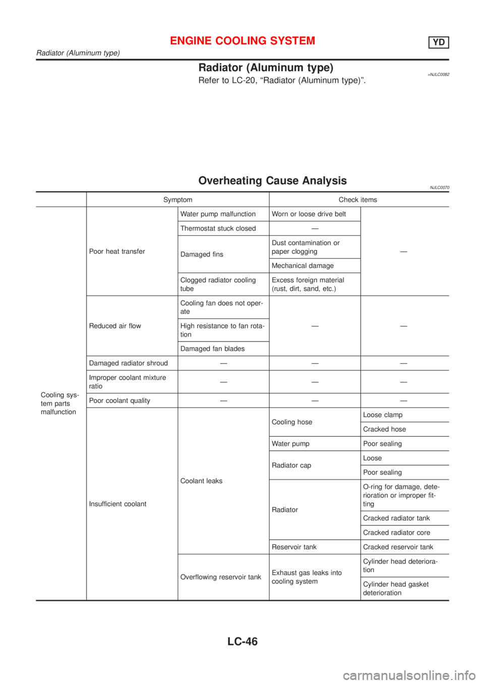
Overheating Cause AnalysisNJLC0070
Symptom Check items
Cooling sys-
tem parts
malfunctionPoor heat transferWater pump malfunction Worn or loose drive belt
Ð Thermostat stuck closed Ð
Damaged finsDust contamination or
paper clogging
Mechanical damage
Clogged radiator cooling
tubeExcess foreign material
(rust, dirt, sand, etc.)
Reduced air flowCooling fan does not oper-
ate
ÐÐ High resistance to fan rota-
tion
Damaged fan blades
Damaged radiator shroud Ð Ð Ð
Improper coolant mixture
ratioÐÐÐ
Poor coolant quality Ð Ð Ð
Insufficient coolantCoolant leaksCooling hoseLoose clamp
Cracked hose
Water pump Poor sealing
Radiator capLoose
Poor sealing
RadiatorO-ring for damage, dete-
rioration or improper fit-
ting
Cracked radiator tank
Cracked radiator core
Reservoir tank Cracked reservoir tank
Overflowing reservoir tankExhaust gas leaks into
cooling systemCylinder head deteriora-
tion
Cylinder head gasket
deterioration
ENGINE COOLING SYSTEMYD
Radiator (Aluminum type)
LC-46
Page 295 of 2493

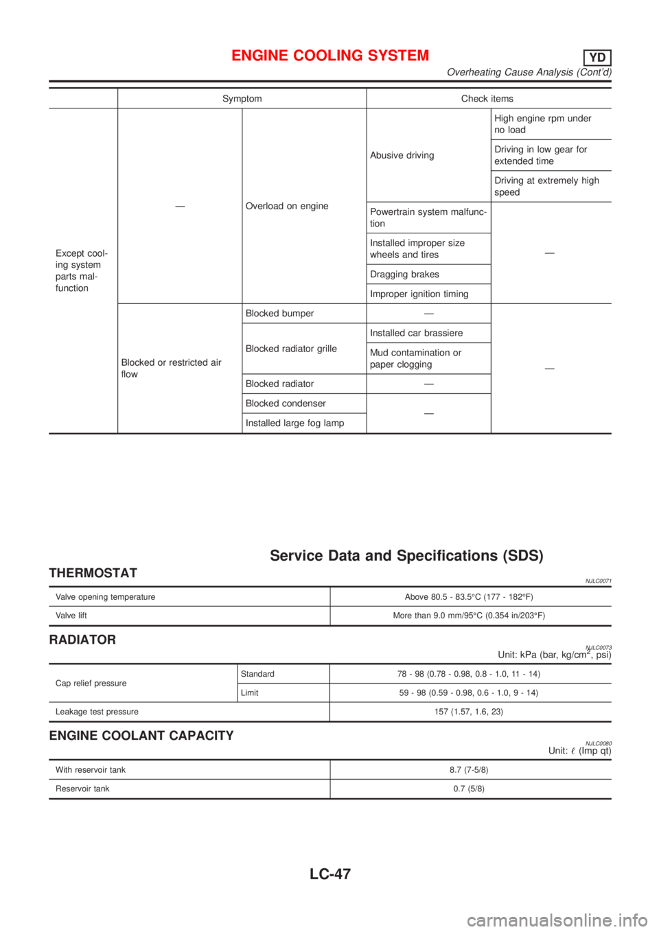
Symptom Check items
Except cool-
ing system
parts mal-
functionÐ Overload on engineAbusive drivingHigh engine rpm under
no load
Driving in low gear for
extended time
Driving at extremely high
speed
Powertrain system malfunc-
tion
Ð Installed improper size
wheels and tires
Dragging brakes
Improper ignition timing
Blocked or restricted air
flowBlocked bumper Ð
Ð Blocked radiator grilleInstalled car brassiere
Mud contamination or
paper clogging
Blocked radiator Ð
Blocked condenser
Ð
Installed large fog lamp
Service Data and Specifications (SDS)
THERMOSTATNJLC0071
Valve opening temperature Above 80.5 - 83.5ÉC (177 - 182ÉF)
Valve liftMore than 9.0 mm/95ÉC (0.354 in/203ÉF)
RADIATORNJLC0073Unit: kPa (bar, kg/cm2, psi)
Cap relief pressureStandard 78 - 98 (0.78 - 0.98, 0.8 - 1.0, 11 - 14)
Limit 59 - 98 (0.59 - 0.98, 0.6 - 1.0,9-14)
Leakage test pressure157 (1.57, 1.6, 23)
ENGINE COOLANT CAPACITYNJLC0080Unit:!(Imp qt)
With reservoir tank8.7 (7-5/8)
Reservoir tank0.7 (5/8)
ENGINE COOLING SYSTEMYD
Overheating Cause Analysis (Cont'd)
LC-47
Page 300 of 2493

Diagnostic Procedure ..............................................281
Component Inspection .............................................284
DTC P0400 EGR FUNCTION (CLOSED) (WHERE
FITTED)........................................................................285
Description ...............................................................285
CONSULT-II Reference Value in Data Monitor
Mode ........................................................................286
ECM Terminals and Reference Value .....................286
On Board Diagnosis Logic.......................................286
DTC Confirmation Procedure ..................................287
Wiring Diagram ........................................................289
Diagnostic Procedure ..............................................290
Component Inspection .............................................292
DTC P0403 EGR VOLUME CONTROL VALVE
(CIRCUIT).....................................................................293
Description ...............................................................293
CONSULT-II Reference Value in Data Monitor
Mode ........................................................................294
ECM Terminals and Reference Value .....................294
On Board Diagnosis Logic.......................................294
DTC Confirmation Procedure ..................................294
Wiring Diagram ........................................................296
Diagnostic Procedure ..............................................297
Component Inspection .............................................298
DTC P0420 THREE WAY CATALYST FUNCTION...299
On Board Diagnosis Logic.......................................299
DTC Confirmation Procedure ..................................299
Overall Function Check ...........................................300
Diagnostic Procedure ..............................................300
DTC P0443 EVAP CANISTER PURGE VOLUME
CONTROL SOLENOID VALVE (CIRCUIT).................304
Description ...............................................................304
CONSULT-II Reference Value in Data Monitor
Mode ........................................................................304
ECM Terminals and Reference Value .....................305
On Board Diagnosis Logic.......................................305
DTC Confirmation Procedure ..................................305
Wiring Diagram ........................................................306
Diagnostic Procedure ..............................................307
Component Inspection .............................................308
DTC P0500 VEHICLE SPEED SENSOR (VSS).........309
Component Description ...........................................309
ECM Terminals and Reference Value .....................309
On Board Diagnosis Logic.......................................309
DTC Confirmation Procedure ..................................309
Wiring Diagram ........................................................ 311
Diagnostic Procedure ..............................................312
DTC P0505 IDLE AIR CONTROL VALVE (IACV) -
AUXILIARY AIR CONTROL (AAC) VALVE...............313
Description ...............................................................313
CONSULT-II Reference Value in Data Monitor
Mode ........................................................................314ECM Terminals and Reference Value .....................314
On Board Diagnosis Logic.......................................314
DTC Confirmation Procedure ..................................314
Wiring Diagram ........................................................315
Diagnostic Procedure ..............................................316
Component Inspection .............................................320
DTC P0510 CLOSED THROTTLE POSITION
SWITCH (WHERE FITTED).........................................321
Component Description ...........................................321
CONSULT-II Reference Value in Data Monitor
Mode ........................................................................321
ECM Terminals and Reference Value .....................321
On Board Diagnosis Logic.......................................321
DTC Confirmation Procedure ..................................321
Overall Function Check ...........................................322
Wiring Diagram ........................................................323
Diagnostic Procedure ..............................................324
Component Inspection .............................................325
DTC P0605 ECM.........................................................327
Component Description ...........................................327
On Board Diagnosis Logic.......................................327
DTC Confirmation Procedure ..................................327
Diagnostic Procedure ..............................................328
D T C P 1111INTAKE VALVE TIMING CONTROL
SOLENOID VALVE......................................................329
Component Description ...........................................329
Operation .................................................................329
CONSULT-II Reference Value in Data Monitor
Mode ........................................................................329
ECM Terminals and Reference Value .....................329
On Board Diagnosis Logic.......................................329
DTC Confirmation Procedure ..................................330
Wiring Diagram ........................................................331
Diagnostic Procedure ..............................................332
Component Inspection .............................................333
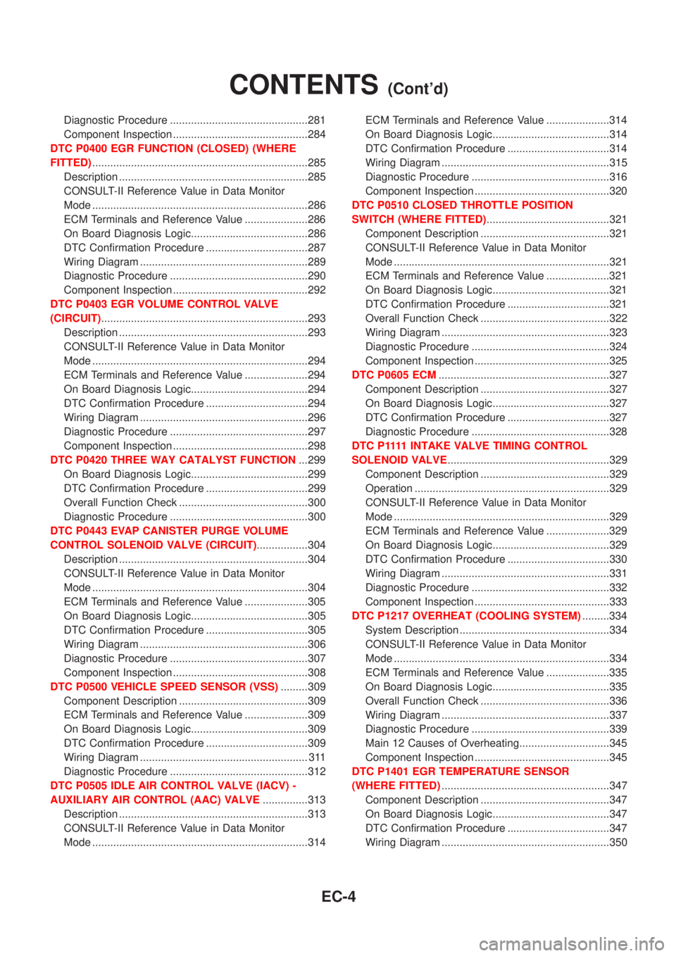
DTC P1217 OVERHEAT (COOLING SYSTEM).........334
System Description ..................................................334
CONSULT-II Reference Value in Data Monitor
Mode ........................................................................334
ECM Terminals and Reference Value .....................335
On Board Diagnosis Logic.......................................335
Overall Function Check ...........................................336
Wiring Diagram ........................................................337
Diagnostic Procedure ..............................................339
Main 12 Causes of Overheating..............................345
Component Inspection .............................................345
DTC P1401 EGR TEMPERATURE SENSOR
(WHERE FITTED)........................................................347
Component Description ...........................................347
On Board Diagnosis Logic.......................................347
DTC Confirmation Procedure ..................................347
Wiring Diagram ........................................................350
CONTENTS(Cont'd)
EC-4
Page 304 of 2493

DTC Confirmation Procedure ..................................604
Diagnostic Procedure ..............................................605
DTC P1180 P9.FUEL TEMP SEN...............................606
Description ...............................................................606
CONSULT-II Reference Value in Data Monitor
Mode ........................................................................606
ECM Terminals and Reference Value .....................607
On Board Diagnosis Logic.......................................607
DTC Confirmation Procedure ..................................607
Wiring Diagram ........................................................609
Diagnostic Procedure ..............................................610
DTC P1202 FUEL CUT SYSTEM2.............................612
Description ...............................................................612
CONSULT-II Reference Value in Data Monitor
Mode ........................................................................612
ECM Terminals and Reference Value .....................613
On Board Diagnosis Logic.......................................613
DTC Confirmation Procedure ..................................613
Wiring Diagram ........................................................615
Diagnostic Procedure ..............................................616
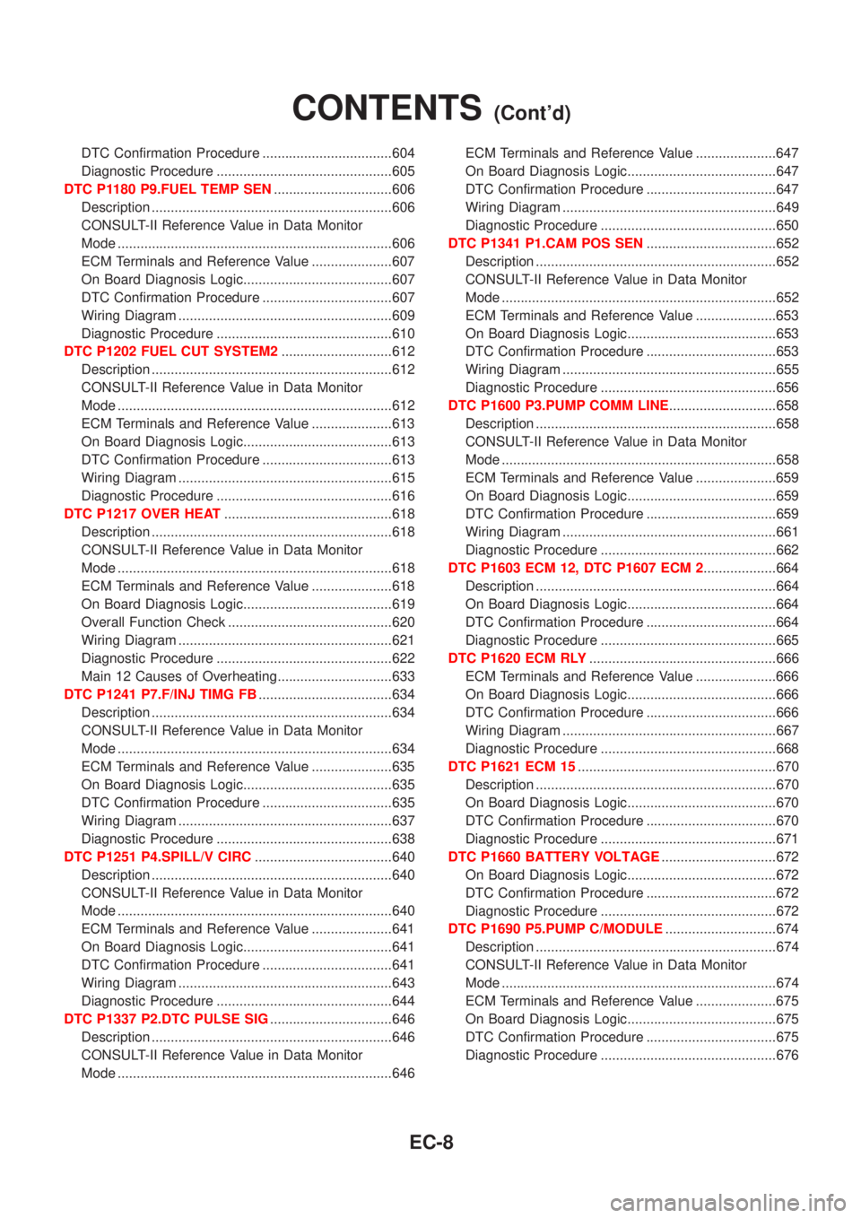
DTC P1217 OVER HEAT............................................618
Description ...............................................................618
CONSULT-II Reference Value in Data Monitor
Mode ........................................................................618
ECM Terminals and Reference Value .....................618
On Board Diagnosis Logic.......................................619
Overall Function Check ...........................................620
Wiring Diagram ........................................................621
Diagnostic Procedure ..............................................622
Main 12 Causes of Overheating..............................633
DTC P1241 P7.F/INJ TIMG FB...................................634
Description ...............................................................634
CONSULT-II Reference Value in Data Monitor
Mode ........................................................................634
ECM Terminals and Reference Value .....................635
On Board Diagnosis Logic.......................................635
DTC Confirmation Procedure ..................................635
Wiring Diagram ........................................................637
Diagnostic Procedure ..............................................638
DTC P1251 P4.SPILL/V CIRC....................................640
Description ...............................................................640
CONSULT-II Reference Value in Data Monitor
Mode ........................................................................640
ECM Terminals and Reference Value .....................641
On Board Diagnosis Logic.......................................641
DTC Confirmation Procedure ..................................641
Wiring Diagram ........................................................643
Diagnostic Procedure ..............................................644
DTC P1337 P2.DTC PULSE SIG................................646
Description ...............................................................646
CONSULT-II Reference Value in Data Monitor
Mode ........................................................................646ECM Terminals and Reference Value .....................647
On Board Diagnosis Logic.......................................647
DTC Confirmation Procedure ..................................647
Wiring Diagram ........................................................649
Diagnostic Procedure ..............................................650
DTC P1341 P1.CAM POS SEN..................................652
Description ...............................................................652
CONSULT-II Reference Value in Data Monitor
Mode ........................................................................652
ECM Terminals and Reference Value .....................653
On Board Diagnosis Logic.......................................653
DTC Confirmation Procedure ..................................653
Wiring Diagram ........................................................655
Diagnostic Procedure ..............................................656
DTC P1600 P3.PUMP COMM LINE............................658
Description ...............................................................658
CONSULT-II Reference Value in Data Monitor
Mode ........................................................................658
ECM Terminals and Reference Value .....................659
On Board Diagnosis Logic.......................................659
DTC Confirmation Procedure ..................................659
Wiring Diagram ........................................................661
Diagnostic Procedure ..............................................662
DTC P1603 ECM 12, DTC P1607 ECM 2...................664
Description ...............................................................664
On Board Diagnosis Logic.......................................664
DTC Confirmation Procedure ..................................664
Diagnostic Procedure ..............................................665
DTC P1620 ECM RLY.................................................666
ECM Terminals and Reference Value .....................666
On Board Diagnosis Logic.......................................666
DTC Confirmation Procedure ..................................666
Wiring Diagram ........................................................667
Diagnostic Procedure ..............................................668
DTC P1621 ECM 15....................................................670
Description ...............................................................670
On Board Diagnosis Logic.......................................670
DTC Confirmation Procedure ..................................670
Diagnostic Procedure ..............................................671
DTC P1660 BATTERY VOLTAGE..............................672
On Board Diagnosis Logic.......................................672
DTC Confirmation Procedure ..................................672
Diagnostic Procedure ..............................................672
DTC P1690 P5.PUMP C/MODULE.............................674
Description ...............................................................674
CONSULT-II Reference Value in Data Monitor
Mode ........................................................................674
ECM Terminals and Reference Value .....................675
On Board Diagnosis Logic.......................................675
DTC Confirmation Procedure ..................................675
Diagnostic Procedure ..............................................676
CONTENTS(Cont'd)
EC-8