Page 178 of 2493
JEM134G
9. Remove chain tensioner.
+When removing chain tensioner, push the sleeve of chain ten-
sioner and keep it pressed with a push pin, etc.
10. Remove timing chain slack guide.
JEM135G
11. Hold fuel injection pump sprocket and remove bolt.
a. Insert positioning stopper pin (SST) into the hole 6 mm (0.24
in) in the diameter on the fuel injection pump sprocket.
b. Using a TORX wrench (SST), turn pump shaft little by little to
adjust the position of fuel injection pump sprocket so that the
holes align.
c. Push positioning stopper pin (SST) through pump sprocket to
fuel injection pump body to hold pump sprocket, and remove
bolt.
JEM136G
12. Remove primary timing chain with fuel injection pump sprocket
and crankshaft sprocket.
JEM137G
13. Remove chain guide and tension guides.
14. Remove fuel injection pump.
15. Remove power steering pump.
TIMING CHAINYD
Primary Timing Chain (Cont'd)
EM-100
Page 181 of 2493
JEM137G
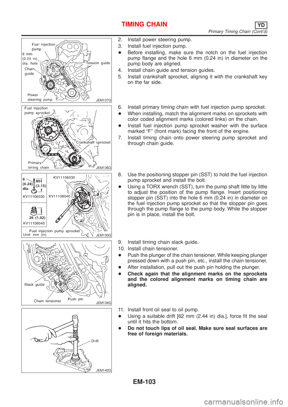
2. Install power steering pump.
3. Install fuel injection pump.
+Before installing, make sure the notch on the fuel injection
pump flange and the hole 6 mm (0.24 in) in diameter on the
pump body are aligned.
4. Install chain guide and tension guides.
5. Install crankshaft sprocket, aligning it with the crankshaft key
on the far side.
JEM136G
6. Install primary timing chain with fuel injection pump sprocket.
+When installing, match the alignment marks on sprockets with
color coded alignment marks (colored links) on the chain.
+Install fuel injection pump sprocket washer with the surface
marked ªFº (front mark) facing the front of the engine.
7. Install timing chain onto power steering pump sprocket and
through chain guide.
JEM135G
8. Use the positioning stopper pin (SST) to hold the fuel injection
pump sprocket and install the bolt.
+Using a TORX wrench (SST), turn the pump shaft little by little
to adjust the position of the pump flange. Insert positioning
stopper pin (SST) into the hole 6 mm (0.24 in) in diameter on
the fuel injection pump sprocket so that the stopper pin goes
through the pump flange to the pump body. While the stopper
pin is in place, install the bolt.
JEM134G
9. Install timing chain slack guide.
10. Install chain tensioner.
+Push the plunger of the chain tensioner. While keeping plunger
pressed down with a push pin, etc., install the chain tensioner.
+After installation, pull out the push pin holding the plunger.
+Check again that the alignment marks on the sprockets
and the colored alignment marks on timing chain are
aligned.
JEM142G
11. Install front oil seal to oil pump.
+Using a suitable drift [62 mm (2.44 in) dia.], force fit the seal
until it hits the bottom.
+Do not touch lips of oil seal. Make sure seal surfaces are
free of foreign materials.
TIMING CHAINYD
Primary Timing Chain (Cont'd)
EM-103
Page 200 of 2493
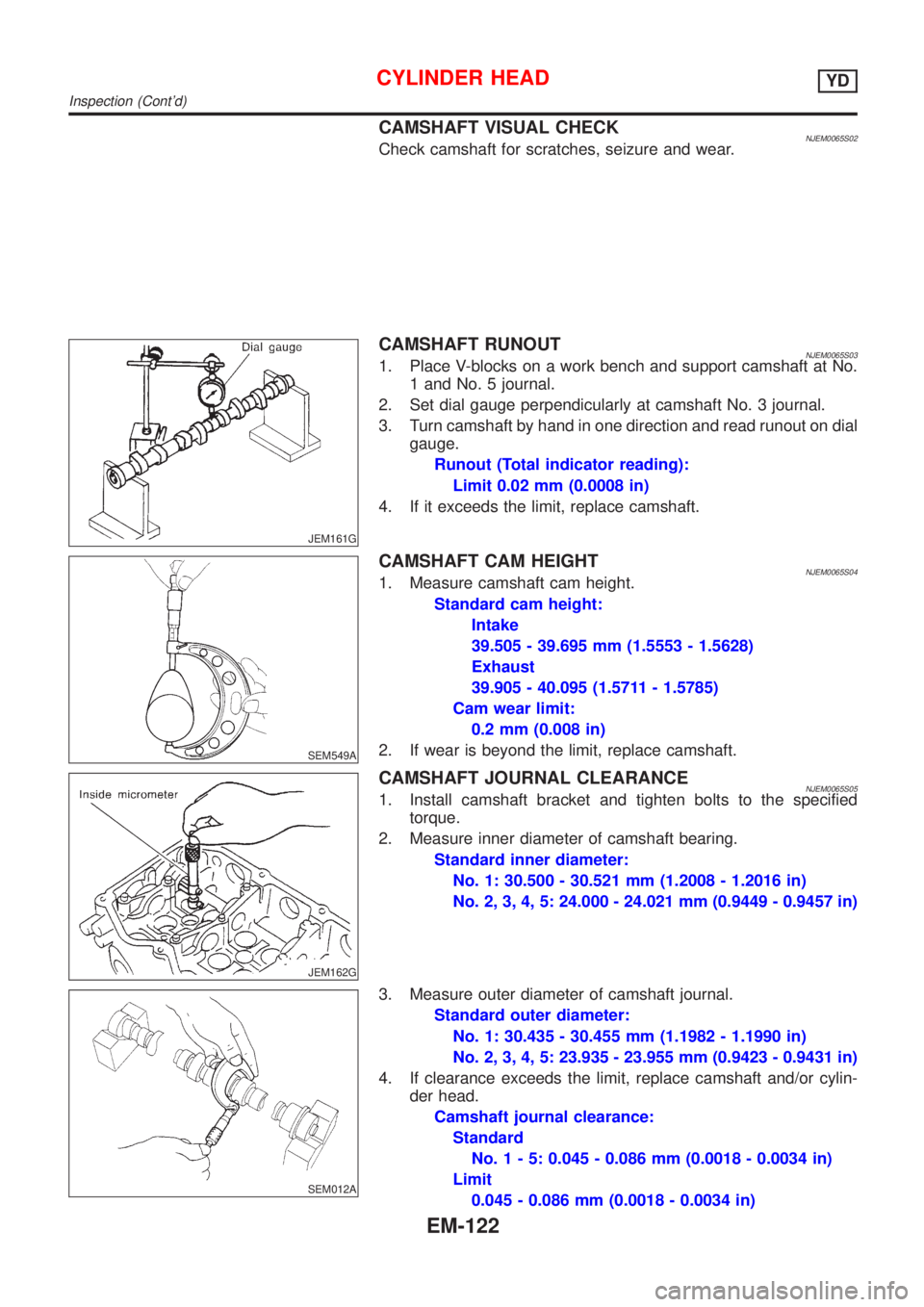
CAMSHAFT VISUAL CHECKNJEM0065S02Check camshaft for scratches, seizure and wear.
JEM161G
CAMSHAFT RUNOUTNJEM0065S031. Place V-blocks on a work bench and support camshaft at No.
1 and No. 5 journal.
2. Set dial gauge perpendicularly at camshaft No. 3 journal.
3. Turn camshaft by hand in one direction and read runout on dial
gauge.
Runout (Total indicator reading):
Limit 0.02 mm (0.0008 in)
4. If it exceeds the limit, replace camshaft.
SEM549A
CAMSHAFT CAM HEIGHTNJEM0065S041. Measure camshaft cam height.
Standard cam height:
Intake
39.505 - 39.695 mm (1.5553 - 1.5628)
Exhaust
39.905 - 40.095 (1.5711 - 1.5785)
Cam wear limit:
0.2 mm (0.008 in)
2. If wear is beyond the limit, replace camshaft.
JEM162G
CAMSHAFT JOURNAL CLEARANCENJEM0065S051. Install camshaft bracket and tighten bolts to the specified
torque.
2. Measure inner diameter of camshaft bearing.
Standard inner diameter:
No. 1: 30.500 - 30.521 mm (1.2008 - 1.2016 in)
No. 2, 3, 4, 5: 24.000 - 24.021 mm (0.9449 - 0.9457 in)
SEM012A
3. Measure outer diameter of camshaft journal.
Standard outer diameter:
No. 1: 30.435 - 30.455 mm (1.1982 - 1.1990 in)
No. 2, 3, 4, 5: 23.935 - 23.955 mm (0.9423 - 0.9431 in)
4. If clearance exceeds the limit, replace camshaft and/or cylin-
der head.
Camshaft journal clearance:
Standard
No.1-5:0.045 - 0.086 mm (0.0018 - 0.0034 in)
Limit
0.045 - 0.086 mm (0.0018 - 0.0034 in)
CYLINDER HEADYD
Inspection (Cont'd)
EM-122
Page 201 of 2493
JEM163G
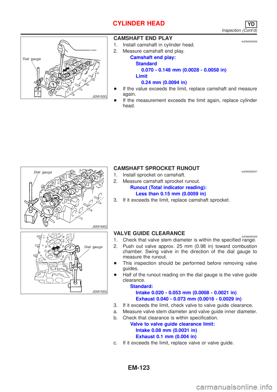
CAMSHAFT END PLAYNJEM0065S061. Install camshaft in cylinder head.
2. Measure camshaft end play.
Camshaft end play:
Standard
0.070 - 0.148 mm (0.0028 - 0.0058 in)
Limit
0.24 mm (0.0094 in)
+If the value exceeds the limit, replace camshaft and measure
again.
+If the measurement exceeds the limit again, replace cylinder
head.
JEM164G
CAMSHAFT SPROCKET RUNOUTNJEM0065S071. Install sprocket on camshaft.
2. Measure camshaft sprocket runout.
Runout (Total indicator reading):
Less than 0.15 mm (0.0059 in)
3. If it exceeds the limit, replace camshaft sprocket.
JEM155G
VALVE GUIDE CLEARANCENJEM0065S081. Check that valve stem diameter is within the specified range.
2. Push out valve approx. 25 mm (0.98 in) toward combustion
chamber. Swing valve in the direction of the dial gauge to
measure the runout.
+This inspection should be performed before removing valve
guides.
+Half of the runout reading on the dial gauge is the valve guide
clearance.
Standard:
Intake 0.020 - 0.053 mm (0.0008 - 0.0021 in)
Exhaust 0.040 - 0.073 mm (0.0016 - 0.0029 in)
3. If it exceeds the limit, check valve to valve guide clearance.
a. Measure valve stem diameter and valve guide inner diameter.
b. Check that clearance is within specification.
Valve to valve guide clearance limit:
Intake 0.08 mm (0.0031 in)
Exhaust 0.1 mm (0.004 in)
c. If it exceeds the limit, replace valve or valve guide.
CYLINDER HEADYD
Inspection (Cont'd)
EM-123
Page 202 of 2493
SEM008A
VALVE GUIDE REPLACEMENTNJEM0065S09+When a valve guide is removed, replace with an oversized [0.2
mm (0.008 in)] valve guide.
1. To remove valve guide, heat cylinder head to 110 to 130ÉC
(230 to 266ÉF) by soaking in heated oil.
SEM931C
2. Drive out valve guide with a press [under a 20 kN (2 ton, 2.2
US ton, 2.0 Imp ton) pressure] or hammer and suitable tool.
SEM932C
3. Ream cylinder head valve guide hole.
Valve guide hole diameter (for service parts):
10.175 - 10.196 mm (0.4006 - 0.4014 in)
JEM156G
4. Heat cylinder head to 110 to 130ÉC (230 to 266ÉF) and press
service valve guide onto cylinder head.
Projection ªLº:
10.4 - 10.6 mm (0.409 - 0.417 in)
5. Ream valve guide.
Finished size:
6.000 - 6.018 mm (0.2362 - 0.2369 in)
CYLINDER HEADYD
Inspection (Cont'd)
EM-124
Page 205 of 2493
SEM188A
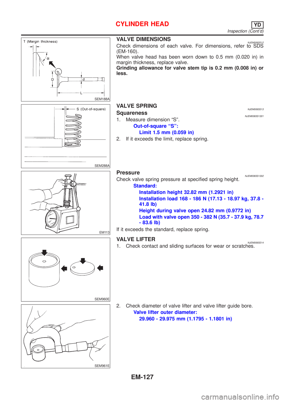
VALVE DIMENSIONSNJEM0065S12Check dimensions of each valve. For dimensions, refer to SDS
(EM-160).
When valve head has been worn down to 0.5 mm (0.020 in) in
margin thickness, replace valve.
Grinding allowance for valve stem tip is 0.2 mm (0.008 in) or
less.
SEM288A
VALVE SPRINGNJEM0065S13SquarenessNJEM0065S13011. Measure dimension ªSº.
Out-of-square ªSº:
Limit 1.5 mm (0.059 in)
2. If it exceeds the limit, replace spring.
EM113
PressureNJEM0065S1302Check valve spring pressure at specified spring height.
Standard:
Installation height 32.82 mm (1.2921 in)
Installation load 168 - 186 N (17.13 - 18.97 kg, 37.8 -
41.8 lb)
Height during valve open 24.82 mm (0.9772 in)
Load with valve open 350 - 382 N (35.7 - 37.9 kg, 78.7
- 83.6 lb)
If it exceeds the standard, replace spring.
SEM960E
VALVE LIFTERNJEM0065S141. Check contact and sliding surfaces for wear or scratches.
SEM961E
2. Check diameter of valve lifter and valve lifter guide bore.
Valve lifter outer diameter:
29.960 - 29.975 mm (1.1795 - 1.1801 in)
CYLINDER HEADYD
Inspection (Cont'd)
EM-127
Page 206 of 2493
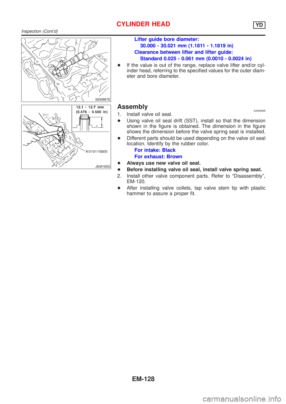
SEM867E
Lifter guide bore diameter:
30.000 - 30.021 mm (1.1811 - 1.1819 in)
Clearance between lifter and lifter guide:
Standard 0.025 - 0.061 mm (0.0010 - 0.0024 in)
+If the value is out of the range, replace valve lifter and/or cyl-
inder head, referring to the specified values for the outer diam-
eter and bore diameter.
JEM165G
AssemblyNJEM00661. Install valve oil seal.
+Using valve oil seal drift (SST), install so that the dimension
shown in the figure is obtained. The dimension in the figure
shows the dimension before the valve spring seat is installed.
+Different parts should be used depending on the valve oil seal
location. Identify by the rubber color.
For intake: Black
For exhaust: Brown
+Always use new valve oil seal.
+Before installing valve oil seal, install valve spring seat.
2. Install other valve component parts. Refer to ªDisassemblyº,
EM-120.
+After installing valve collets, tap valve stem tip with plastic
hammer to assure a proper fit.
CYLINDER HEADYD
Inspection (Cont'd)
EM-128
Page 208 of 2493
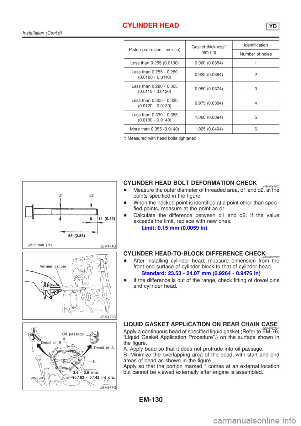
Piston protrusion mm (in)Gasket thickness*
mm (in)Identification
Number of holes
Less than 0.255 (0.0100) 0.900 (0.0354) 1
Less than 0.255 - 0.280
(0.0100 - 0.0110)0.925 (0.0364) 2
Less than 0.280 - 0.305
(0.0110 - 0.0120)0.950 (0.0374) 3
Less than 0.305 - 0.330
(0.0120 - 0.0130)0.975 (0.0384) 4
Less than 0.330 - 0.355
(0.0130 - 0.0140)1.000 (0.0394) 5
More than 0.355 (0.0140) 1.025 (0.0404) 6
*: Measured with head bolts tightened
JEM171G
CYLINDER HEAD BOLT DEFORMATION CHECKNJEM0067S02+Measure the outer diameter of threaded area, d1 and d2, at the
points specified in the figure.
+When the necked point is identified at a point other than speci-
fied points, measure at the point as d1.
+Calculate the difference between d1 and d2. If the value
exceeds the limit, replace with new ones.
Limit: 0.15 mm (0.0059 in)
JEM172G
CYLINDER HEAD-TO-BLOCK DIFFERENCE CHECKNJEM0067S03+After installing cylinder head, measure dimension from the
front end surface of cylinder block to that of cylinder head.
Standard: 23.53 - 24.07 mm (0.9264 - 0.9476 in)
+If the difference is out of the range, check fitting of dowel pins
and cylinder head.
JEM167G
LIQUID GASKET APPLICATION ON REAR CHAIN CASENJEM0067S04Apply a continuous bead of specified liquid gasket (Refer to EM-76,
ªLiquid Gasket Application Procedureº.) on the surface shown in
the figure.
A: Apply bead so that it does not protrude into oil passage.
B: Minimize the overlapping area of the bead, with start and end
areas of bead as shown in the figure.
Apply so that the portion marked * comes at an external location
but cannot be viewed externally after engine is assembled.
CYLINDER HEADYD
Installation (Cont'd)
EM-130