2001 NISSAN ALMERA N16 Meter
[x] Cancel search: MeterPage 70 of 2493

Maintenance Schedule for Petrol Engines
(Annual Mileage > 30,000 km/year)
=NJMA0043S04QG15DE/QG18DE ENGINESNJMA0043S0401Abbreviations: R = Replace I = Inspect: Correct or replace if necessary
MAINTENANCE OPERATIONMAINTENANCE INTERVAL
Refer-
ence
pages Perform on a kilometer basis only.km x 1,000
(miles x 1,000)15
(9)30
(18)45
(27)60
(36)75
(45)90
(54)105
(63)120
(72)
Engine compartment and under vehicle
Engine oil (Use recommended oil)HRRRRRRRRLC-8
Engine oil filter (Use NISSAN genuine
part or equivalent)HRRRRRRRRLC-9
Drive beltsIIIIIIIIEM-15
Cooling systemIIIILC-12
Engine anti-freeze coolant (Use genu-
ine NISSAN Anti-Freeze Coolant (L2N)
or equivalent)See NOTE (1) I R I LC-17
Air cleaner filterHR R EM-17
Intake & exhaust valve clearance See NOTE (2) EM-42
Fuel and EVAP vapor lines I IFE-5/
EC-36
Spark plugsRRRREM-18
Fuel filter See NOTE (3) FE-9
Heated oxygen sensorHSee NOTE (4)GI-40/
EC-45
NOTE:
(1) First replace at 90,000 km (54,000 miles), then every 60,000 km (36,000 miles). Perform ªIº (checking the mixture ratio and
correcting the mixture ratio if necessary) at the middle of replacement interval.
(2) Periodic maintenance is not required. However, if valve noise increases, check valve clearance.
(3) Fuel filter is maintenance-free. For service procedures, refer to FE section.
(4) Perform only according to ªMaintenance Under Severe Driving Conditionsº for models without Euro-OBD system. For
models with Euro-OBD system, periodic maintenance is not required.
HMaintenance items with ªHº should be performed more frequently according to ªMaintenance Under Severe Driving Con-
ditionsº.
PERIODIC MAINTENANCE (FOR EUROPE)
Maintenance Schedule for Petrol Engines (Annual Mileage > 30,000 km/year)
MA-14
Page 72 of 2493
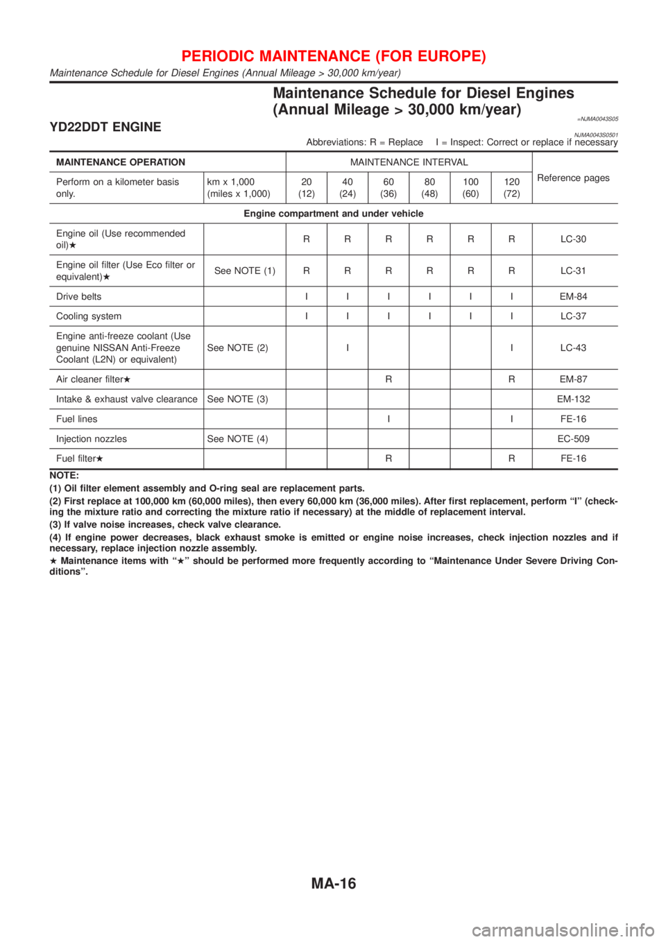
Maintenance Schedule for Diesel Engines
(Annual Mileage > 30,000 km/year)
=NJMA0043S05YD22DDT ENGINENJMA0043S0501Abbreviations: R = Replace I = Inspect: Correct or replace if necessary
MAINTENANCE OPERATIONMAINTENANCE INTERVAL
Reference pages
Perform on a kilometer basis
only.km x 1,000
(miles x 1,000)20
(12)40
(24)60
(36)80
(48)100
(60)120
(72)
Engine compartment and under vehicle
Engine oil (Use recommended
oil)HRRRRRRLC-30
Engine oil filter (Use Eco filter or
equivalent)HSee NOTE (1)RRRRRRLC-31
Drive beltsIIIIIIEM-84
Cooling systemIIIIIILC-37
Engine anti-freeze coolant (Use
genuine NISSAN Anti-Freeze
Coolant (L2N) or equivalent)See NOTE (2) I I LC-43
Air cleaner filterHR R EM-87
Intake & exhaust valve clearance See NOTE (3) EM-132
Fuel lines I I FE-16
Injection nozzles See NOTE (4) EC-509
Fuel filterHR R FE-16
NOTE:
(1) Oil filter element assembly and O-ring seal are replacement parts.
(2) First replace at 100,000 km (60,000 miles), then every 60,000 km (36,000 miles). After first replacement, perform ªIº (check-
ing the mixture ratio and correcting the mixture ratio if necessary) at the middle of replacement interval.
(3) If valve noise increases, check valve clearance.
(4) If engine power decreases, black exhaust smoke is emitted or engine noise increases, check injection nozzles and if
necessary, replace injection nozzle assembly.
HMaintenance items with ªHº should be performed more frequently according to ªMaintenance Under Severe Driving Con-
ditionsº.
PERIODIC MAINTENANCE (FOR EUROPE)
Maintenance Schedule for Diesel Engines (Annual Mileage > 30,000 km/year)
MA-16
Page 78 of 2493

SMA089D
Engine Coolant Mixture Ratio=NJMA0006S03The engine cooling system is filled at the factory with a high-quality,
year-round and extended life engine coolant. The high quality
engine coolant contains the specific solutions effective for the anti-
corrosion and the anti-freeze function. Therefore, additional cool-
ing system additives are not necessary.
CAUTION:
+For Europe
When adding or replacing coolant, be sure to use only
Genuine NISSAN Anti-freeze Coolant (L2N) or equivalent.
Because L2N is premixed type coolant.
+Except for Europe
When adding or replacing coolant, be sure to use only a
Nissan Genuine Engine Coolant or equivalent in its qual-
ity with the proper mixture ratio. See the examples shown
left.
The use of other types of engine coolant may damage your
cooling system.
+When checking the engine coolant mixture ratio by the coolant
hydrometer, use the chart below to correct your hydrometer
reading (specific gravity) according to coolant temperature.
Mixed coolant specific gravity
Unit: specific gravity
Engine coolant mixture
ratioCoolant temperature ÉC (ÉF)
15 (59) 25 (77) 35 (95) 45 (113)
30% 1.046 - 1.050 1.042 - 1.046 1.038 - 1.042 1.033 - 1.038
50% 1.076 - 1.080 1.070 - 1.076 1.065 - 1.071 1.059 - 1.065
WARNING:
Never remove the radiator cap when the engine is hot. Serious
burns could be caused by high pressure fluid escaping from
the radiator. Wait until the engine and radiator cool down.
RECOMMENDED FLUIDS AND LUBRICANTS
Engine Coolant Mixture Ratio
MA-22
Page 81 of 2493
CYLINDER HEAD DISTORTION.............................121
CAMSHAFT VISUAL CHECK..................................122
CAMSHAFT RUNOUT............................................122
CAMSHAFT CAM HEIGHT.....................................122
CAMSHAFT JOURNAL CLEARANCE......................122
CAMSHAFT END PLAY..........................................123
CAMSHAFT SPROCKET RUNOUT.........................123
VALVE GUIDE CLEARANCE..................................123
VALVE GUIDE REPLACEMENT..............................124
VALVE SEATS.......................................................125
REPLACING VALVE SEAT FOR SERVICE PARTS..125
VALVE DIMENSIONS.............................................127
VALVE SPRING.....................................................127
VALVE LIFTER......................................................127
Assembly .................................................................128
Installation ................................................................129
CYLINDER HEAD GASKET SELECTION.................129
CYLINDER HEAD BOLT DEFORMATION CHECK...130
CYLINDER HEAD-TO-BLOCK DIFFERENCE
CHECK
.................................................................130
LIQUID GASKET APPLICATION ON REAR CHAIN
CASE
....................................................................130
CYLINDER HEAD INSTALLATION..........................131
GLOW PLUG INSTALLATION.................................131
CAMSHAFT INSTALLATION...................................131
Valve Clearance.......................................................132
CHECKING...........................................................132
ADJUSTING..........................................................133
ENGINE ASSEMBLY...................................................136
Removal and Installation .........................................136
REMOVAL.............................................................137
INSTALLATION......................................................138
CYLINDER BLOCK.....................................................139
Components.............................................................139
Removal and Installation .........................................140
Disassembly.............................................................140
PISTON AND CRANKSHAFT..................................140
Inspection.................................................................143
CRANKSHAFT END PLAY.....................................143
CONNECTING ROD SIDE CLEARANCE.................143
PISTON AND PISTON PIN CLEARANCE................144
PISTON RING SIDE CLEARANCE..........................144
PISTON RING END GAP........................................145
CONNECTING ROD BEND AND TORSION.............145
CYLINDER BLOCK DISTORTION AND WEAR.........145
PISTON-TO-BORE CLEARANCE............................146
CRANKSHAFT.......................................................148
MAIN BEARING HOUSING INNER DIAMETER........148
BEARING CLEARANCE.........................................148
MAIN BEARING CRUSH HEIGHT...........................152
MAIN BEARING CAP BOLT DEFORMATION...........152
CONNECTING ROD BUSHING CLEARANCE
(SMALL END)
........................................................152
CONNECTING ROD BOLT DEFORMATION............153
FLYWHEEL RUNOUT............................................153
OIL JET................................................................153
OIL JET RELIEF VALVE.........................................154
Assembly .................................................................154
PISTON................................................................154
CRANKSHAFT.......................................................154
REPLACEMENT OF PILOT BUSHING.....................157
SERVICE DATA AND SPECIFICATIONS (SDS).......159
General Specifications .............................................159
Compression Pressure ............................................159
Belt Deflection..........................................................159
Cylinder Head ..........................................................159
Valve ........................................................................160
VALVE..................................................................160
VALVE CLEARANCE..............................................160
AVAILABLE SHIMS................................................160
VALVE SPRING.....................................................161
VALVE LIFTER......................................................162
VALVE GUIDE.......................................................162
Valve Seat................................................................163
Camshaft and Camshaft Bearing ............................165
Cylinder Block ..........................................................166
Piston, Piston Ring and Piston Pin .........................167
AVAILABLE PISTON..............................................167
PISTON RING.......................................................167
PISTON PIN..........................................................167
Connecting Rod .......................................................168
Crankshaft................................................................168
Available Main Bearing ............................................169
UNDERSIZE..........................................................169
Available Connecting Rod Bearing..........................169
CONNECTING ROD BEARING...............................169
UNDERSIZE..........................................................169
Miscellaneous Components.....................................169
BEARING CLEARANCE.........................................170
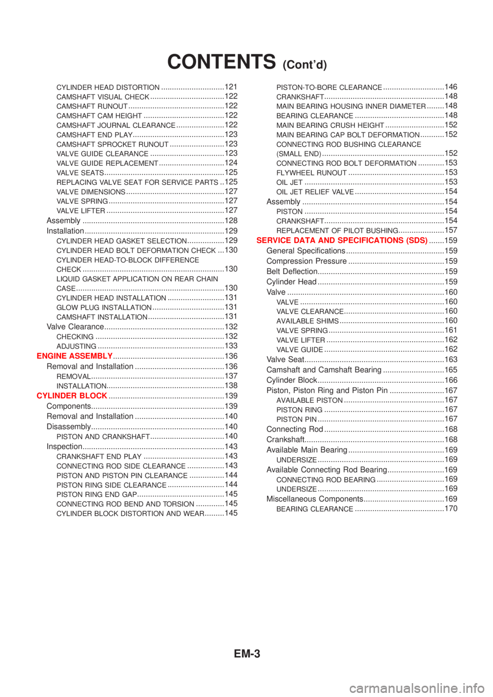
CONTENTS(Cont'd)
EM-3
Page 82 of 2493
Parts Requiring Angular TighteningNJEM0001+Use an angle wrench for the final tightening of the following
engine parts:
a) Cylinder head bolts
b) Main bearing cap bolts
c) Connecting rod cap nuts
+Do not use a torque value for final tightening.
+The torque value for these parts are for a preliminary step.
+Ensure thread and seat surfaces are clean and coated with
engine oil.
SEM164F
AEM080
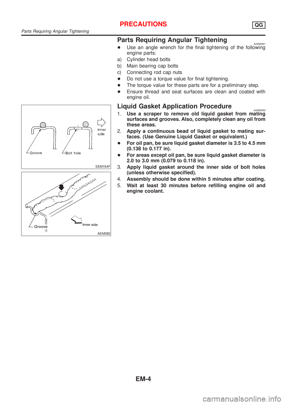
Liquid Gasket Application ProcedureNJEM00021.Use a scraper to remove old liquid gasket from mating
surfaces and grooves. Also, completely clean any oil from
these areas.
2.Apply a continuous bead of liquid gasket to mating sur-
faces. (Use Genuine Liquid Gasket or equivalent.)
+For oil pan, be sure liquid gasket diameter is 3.5 to 4.5 mm
(0.138 to 0.177 in).
+For areas except oil pan, be sure liquid gasket diameter is
2.0 to 3.0 mm (0.079 to 0.118 in).
3.Apply liquid gasket around the inner side of bolt holes
(unless otherwise specified).
4.Assembly should be done within 5 minutes after coating.
5.Wait at least 30 minutes before refilling engine oil and
engine coolant.
PRECAUTIONSQG
Parts Requiring Angular Tightening
EM-4
Page 99 of 2493
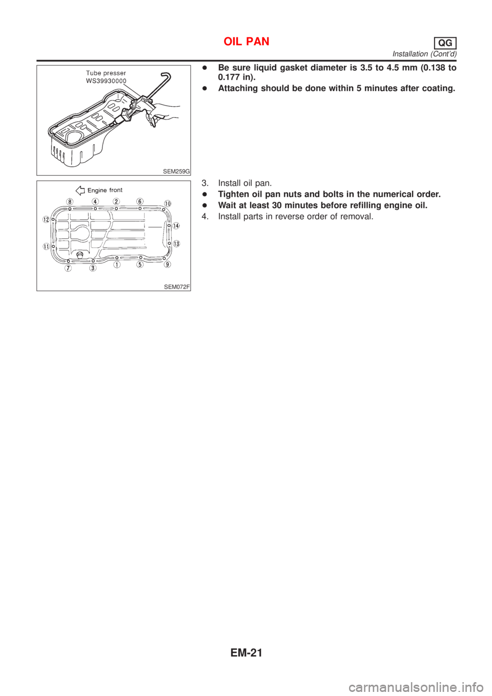
SEM259G
+Be sure liquid gasket diameter is 3.5 to 4.5 mm (0.138 to
0.177 in).
+Attaching should be done within 5 minutes after coating.
SEM072F
3. Install oil pan.
+Tighten oil pan nuts and bolts in the numerical order.
+Wait at least 30 minutes before refilling engine oil.
4. Install parts in reverse order of removal.
OIL PANQG
Installation (Cont'd)
EM-21
Page 115 of 2493
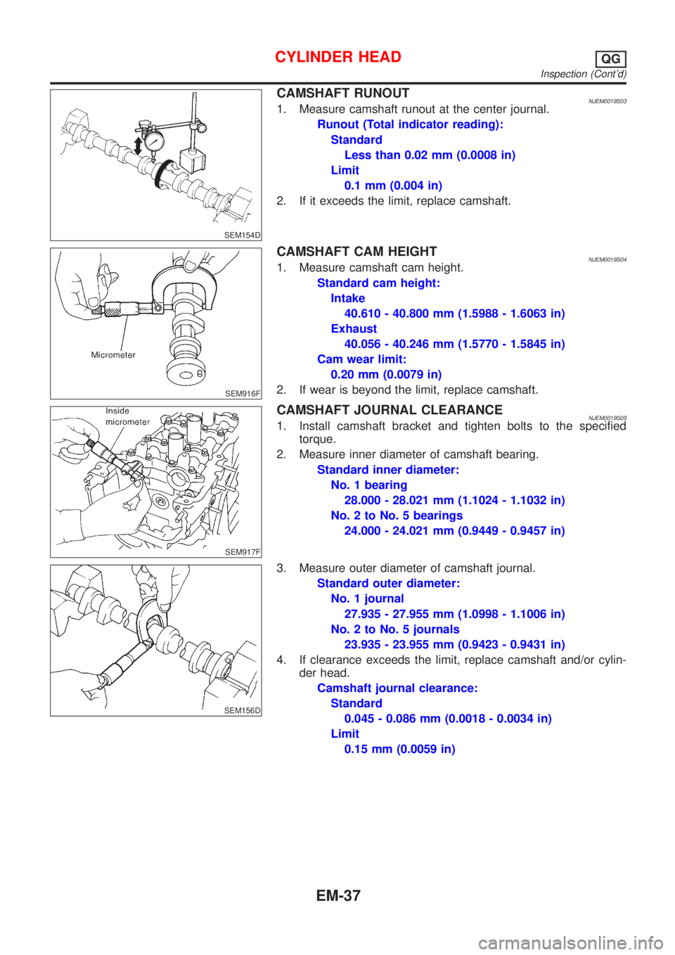
SEM154D
CAMSHAFT RUNOUTNJEM0019S031. Measure camshaft runout at the center journal.
Runout (Total indicator reading):
Standard
Less than 0.02 mm (0.0008 in)
Limit
0.1 mm (0.004 in)
2. If it exceeds the limit, replace camshaft.
SEM916F
CAMSHAFT CAM HEIGHTNJEM0019S041. Measure camshaft cam height.
Standard cam height:
Intake
40.610 - 40.800 mm (1.5988 - 1.6063 in)
Exhaust
40.056 - 40.246 mm (1.5770 - 1.5845 in)
Cam wear limit:
0.20 mm (0.0079 in)
2. If wear is beyond the limit, replace camshaft.
SEM917F
CAMSHAFT JOURNAL CLEARANCENJEM0019S051. Install camshaft bracket and tighten bolts to the specified
torque.
2. Measure inner diameter of camshaft bearing.
Standard inner diameter:
No. 1 bearing
28.000 - 28.021 mm (1.1024 - 1.1032 in)
No. 2 to No. 5 bearings
24.000 - 24.021 mm (0.9449 - 0.9457 in)
SEM156D
3. Measure outer diameter of camshaft journal.
Standard outer diameter:
No. 1 journal
27.935 - 27.955 mm (1.0998 - 1.1006 in)
No. 2 to No. 5 journals
23.935 - 23.955 mm (0.9423 - 0.9431 in)
4. If clearance exceeds the limit, replace camshaft and/or cylin-
der head.
Camshaft journal clearance:
Standard
0.045 - 0.086 mm (0.0018 - 0.0034 in)
Limit
0.15 mm (0.0059 in)
CYLINDER HEADQG
Inspection (Cont'd)
EM-37
Page 116 of 2493

SEM918F
CAMSHAFT END PLAYNJEM0019S061. Install camshaft in cylinder head. Refer to EM-45.
2. Measure camshaft end play.
Camshaft end play:
Standard
0.115 - 0.188 mm (0.0045 - 0.0074 in)
Limit
0.20 mm (0.0079 in)
3. If limit is exceeded, replace camshaft and remeasure end play.
+If limit is still exceeded after replacing camshaft, replace
cylinder head.
SEM919F
CAMSHAFT SPROCKET RUNOUTNJEM0019S071. Install sprocket on camshaft.
2. Measure camshaft sprocket runout.
Runout (Total indicator reading):
Limit 0.15 mm (0.0059 in)
3. If it exceeds the limit, replace camshaft sprocket.
SEM345D
VALVE GUIDE CLEARANCENJEM0019S081. Measure valve deflection as shown in figure. (Valve and valve
guide wear the most in this direction.)
Valve deflection limit (Dial gauge reading):
Intake & Exhaust
0.2 mm (0.008 in)
SEM938C
2. If it exceeds the limit, check valve to valve guide clearance.
a. Measure valve stem diameter and valve guide inner diameter.
b. Calculate valve to valve guide clearance.
Valve to valve guide clearance = valve guide inner diam-
eter þ valve stem diameter.
c. Check that clearance is within specification.
CYLINDER HEADQG
Inspection (Cont'd)
EM-38