2001 NISSAN ALMERA N16 shock
[x] Cancel search: shockPage 160 of 2493
NJEM0053
JEM111G
1. Warm up engine.
2. Turn ignition switch OFF.
3. Using CONSULT-II, make sure no error codes are indicated for
self-diagnosis items. Refer to EC-492, ªTrouble Diagnosis Ð
INDEXº.
+Do not disconnect CONSULT-II until the end of this operation;
it will be used to check engine rpm and for error detection at
the end of this operation.
4. Disconnect the negative battery terminal.
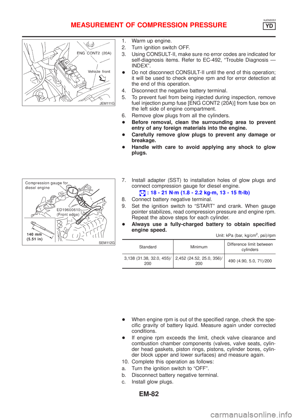
5. To prevent fuel from being injected during inspection, remove
fuel injection pump fuse [ENG CONT2 (20A)] from fuse box on
the left side of engine compartment.
6. Remove glow plugs from all the cylinders.
+Before removal, clean the surrounding area to prevent
entry of any foreign materials into the engine.
+Carefully remove glow plugs to prevent any damage or
breakage.
+Handle with care to avoid applying any shock to glow
plugs.
SEM112G
7. Install adapter (SST) to installation holes of glow plugs and
connect compression gauge for diesel engine.
: 18 - 21 N´m (1.8 - 2.2 kg-m, 13 - 15 ft-lb)
8. Connect battery negative terminal.
9. Set the ignition switch to ªSTARTº and crank. When gauge
pointer stabilizes, read compression pressure and engine rpm.
Repeat the above steps for each cylinder.
+Always use a fully-charged battery to obtain specified
engine speed.
Unit: kPa (bar, kg/cm2, psi)/rpm
Standard MinimumDifference limit between
cylinders
3,138 (31.38, 32.0, 455)/
2002,452 (24.52, 25.0, 356)/
200490 (4.90, 5.0, 71)/200
+When engine rpm is out of the specified range, check the spe-
cific gravity of battery liquid. Measure again under corrected
conditions.
+If engine rpm exceeds the limit, check valve clearance and
combustion chamber components (valves, valve seats, cylin-
der head gaskets, piston rings, pistons, cylinder bores, cylin-
der block upper and lower surfaces) and measure again.
10. Complete this operation as follows:
a. Turn the ignition switch to ªOFFº.
b. Disconnect battery negative terminal.
c. Install glow plugs.
MEASUREMENT OF COMPRESSION PRESSUREYD
EM-82
Page 185 of 2493

JEM238G
FUEL PIPINGNJEM0109S02RemovalNJEM0109S0201+To prevent fuel from flowing out, plug the opening of the hose
with a blind plug after disconnection.
+Be careful not to spill fuel in the engine compartment.
InstallationNJEM0109S0202+After repairing, bleed air in pipes by shifting priming pump up
and down until the touch is heavy.
+For further air bleeding, idle at least 1 minute or more.
SEM489G
INTAKE MANIFOLDNJEM0109S03RemovalNJEM0109S0301+Loosen bolts and nuts in the reverse order of that shown in the
figure.
InstallationNJEM0109S0302+When stud bolts come off, install with the following torque:
: 10 - 11 N´m (1.0 - 1.2 kg-m, 87 - 104 in-lb)
+Tighten fixing bolts in the numerical order shown in the figure.
EGR VOLUME CONTROL VALVENJEM0109S04+Handle with care avoiding any shocks.
+Do not disassemble or adjust.
SEM490G
WATER HOSENJEM0109S05InstallationNJEM0109S0501+Install water hose by referring to identification marks; avoiding
twisting.
+When an insert stopper is not provided with the pipe, insert the
hose up to dimension A. When the pipe is shorter than dimen-
sion A, insert hose fully until it reaches the end.
Dimension A: 25 - 30 mm (0.984 - 1.181 in)
+When an insert stopper is provided on the pipe side, insert the
hose until it reaches the bulge.
+When marking is provided on the pipe, insert hose until it cov-
ers half of the marking.
INTAKE MANIFOLDYD
Removal and Installation (Cont'd)
EM-107
Page 199 of 2493

JEM152G
+For the locations and arrangement of intake and exhaust
valves, refer to the figure.
JEM153G
5. Remove valve oil seals.
+Use a valve oil seal puller (SST) for removal.
6. Remove valve spring seats.
7. When removing valve seats, check valve seat contact. Refer
to EM-125.
8. Before removing valve guides, check valve guide clearance.
Refer to EM-123, ªVALVE GUIDE CLEARANCEº.
9. Remove glow plugs.
+To avoid damage, glow plugs should be removed only
when required.
+Handle with care to avoid applying shock. (When dropped
from approx. 100 mm (3.94 in) or higher, always replace
with a new one.)
SEM496G
InspectionNJEM0065CYLINDER HEAD DISTORTIONNJEM0065S01Clean surface of cylinder head.
Use a reliable straightedge and feeler gauge to check the flatness
of cylinder head surface.
Check along six positions shown in the figure.
Head surface flatness: Limit 0.04 mm (0.0016 in)
If beyond the specified limit, resurface or replace it.
The limit for cylinder head resurfacing is determined by the
cylinder block resurfacing.
Resurfacing limit:
Amount of cylinder head resurfacing is ªAº.
Amount of cylinder block resurfacing is ªBº.
The maximum limit: A+ B = 0.07 mm (0.0028 in)
After resurfacing cylinder head, check that camshaft rotates freely
by hand. If resistance is felt, cylinder head must be replaced.
Nominal cylinder head height:
153.9 - 154.1 mm (6.059 - 6.067 in)
CYLINDER HEADYD
Disassembly (Cont'd)
EM-121
Page 209 of 2493
JEM149G
JEM166G
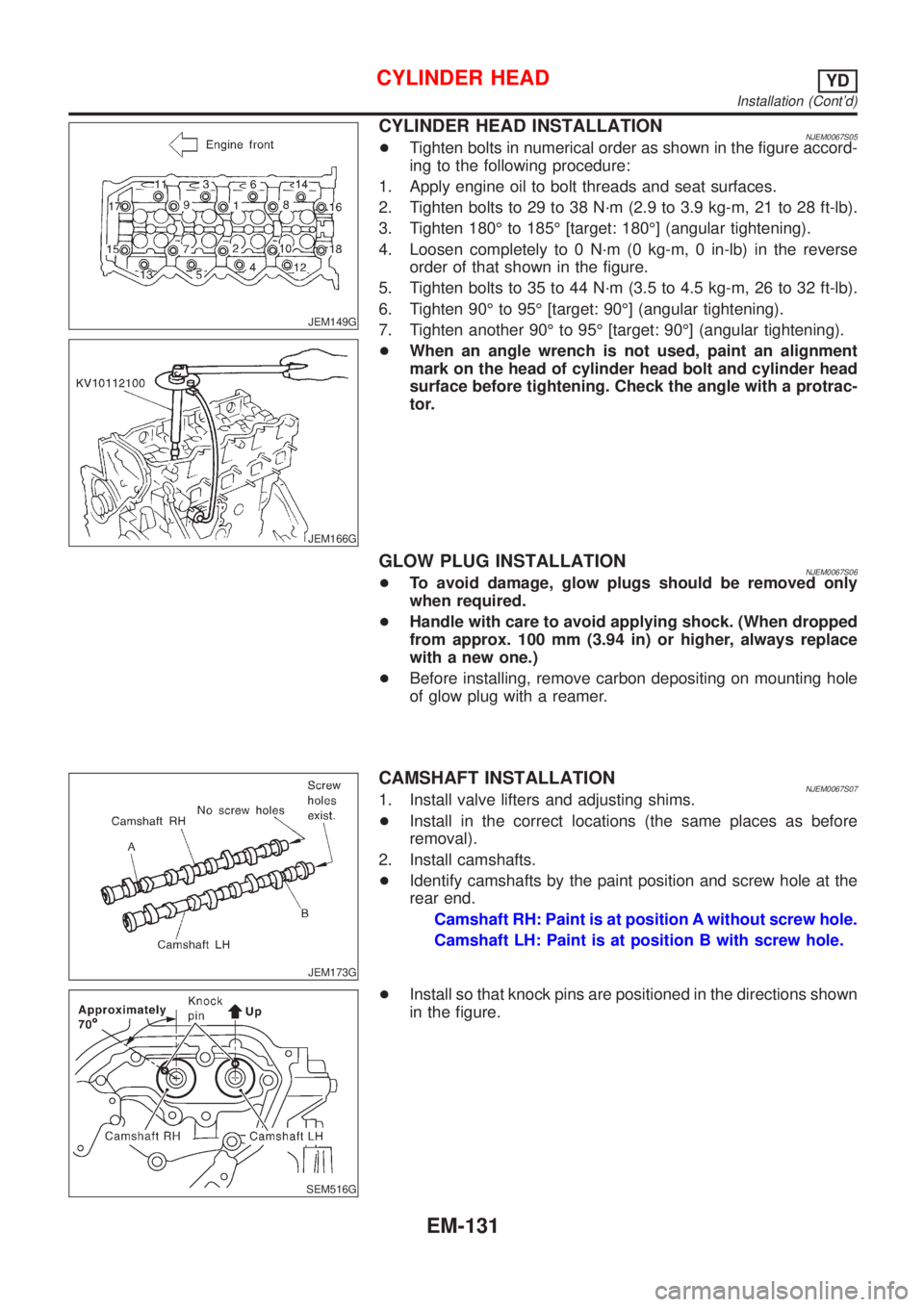
CYLINDER HEAD INSTALLATIONNJEM0067S05+Tighten bolts in numerical order as shown in the figure accord-
ing to the following procedure:
1. Apply engine oil to bolt threads and seat surfaces.
2. Tighten bolts to 29 to 38 N´m (2.9 to 3.9 kg-m, 21 to 28 ft-lb).
3. Tighten 180É to 185É [target: 180É] (angular tightening).
4. Loosen completely to 0 N´m (0 kg-m, 0 in-lb) in the reverse
order of that shown in the figure.
5. Tighten bolts to 35 to 44 N´m (3.5 to 4.5 kg-m, 26 to 32 ft-lb).
6. Tighten 90É to 95É [target: 90É] (angular tightening).
7. Tighten another 90É to 95É [target: 90É] (angular tightening).
+When an angle wrench is not used, paint an alignment
mark on the head of cylinder head bolt and cylinder head
surface before tightening. Check the angle with a protrac-
tor.
GLOW PLUG INSTALLATIONNJEM0067S06+To avoid damage, glow plugs should be removed only
when required.
+Handle with care to avoid applying shock. (When dropped
from approx. 100 mm (3.94 in) or higher, always replace
with a new one.)
+Before installing, remove carbon depositing on mounting hole
of glow plug with a reamer.
JEM173G
CAMSHAFT INSTALLATIONNJEM0067S071. Install valve lifters and adjusting shims.
+Install in the correct locations (the same places as before
removal).
2. Install camshafts.
+Identify camshafts by the paint position and screw hole at the
rear end.
Camshaft RH: Paint is at position A without screw hole.
Camshaft LH: Paint is at position B with screw hole.
SEM516G
+Install so that knock pins are positioned in the directions shown
in the figure.
CYLINDER HEADYD
Installation (Cont'd)
EM-131
Page 314 of 2493
MEF040D
+Handle mass air flow sensor carefully to avoid damage.
+Do not disassemble mass air flow sensor.
+Do not clean mass air flow sensor with any type of deter-
gent.
+Do not disassemble IAC valve-AAC valve.
+Even a slight leak in the air intake system can cause seri-
ous problems.
+Do not shock or jar the camshaft position sensor and
crankshaft position sensor.
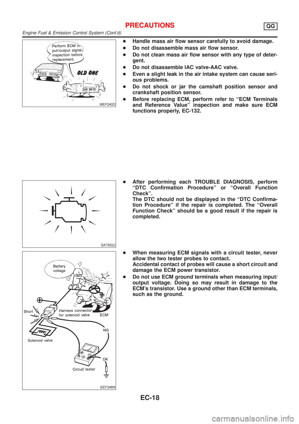
+Before replacing ECM, perform refer to ªECM Terminals
and Reference Valueº inspection and make sure ECM
functions properly, EC-132.
SAT652J
+After performing each TROUBLE DIAGNOSIS, perform
ªDTC Confirmation Procedureº or ªOverall Function
Checkº.
The DTC should not be displayed in the ªDTC Confirma-
tion Procedureº if the repair is completed. The ªOverall
Function Checkº should be a good result if the repair is
completed.
SEF348N
+When measuring ECM signals with a circuit tester, never
allow the two tester probes to contact.
Accidental contact of probes will cause a short circuit and
damage the ECM power transistor.
+Do not use ECM ground terminals when measuring input/
output voltage. Doing so may result in damage to the
ECM's transistor. Use a ground other than ECM terminals,
such as the ground.
PRECAUTIONSQG
Engine Fuel & Emission Control System (Cont'd)
EC-18
Page 1189 of 2493
Diagnostic Procedure ..............................................253
Component Inspection .............................................255
DTC P1705 THROTTLE POSITION SENSOR...........256
Description ...............................................................256
Wiring Diagram - AT - TPS ......................................259
Diagnostic Procedure ..............................................260
Component Inspection .............................................264
DTC P1760 OVERRUN CLUTCH SOLENOID
VALVE..........................................................................265
Description ...............................................................265
Wiring Diagram - AT - OVRCSV..............................267
Diagnostic Procedure ..............................................268
Component Inspection .............................................270
DTC BATT/FLUID TEMP SEN (A/T FLUID TEMP
SENSOR CIRCUIT AND TCM POWER SOURCE)....271
Description ...............................................................271
Wiring Diagram - AT - BA/FTS ................................273
Diagnostic Procedure ..............................................274
Component Inspection .............................................277
DTC VHCL SPEED SEN.MTR VEHICLE SPEED......278
Description ...............................................................278
Wiring Diagram - AT - VSSMTR ..............................280
Diagnostic Procedure ..............................................281
DTC CONTROL UNIT (RAM), CONTROL UNIT
(ROM)...........................................................................282
Description ...............................................................282
Diagnostic Procedure ..............................................282
DTC CONTROL UNIT (EEP ROM).............................284
Description ...............................................................284
Diagnostic Procedure ..............................................285
TROUBLE DIAGNOSES FOR SYMPTOMS...............286
Wiring Diagram - AT - NONDTC .............................286
1. O/D OFF Indicator Lamp Does Not Come On....288
2. Engine Cannot Be Started In²P²and²N²
Position ....................................................................291
3. In²P²Position, Vehicle Moves Forward Or
Backward When Pushed .........................................292
4. In²N²Position, Vehicle Moves ...........................293
5. Large Shock.²N²->²R²Position .......................295
6. Vehicle Does Not Creep Backward In²R²
Position ....................................................................297
7. Vehicle Does Not Creep Forward In²D²,²2²
Or²1²Position .........................................................300
8. Vehicle Cannot Be Started From D
1...................303
9. A/T Does Not Shift: D
1-> D2Or Does Not
Kickdown: D
4-> D2..................................................306
10. A/T Does Not Shift: D
2-> D3.............................309
11. A/T Does Not Shift: D
3-> D4.............................312
12. A/T Does Not Perform Lock-up .........................315
13. A/T Does Not Hold Lock-up Condition ..............31714. Lock-up Is Not Released ...................................319
15. Engine Speed Does Not Return To Idle (Light
Braking D
4-> D3).....................................................320
16. Vehicle Does Not Start From D
1.......................322
17. A/T Does Not Shift: D
4-> D3, When
Overdrive Control Switch²ON²->²OFF²...............323
18. A/T Does Not Shift: D
3-> 22, When Selector
Lever²D²->²2²Position.........................................324
19. A/T Does Not Shift: 2
2-> 11, When Selector
Lever²2²->²1²Position .........................................325
20. Vehicle Does Not Decelerate By Engine
Brake........................................................................326
21. TCM Self-diagnosis Does Not Activate (PNP,
Overdrive Control and Throttle Position Switches
Circuit Checks) ........................................................326
A/T SHIFT LOCK SYSTEM.........................................335
Description ...............................................................335
Shift Lock System Electrical Parts Location............335
Wiring Diagram - SHIFT -........................................336
Diagnostic Procedure ..............................................337
KEY INTERLOCK CABLE..........................................341
Components.............................................................341
Removal ...................................................................341
Installation ................................................................342
ON-VEHICLE SERVICE..............................................343
Control Valve Assembly and Accumulators .............343
Control Cable Adjustment ........................................344
Park/Neutral Position (PNP) Switch Adjustment .....344
Differential Side Oil Seal Replacement ...................345
Revolution Sensor Replacement .............................345
REMOVAL AND INSTALLATION...............................346
Removal ...................................................................346
Installation ................................................................347
OVERHAUL.................................................................349
Components-1 .........................................................349
Components-2 .........................................................350
Components-3 .........................................................351
Oil Channel ..............................................................352
Locations of Adjusting Shims, Needle Bearings,
Thrust Washers and Snap Rings ............................353
DISASSEMBLY............................................................354
REPAIR FOR COMPONENT PARTS.........................368
Manual Shaft............................................................368
Oil Pump ..................................................................371
Control Valve Assembly ...........................................375
Control Valve Upper Body .......................................384
Control Valve Lower Body .......................................388
Reverse Clutch ........................................................390
High Clutch ..............................................................394
Forward Clutch and Overrun Clutch........................399
Low & Reverse Brake..............................................406
CONTENTS(Cont'd)
AT-3
Page 1215 of 2493
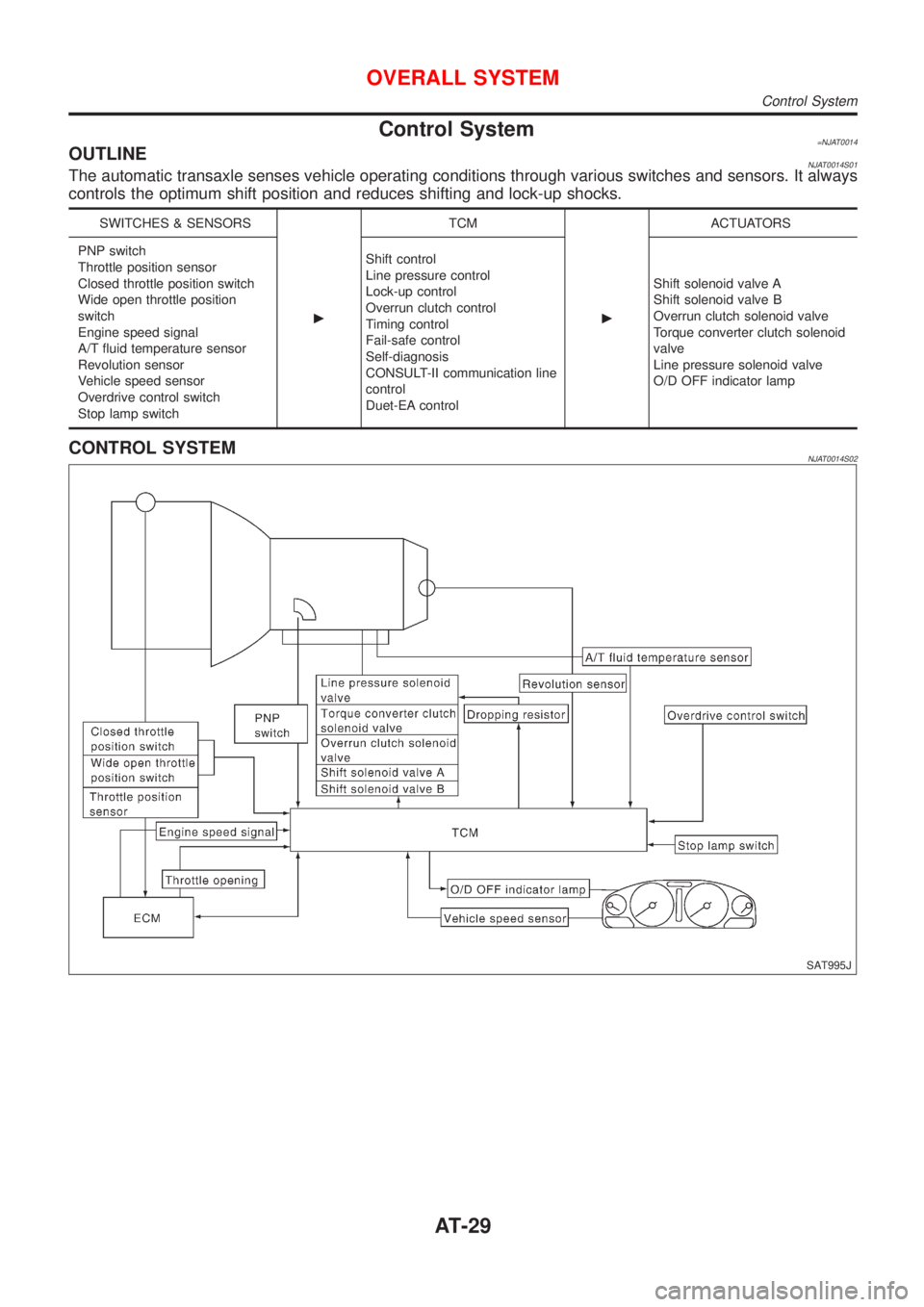
Control System=NJAT0014OUTLINENJAT0014S01The automatic transaxle senses vehicle operating conditions through various switches and sensors. It always
controls the optimum shift position and reduces shifting and lock-up shocks.
SWITCHES & SENSORS
cTCM
cACTUATORS
PNP switch
Throttle position sensor
Closed throttle position switch
Wide open throttle position
switch
Engine speed signal
A/T fluid temperature sensor
Revolution sensor
Vehicle speed sensor
Overdrive control switch
Stop lamp switchShift control
Line pressure control
Lock-up control
Overrun clutch control
Timing control
Fail-safe control
Self-diagnosis
CONSULT-II communication line
control
Duet-EA controlShift solenoid valve A
Shift solenoid valve B
Overrun clutch solenoid valve
Torque converter clutch solenoid
valve
Line pressure solenoid valve
O/D OFF indicator lamp
CONTROL SYSTEMNJAT0014S02
SAT995J
OVERALL SYSTEM
Control System
AT-29
Page 1217 of 2493
SAT003J
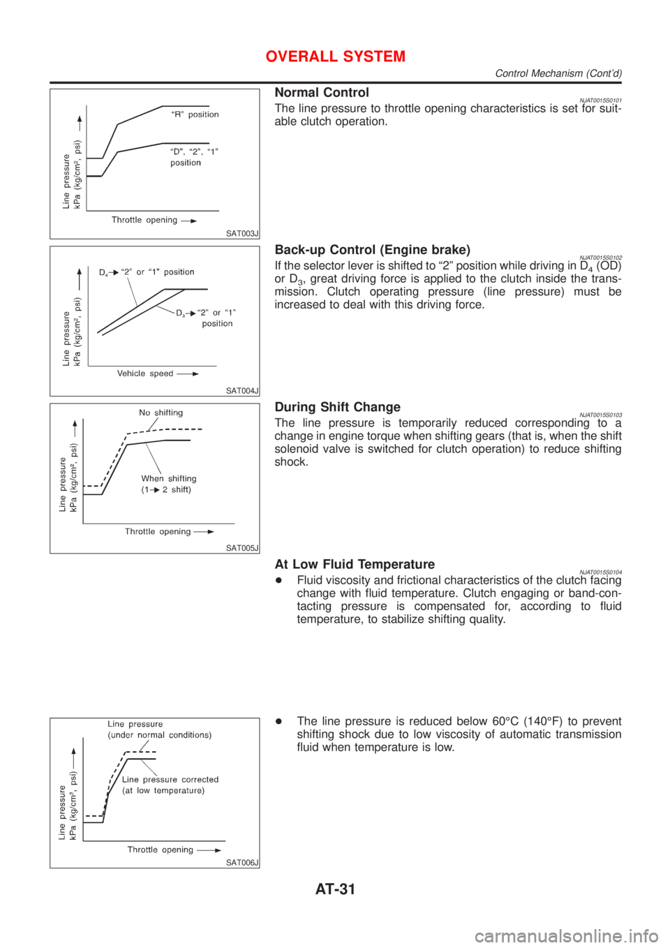
Normal ControlNJAT0015S0101The line pressure to throttle opening characteristics is set for suit-
able clutch operation.
SAT004J
Back-up Control (Engine brake)NJAT0015S0102If the selector lever is shifted to ª2º position while driving in D4(OD)
or D
3, great driving force is applied to the clutch inside the trans-
mission. Clutch operating pressure (line pressure) must be
increased to deal with this driving force.
SAT005J
During Shift ChangeNJAT0015S0103The line pressure is temporarily reduced corresponding to a
change in engine torque when shifting gears (that is, when the shift
solenoid valve is switched for clutch operation) to reduce shifting
shock.
At Low Fluid TemperatureNJAT0015S0104+Fluid viscosity and frictional characteristics of the clutch facing
change with fluid temperature. Clutch engaging or band-con-
tacting pressure is compensated for, according to fluid
temperature, to stabilize shifting quality.
SAT006J
+The line pressure is reduced below 60ÉC (140ÉF) to prevent
shifting shock due to low viscosity of automatic transmission
fluid when temperature is low.
OVERALL SYSTEM
Control Mechanism (Cont'd)
AT-31