Page 1702 of 2493

Precautions When Working On ABSNJBR0140+Use recommended tyres in combination with ABS.
+Please fit tyres or studded tyres, etc. with the same size.
+If different sizes of tyres, or tyres other than the ones rec-
ommended for use with the ABS, are fitted, stopping dis-
tance will increase and control and stability could deterio-
rate.
+When changing brake pads, please use Nissan genuine
parts.
+When fitting radios etc, do not position the radio itself,
antenna, or antenna cables within an area of about 100
mm (3.94 in) of the control unit.
+When doing any work that requires electro-welding, first
remove the control unit.
+Please take care when taking a power supply for the
audio, lamps etc., not to take this from any ABS-related
harness. (Please refer to the electrical wiring diagrams for
ABS-related harnesses)
Wiring Diagrams and Trouble DiagnosisNJBR0003When you read wiring diagrams, refer to the following:
+GI-12, ªHOW TO READ WIRING DIAGRAMSº
+EL-10, ªPOWER SUPPLY ROUTINGº
When you perform trouble diagnosis, refer to the following:
+GI-31, ªHOW TO FOLLOW TEST GROUPS IN TROUBLE DIAGNOSESº
+GI-21, ªHOW TO PERFORM EFFICIENT DIAGNOSIS FOR AN ELECTRICAL INCIDENTº
+On board self-diagnosis is available everywhere except for Europe.
PRECAUTIONS
Precautions When Working On ABS
BR-4
Page 1849 of 2493
Driver Air Bag Module and Spiral Cable
REMOVAL AND INSTALLATION/WITH 4-SPOKE STEERING WHEELNJRS0015
SRS865
SRS566
REMOVALNJRS0016CAUTION:
+Before servicing SRS, turn the ignition switch off, discon-
nect both battery cables and wait at least 3 minutes.
+Always work from the side of driver air bag module.
1. Remove lower lid from steering wheel, and disconnect driver
air bag module connector.
SBF812E
2. Remove side lids and audio steering switch. Using the
TAMPER RESISTANT TORX (Size T30), remove left and right
special bolts. Driver air bag module can then be removed.
SUPPLEMENTAL RESTRAINT SYSTEM (SRS)
Driver Air Bag Module and Spiral Cable
RS-29
Page 1850 of 2493

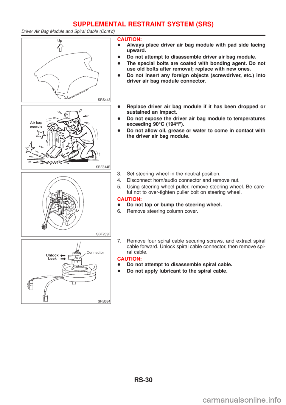
SRS443
CAUTION:
+Always place driver air bag module with pad side facing
upward.
+Do not attempt to disassemble driver air bag module.
+The special bolts are coated with bonding agent. Do not
use old bolts after removal; replace with new ones.
+Do not insert any foreign objects (screwdriver, etc.) into
driver air bag module connector.
SBF814E
+Replace driver air bag module if it has been dropped or
sustained an impact.
+Do not expose the driver air bag module to temperatures
exceeding 90ÉC (194ÉF).
+Do not allow oil, grease or water to come in contact with
the driver air bag module.
SBF239F
3. Set steering wheel in the neutral position.
4. Disconnect horn/audio connector and remove nut.
5. Using steering wheel puller, remove steering wheel. Be care-
ful not to over-tighten puller bolt on steering wheel.
CAUTION:
+Do not tap or bump the steering wheel.
6. Remove steering column cover.
SRS384
7. Remove four spiral cable securing screws, and extract spiral
cable forward. Unlock spiral cable connector, then remove spi-
ral cable.
CAUTION:
+Do not attempt to disassemble spiral cable.
+Do not apply lubricant to the spiral cable.
SUPPLEMENTAL RESTRAINT SYSTEM (SRS)
Driver Air Bag Module and Spiral Cable (Cont'd)
RS-30
Page 1851 of 2493

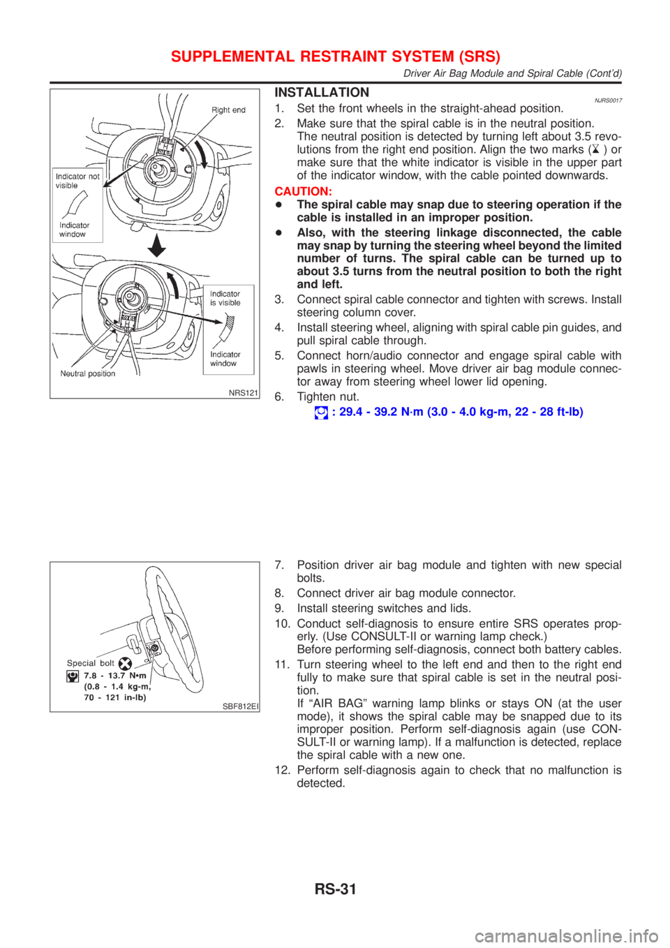
NRS121
INSTALLATIONNJRS00171. Set the front wheels in the straight-ahead position.
2. Make sure that the spiral cable is in the neutral position.
The neutral position is detected by turning left about 3.5 revo-
lutions from the right end position. Align the two marks (
)or
make sure that the white indicator is visible in the upper part
of the indicator window, with the cable pointed downwards.
CAUTION:
+The spiral cable may snap due to steering operation if the
cable is installed in an improper position.
+Also, with the steering linkage disconnected, the cable
may snap by turning the steering wheel beyond the limited
number of turns. The spiral cable can be turned up to
about 3.5 turns from the neutral position to both the right
and left.
3. Connect spiral cable connector and tighten with screws. Install
steering column cover.
4. Install steering wheel, aligning with spiral cable pin guides, and
pull spiral cable through.
5. Connect horn/audio connector and engage spiral cable with
pawls in steering wheel. Move driver air bag module connec-
tor away from steering wheel lower lid opening.
6. Tighten nut.
: 29.4 - 39.2 N´m (3.0 - 4.0 kg-m, 22 - 28 ft-lb)
SBF812EI
7. Position driver air bag module and tighten with new special
bolts.
8. Connect driver air bag module connector.
9. Install steering switches and lids.
10. Conduct self-diagnosis to ensure entire SRS operates prop-
erly. (Use CONSULT-II or warning lamp check.)
Before performing self-diagnosis, connect both battery cables.
11. Turn steering wheel to the left end and then to the right end
fully to make sure that spiral cable is set in the neutral posi-
tion.
If ªAIR BAGº warning lamp blinks or stays ON (at the user
mode), it shows the spiral cable may be snapped due to its
improper position. Perform self-diagnosis again (use CON-
SULT-II or warning lamp). If a malfunction is detected, replace
the spiral cable with a new one.
12. Perform self-diagnosis again to check that no malfunction is
detected.
SUPPLEMENTAL RESTRAINT SYSTEM (SRS)
Driver Air Bag Module and Spiral Cable (Cont'd)
RS-31
Page 2273 of 2493
Inspection=NJEL0221AUDIO UNITNJEL0221S01All voltage inspections are made with:
+Ignition switch ON or ACC
+Audio unit ON
+Audio unit connected (If audio unit is removed for inspection, supply a ground to the case using a jumper
wire.)
ANTENNANJEL0221S02Using a jumper wire, clip an auxiliary ground between antenna and body.
+If reception improves, check antenna ground (at body surface).
+If reception does not improve, check main feeder cable for short circuit or open circuit.
AUDIO
Inspection
EL-161