2001 NISSAN ALMERA N16 seat adjustment
[x] Cancel search: seat adjustmentPage 80 of 2493

REPLACEMENT OF CONNECTING ROD
BUSHING (SMALL END)
..........................................60
FLYWHEEL/DRIVE PLATE RUNOUT........................60
Assembly ...................................................................60
PISTON..................................................................60
CRANKSHAFT.........................................................61
SERVICE DATA AND SPECIFICATIONS (SDS).........64
General Specifications ...............................................64
Compression Pressure ..............................................64
Belt Deflection............................................................64
Spark Plug .................................................................65
Cylinder Head ............................................................65
Valve ..........................................................................66
VALVE....................................................................66
VALVE SPRING.......................................................66
VALVE LIFTER........................................................66
VALVE CLEARANCE................................................67
VALVE GUIDE.........................................................67
AVAILABLE SHIMS..................................................67
VALVE SEAT...........................................................70
VALVE SEAT RESURFACE LIMIT.............................71
Camshaft and Camshaft Bearing ..............................71
Cylinder Block ............................................................72
Piston, Piston Ring and Piston Pin ...........................73
PISTON..................................................................73
PISTON RING.........................................................73
PISTON PIN............................................................73
Connecting Rod .........................................................74
Crankshaft..................................................................74
Main Bearing..............................................................74
STANDARD.............................................................74
UNDERSIZE............................................................74
Connecting Rod Bearing ...........................................75
STANDARD SIZE....................................................75
UNDERSIZE............................................................75
Bearing Clearance .....................................................75
Miscellaneous Components.......................................75
YD
PRECAUTIONS.............................................................76
Parts Requiring Angular Tightening ...........................76
Liquid Gasket Application Procedure ........................76
PREPARATION.............................................................77
Special Service Tools ................................................77
Commercial Service Tools .........................................79
NOISE, VIBRATION AND HARSHNESS (NVH)
TROUBLESHOOTING...................................................81
NVH Troubleshooting - Engine Noise .......................81
MEASUREMENT OF COMPRESSION PRESSURE....82
DRIVE BELTS................................................................84
Inspection...................................................................84
Adjustment .................................................................84
AIR CONDITIONER COMPRESSOR BELT................85
ALTERNATOR & WATER PUMP BELT.....................85
Removal .....................................................................85
Installation ..................................................................86
AIR CLEANER...............................................................87
Changing Air Cleaner Filter .......................................87
VISCOUS PAPER TYPE...........................................87
OIL PAN.........................................................................88
Components...............................................................88
Removal .....................................................................88
Installation ..................................................................90
TIMING CHAIN..............................................................93
Secondary Timing Chain ...........................................93
REMOVAL...............................................................93
INSPECTION...........................................................95
INSTALLATION........................................................95
Primary Timing Chain ................................................98
REMOVAL...............................................................99
INSPECTION.........................................................101
INSTALLATION......................................................101
INTAKE MANIFOLD....................................................106
Removal and Installation .........................................106
PREPARATIVE WORK...........................................106
FUEL PIPING........................................................107
INTAKE MANIFOLD...............................................107
EGR VOLUME CONTROL VALVE...........................107
WATER HOSE.......................................................107
Inspection.................................................................108
INTAKE MANIFOLD...............................................108
CATALYST..................................................................109
Removal and Installation .........................................109
PREPARATIVE WORK...........................................109
CATALYST............................................................109
GUSSET............................................................... 110
EXHAUST MANIFOLD, TURBOCHARGER............... 111
Removal and Installation ......................................... 111
PREPARATIVE WORK........................................... 111
EXHAUST MANIFOLD AND TURBOCHARGER....... 111
EXHAUST MANIFOLD GASKET............................. 112
Disassembly and Assembly ..................................... 112
TURBOCHARGER................................................. 112
Inspection................................................................. 113
EXHAUST MANIFOLD........................................... 113
TURBOCHARGER................................................. 113
ROCKER COVER........................................................ 116
Removal and Installation ......................................... 116
PREPARATIVE WORK........................................... 116
ROCKER COVER.................................................. 116
CYLINDER HEAD........................................................ 118
Components............................................................. 118
Removal ................................................................... 119
PREPARATIVE WORK........................................... 119
CAMSHAFT........................................................... 119
CYLINDER HEAD..................................................120
Disassembly.............................................................120
Inspection.................................................................121
CONTENTS(Cont'd)
EM-2
Page 1035 of 2493
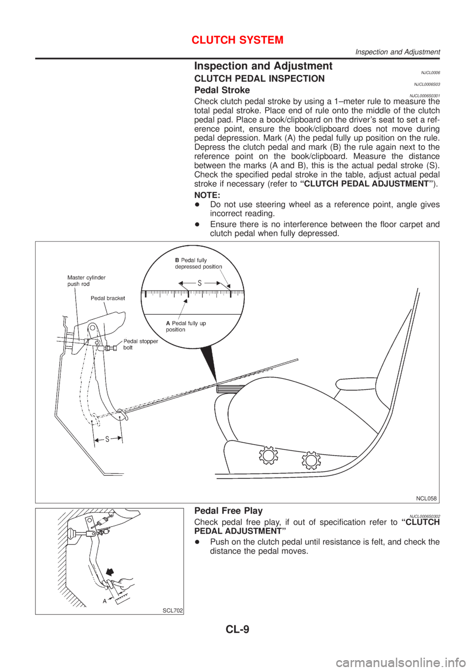
Inspection and AdjustmentNJCL0006CLUTCH PEDAL INSPECTIONNJCL0006S03Pedal StrokeNJCL0006S0301Check clutch pedal stroke by using a 1±meter rule to measure the
total pedal stroke. Place end of rule onto the middle of the clutch
pedal pad. Place a book/clipboard on the driver's seat to set a ref-
erence point, ensure the book/clipboard does not move during
pedal depression. Mark (A) the pedal fully up position on the rule.
Depress the clutch pedal and mark (B) the rule again next to the
reference point on the book/clipboard. Measure the distance
between the marks (A and B), this is the actual pedal stroke (S).
Check the specified pedal stroke in the table, adjust actual pedal
stroke if necessary (refer toªCLUTCH PEDAL ADJUSTMENTº).
NOTE:
+Do not use steering wheel as a reference point, angle gives
incorrect reading.
+Ensure there is no interference between the floor carpet and
clutch pedal when fully depressed.
NCL058
SCL702
Pedal Free PlayNJCL0006S0302Check pedal free play, if out of specification refer toªCLUTCH
PEDAL ADJUSTMENTº
+Push on the clutch pedal until resistance is felt, and check the
distance the pedal moves.
CLUTCH SYSTEM
Inspection and Adjustment
CL-9
Page 1100 of 2493
SMT600-A
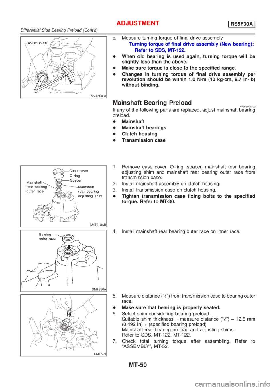
c. Measure turning torque of final drive assembly.
Turning torque of final drive assembly (New bearing):
Refer to SDS, MT-122.
+When old bearing is used again, turning torque will be
slightly less than the above.
+Make sure torque is close to the specified range.
+Changes in turning torque of final drive assembly per
revolution should be within 1.0 N´m (10 kg-cm, 8.7 in-lb)
without binding.
Mainshaft Bearing PreloadNJMT0091S02If any of the following parts are replaced, adjust mainshaft bearing
preload.
+Mainshaft
+Mainshaft bearings
+Clutch housing
+Transmission case
SMT613AB
1. Remove case cover, O-ring, spacer, mainshaft rear bearing
adjusting shim and mainshaft rear bearing outer race from
transmission case.
2. Install mainshaft assembly on clutch housing.
3. Install transmission case on clutch housing.
+Tighten transmission case fixing bolts to the specified
torque. Refer to MT-30.
SMT650A
4. Install mainshaft rear bearing outer race on inner race.
SMT599
5. Measure distance (ª!º) from transmission case to bearing outer
race.
+Make sure that bearing is properly seated.
6. Select shim considering bearing preload.
Suitable shim thickness = measure distance (ª!º) þ 12.5 mm
(0.492 in) + (specified bearing preload)
Mainshaft rear bearing preload and adjusting shims:
Refer to SDS, MT-122, MT-122.
7. Check total turning torque after assembling. Refer to
ªASSEMBLYº, MT-52.
ADJUSTMENTRS5F30A
Differential Side Bearing Preload (Cont'd)
MT-50
Page 1163 of 2493
SMT644AA
2. Reinstall mainshaft rear bearing outer race without shims.
3. Clean mating surfaces of clutch housing and transmission
case with solvent.
4. Install mainshaft and mainshaft front bearing outer race into
transmission case. Turn mainshaft while holding bearing outer
race so that bearings are properly seated.
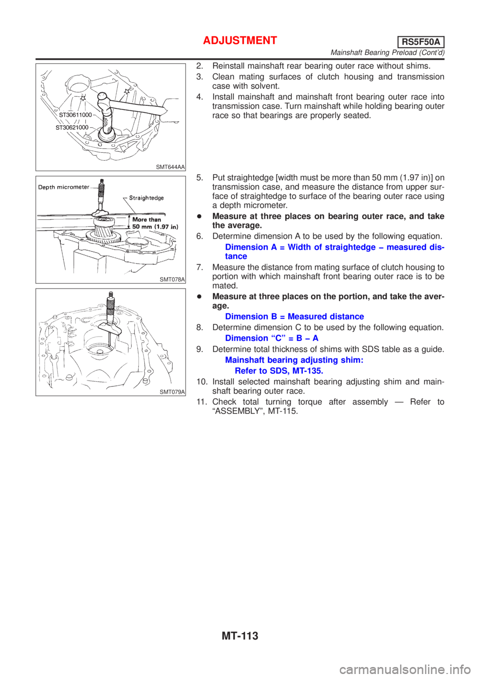
SMT078A
SMT079A
5. Put straightedge [width must be more than 50 mm (1.97 in)] on
transmission case, and measure the distance from upper sur-
face of straightedge to surface of the bearing outer race using
a depth micrometer.
+Measure at three places on bearing outer race, and take
the average.
6. Determine dimension A to be used by the following equation.
Dimension A = Width of straightedge þ measured dis-
tance
7. Measure the distance from mating surface of clutch housing to
portion with which mainshaft front bearing outer race is to be
mated.
+Measure at three places on the portion, and take the aver-
age.
Dimension B = Measured distance
8. Determine dimension C to be used by the following equation.
Dimension ªCº=BþA
9. Determine total thickness of shims with SDS table as a guide.
Mainshaft bearing adjusting shim:
Refer to SDS, MT-135.
10. Install selected mainshaft bearing adjusting shim and main-
shaft bearing outer race.
11. Check total turning torque after assembly Ð Refer to
ªASSEMBLYº, MT-115.
ADJUSTMENTRS5F50A
Mainshaft Bearing Preload (Cont'd)
MT-113
Page 1616 of 2493
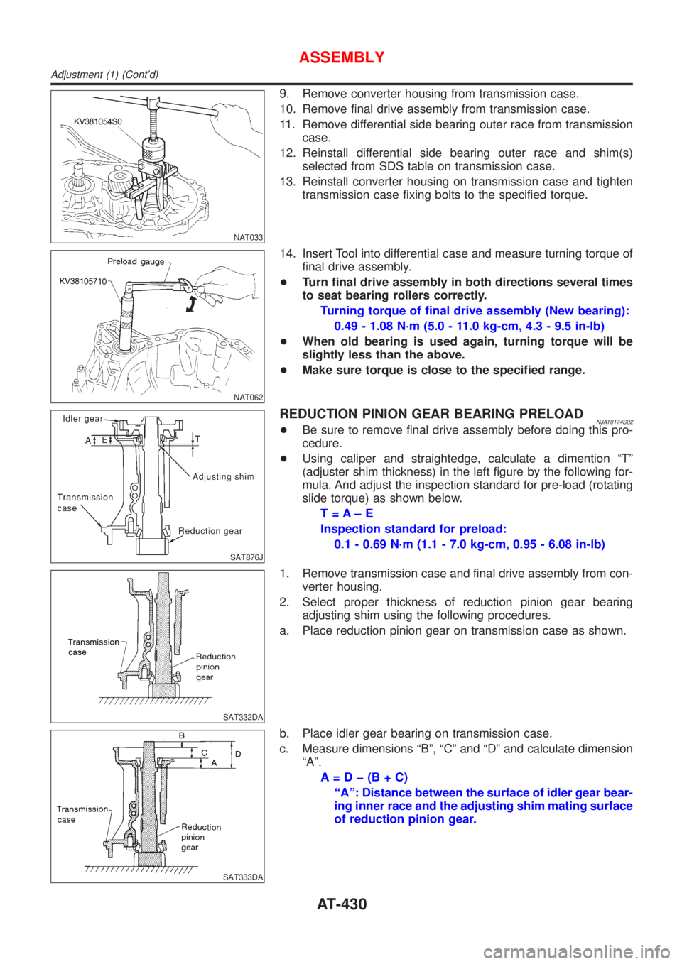
NAT033
9. Remove converter housing from transmission case.
10. Remove final drive assembly from transmission case.
11. Remove differential side bearing outer race from transmission
case.
12. Reinstall differential side bearing outer race and shim(s)
selected from SDS table on transmission case.
13. Reinstall converter housing on transmission case and tighten
transmission case fixing bolts to the specified torque.
NAT062
14. Insert Tool into differential case and measure turning torque of
final drive assembly.
+Turn final drive assembly in both directions several times
to seat bearing rollers correctly.
Turning torque of final drive assembly (New bearing):
0.49 - 1.08 N´m (5.0 - 11.0 kg-cm, 4.3 - 9.5 in-lb)
+When old bearing is used again, turning torque will be
slightly less than the above.
+Make sure torque is close to the specified range.
SAT876J
REDUCTION PINION GEAR BEARING PRELOADNJAT0174S02+Be sure to remove final drive assembly before doing this pro-
cedure.
+Using caliper and straightedge, calculate a dimention ªTº
(adjuster shim thickness) in the left figure by the following for-
mula. And adjust the inspection standard for pre-load (rotating
slide torque) as shown below.
T=A±E
Inspection standard for preload:
0.1 - 0.69 N´m (1.1 - 7.0 kg-cm, 0.95 - 6.08 in-lb)
SAT332DA
1. Remove transmission case and final drive assembly from con-
verter housing.
2. Select proper thickness of reduction pinion gear bearing
adjusting shim using the following procedures.
a. Place reduction pinion gear on transmission case as shown.
SAT333DA
b. Place idler gear bearing on transmission case.
c. Measure dimensions ªBº, ªCº and ªDº and calculate dimension
ªAº.
A=Dþ(B+C)
ªAº: Distance between the surface of idler gear bear-
ing inner race and the adjusting shim mating surface
of reduction pinion gear.
ASSEMBLY
Adjustment (1) (Cont'd)
AT-430
Page 1618 of 2493
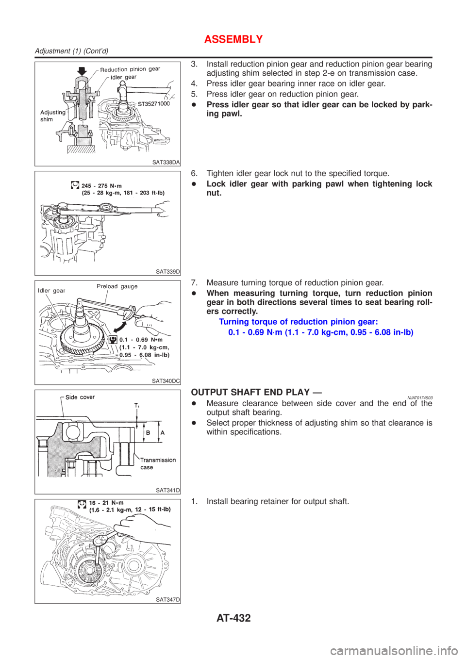
SAT338DA
3. Install reduction pinion gear and reduction pinion gear bearing
adjusting shim selected in step 2-e on transmission case.
4. Press idler gear bearing inner race on idler gear.
5. Press idler gear on reduction pinion gear.
+Press idler gear so that idler gear can be locked by park-
ing pawl.
SAT339D
6. Tighten idler gear lock nut to the specified torque.
+Lock idler gear with parking pawl when tightening lock
nut.
SAT340DC
7. Measure turning torque of reduction pinion gear.
+When measuring turning torque, turn reduction pinion
gear in both directions several times to seat bearing roll-
ers correctly.
Turning torque of reduction pinion gear:
0.1 - 0.69 N´m (1.1 - 7.0 kg-cm, 0.95 - 6.08 in-lb)
SAT341D
OUTPUT SHAFT END PLAY ÐNJAT0174S03+Measure clearance between side cover and the end of the
output shaft bearing.
+Select proper thickness of adjusting shim so that clearance is
within specifications.
SAT347D
1. Install bearing retainer for output shaft.
ASSEMBLY
Adjustment (1) (Cont'd)
AT-432
Page 1699 of 2493
BRAKE SYSTEM
SECTION
BR
CONTENTS
PRECAUTIONS...............................................................3
Supplemental Restraint System (SRS)²AIR
BAG²and²SEAT BELT PRE-TENSIONER²...............3
Precautions for Brake System .....................................3
Precautions When Working On ABS ...........................4
Wiring Diagrams and Trouble Diagnosis .....................4
PREPARATION...............................................................5
Commercial Service Tools ...........................................5
NOISE, VIBRATION AND HARSHNESS (NVH)
TROUBLESHOOTING.....................................................6
NVH Troubleshooting Chart.........................................6
ON-VEHICLE SERVICE..................................................7
Checking Brake Fluid Level.........................................7
Checking Brake Line ...................................................7
Changing Brake Fluid ..................................................7
Brake Burnishing Procedure........................................7
Bleeding Brake System ...............................................8
BRAKE HYDRAULIC LINE.............................................9
Hydraulic Circuit...........................................................9
Removal .......................................................................9
Inspection...................................................................10
Installation ..................................................................10
DUAL PROPORTIONING VALVE................................. 11
Dual Proportioning Valve ........................................... 11
INSPECTION........................................................... 11
REMOVAL AND INSTALLATION (BUILT-IN TYPE)...... 11
BRAKE PEDAL AND BRACKET..................................12
Removal and Installation ...........................................12
Inspection...................................................................12
Adjustment .................................................................12
MASTER CYLINDER (NABCO)....................................14
Removal .....................................................................14
Disassembly...............................................................15
Inspection...................................................................15
Assembly ...................................................................15
Installation ..................................................................16
MASTER CYLINDER [BOSCH (NABCO)]...................17
Removal .....................................................................17
Disassembly...............................................................17Inspection...................................................................18
Assembly ...................................................................18
Installation ..................................................................19
BRAKE BOOSTER........................................................20
On-vehicle Service.....................................................20
OPERATING CHECK...............................................20
AIRTIGHT CHECK...................................................20
Removal .....................................................................20
Inspection...................................................................20
OUTPUT ROD LENGTH CHECK..............................20
Installation ..................................................................21
VACUUM HOSE.............................................................22
Removal and Installation ...........................................22
Inspection...................................................................22
HOSES AND CONNECTORS...................................22
CHECK VALVE........................................................22
VACUUM PUMP............................................................23
Removal .....................................................................23
Installation ..................................................................24
Inspection...................................................................24
Component ................................................................25
Disassembly...............................................................25
Assembly ...................................................................25
FRONT DISC BRAKE...................................................27
Component ................................................................27
Pad Replacement ......................................................27
Removal .....................................................................28
Disassembly...............................................................28
Inspection...................................................................28
CALIPER.................................................................28
ROTOR...................................................................29
Assembly ...................................................................30
Installation ..................................................................30
REAR DRUM BRAKE...................................................31
Components...............................................................31
Removal .....................................................................31
Inspection - Wheel Cylinder ......................................32
Wheel Cylinder Overhaul...........................................33
Inspection - Drum ......................................................33
Page 1791 of 2493
STEERING SYSTEM
SECTION
ST
CONTENTS
PRECAUTIONS...............................................................2
Supplemental Restraint System (SRS)²AIR
BAG²and²SEAT BELT PRE-TENSIONER²...............2
Precautions for Steering System .................................2
PREPARATION...............................................................3
Special Service Tools ..................................................3
Commercial Service Tool .............................................4
NOISE, VIBRATION AND HARSHNESS (NVH)
TROUBLESHOOTING.....................................................5
NVH Troubleshooting Chart.........................................5
ON-VEHICLE SERVICE..................................................6
Checking Steering Wheel Play ....................................6
Checking Neutral Position on Steering Wheel ............6
PRE-CHECKING........................................................6
CHECKING...............................................................6
Front Wheel Turning Angle ..........................................6
Checking Gear Housing Movement ............................6
Checking and Adjusting Drive Belts ............................7
Checking Steering Gear and Linkage .........................7
STEERING GEAR......................................................7
STEERING LINKAGE.................................................7
Checking Fluid Level ...................................................7
Checking Fluid Leakage ..............................................7
Bleeding Hydraulic System..........................................8
Checking Steering Wheel Turning Force ....................8
Checking Hydraulic System.........................................9
STEERING WHEEL AND STEERING COLUMN.........10
Components...............................................................10
Removal and Installation ...........................................10
STEERING WHEEL.................................................10
STEERING COLUMN............................................... 11Disassembly and Assembly .......................................13
Inspection...................................................................14
TILT MECHANISM...................................................14
POWER STEERING GEAR AND LINKAGE................15
Components...............................................................15
Removal and Installation ...........................................16
Disassembly...............................................................17
Inspection...................................................................18
BOOT.....................................................................18
RACK.....................................................................18
GEAR SUB-ASSEMBLY...........................................18
GEAR HOUSING CYLINDER....................................18
TIE-ROD OUTER AND INNER SOCKETS..................19
Assembly ...................................................................19
Adjustment .................................................................22
POWER STEERING OIL PUMP (QG ENGINE)...........24
Component Description .............................................24
POWER STEERING OIL PUMP (YD ENGINE)............25
Components...............................................................25
Pre-disassembly Inspection .......................................25
Removal and Installation ...........................................26
Disassembly...............................................................26
Inspection...................................................................27
Assembly ...................................................................28
SERVICE DATA AND SPECIFICATIONS (SDS).........29
General Specifications ...............................................29
Steering Wheel ..........................................................29
Steering Column ........................................................29
Steering Gear and Linkage .......................................30
Power Steering ..........................................................30