2001 NISSAN ALMERA N16 seat adjustment
[x] Cancel search: seat adjustmentPage 1895 of 2493
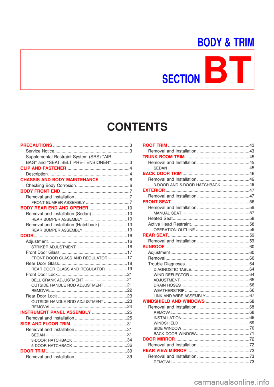
BODY & TRIM
SECTION
BT
CONTENTS
PRECAUTIONS...............................................................3
Service Notice..............................................................3
Supplemental Restraint System (SRS)²AIR
BAG²and²SEAT BELT PRE-TENSIONER²...............3
CLIP AND FASTENER....................................................4
Description ...................................................................4
CHASSIS AND BODY MAINTENANCE.........................6
Checking Body Corrosion ............................................6
BODY FRONT END.........................................................7
Removal and Installation .............................................7
FRONT BUMPER ASSEMBLY....................................7
BODY REAR END AND OPENER................................10
Removal and Installation (Sedan) .............................10
REAR BUMPER ASSEMBLY....................................10
Removal and Installation (Hatchback).......................13
REAR BUMPER ASSEMBLY....................................13
DOOR.............................................................................16
Adjustment .................................................................16
STRIKER ADJUSTMENT..........................................16
Front Door Glass .......................................................17
FRONT DOOR GLASS AND REGULATOR................17
Rear Door Glass ........................................................18
REAR DOOR GLASS AND REGULATOR..................19
Front Door Lock .........................................................21
BELL CRANK ADJUSTMENT....................................21
OUTSIDE HANDLE ROD ADJUSTMENT...................21
REMOVAL...............................................................22
Rear Door Lock .........................................................23
OUTSIDE HANDLE ROD ADJUSTMENT...................23
REMOVAL...............................................................24
INSTRUMENT PANEL ASSEMBLY.............................25
Removal and Installation ...........................................25
SIDE AND FLOOR TRIM...............................................31
Removal and Installation ...........................................31
SEDAN...................................................................31
3-DOOR HATCHBACK.............................................34
5-DOOR HATCHBACK.............................................36
DOOR TRIM...................................................................39
Removal and Installation ...........................................39ROOF TRIM...................................................................43
Removal and Installation ...........................................43
TRUNK ROOM TRIM.....................................................45
Removal and Installation ...........................................45
SEDAN...................................................................45
BACK DOOR TRIM.......................................................46
Removal and Installation ...........................................46
3-DOOR AND 5-DOOR HATCHBACK.......................46
EXTERIOR.....................................................................47
Removal and Installation ...........................................47
FRONT SEAT................................................................56
Removal and Installation ...........................................56
MANUAL SEAT........................................................57
Heated Seat ...............................................................58
Active Head Restraint ................................................58
OPERATION OUTLINE............................................58
REAR SEAT...................................................................59
Removal and Installation ...........................................59
SUNROOF......................................................................60
Adjustment .................................................................60
Removal .....................................................................60
Trouble Diagnoses.....................................................64
DIAGNOSTIC TABLE................................................64
WIND DEFLECTOR.................................................64
ADJUSTMENT.........................................................65
DRAIN HOSES........................................................66
WEATHERSTRIP.....................................................66
LINK AND WIRE ASSEMBLY....................................67
WINDSHIELD AND WINDOWS....................................68
Removal and Installation ...........................................68
REMOVAL...............................................................68
INSTALLATION........................................................68
WINDSHIELD..........................................................69
SIDE WINDOW........................................................70
BACK DOOR WINDOW............................................71
DOOR MIRROR.............................................................72
Removal and Installation ...........................................72
REAR VIEW MIRROR...................................................73
Removal and Installation ...........................................73
REMOVAL...............................................................73
Page 2077 of 2493
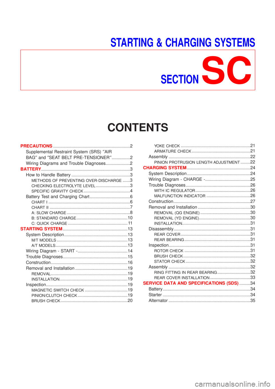
STARTING & CHARGING SYSTEMS
SECTION
SC
CONTENTS
PRECAUTIONS...............................................................2
Supplemental Restraint System (SRS)²AIR
BAG²and²SEAT BELT PRE-TENSIONER²...............2
Wiring Diagrams and Trouble Diagnoses....................2
BATTERY.........................................................................3
How to Handle Battery ................................................3
METHODS OF PREVENTING OVER-DISCHARGE......3
CHECKING ELECTROLYTE LEVEL............................3
SPECIFIC GRAVITY CHECK......................................4
Battery Test and Charging Chart .................................6
CHART I...................................................................6
CHART II..................................................................7
A: SLOW CHARGE....................................................8
B: STANDARD CHARGE..........................................10
C: QUICK CHARGE................................................. 11
STARTING SYSTEM.....................................................13
System Description ....................................................13
M/T MODELS..........................................................13
A/T MODELS...........................................................13
Wiring Diagram - START -.........................................14
Trouble Diagnoses.....................................................15
Construction ...............................................................16
Removal and Installation ...........................................19
REMOVAL...............................................................19
INSTALLATION........................................................19
Inspection...................................................................19
MAGNETIC SWITCH CHECK...................................19
PINION/CLUTCH CHECK.........................................19
BRUSH CHECK.......................................................20
YOKE CHECK.........................................................21
ARMATURE CHECK................................................21
Assembly ...................................................................22
PINION PROTRUSION LENGTH ADJUSTMENT........22
CHARGING SYSTEM....................................................24
System Description ....................................................24
Wiring Diagram - CHARGE -.....................................25
Trouble Diagnoses.....................................................26
WITH IC REGULATOR.............................................26
MALFUNCTION INDICATOR....................................26
Construction ...............................................................27
Removal and Installation ...........................................30
REMOVAL (QG ENGINE).........................................30
REMOVAL (YD ENGINE)..........................................30
INSTALLATION........................................................31
Disassembly...............................................................31
REAR COVER.........................................................31
REAR BEARING......................................................31
Inspection...................................................................31
ROTOR CHECK......................................................31
BRUSH CHECK.......................................................32
STATOR CHECK.....................................................32
Assembly ...................................................................32
RING FITTING IN REAR BEARING...........................32
REAR COVER INSTALLATION.................................33
SERVICE DATA AND SPECIFICATIONS (SDS).........34
Battery........................................................................34
Starter ........................................................................34
Alternator ...................................................................35
Page 2113 of 2493
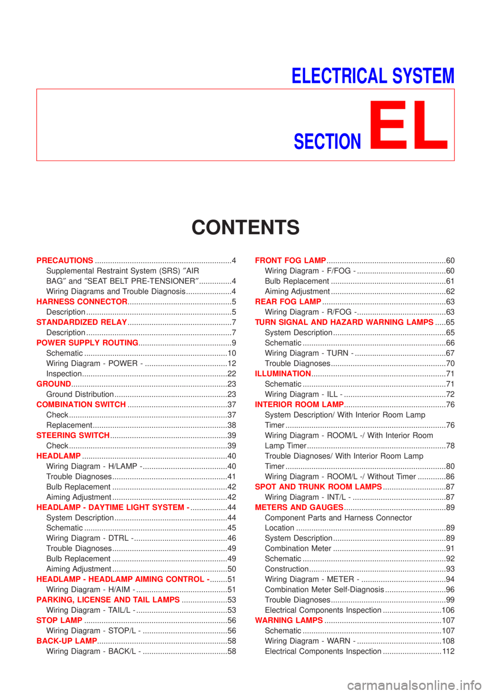
ELECTRICAL SYSTEM
SECTION
EL
CONTENTS
PRECAUTIONS...............................................................4
Supplemental Restraint System (SRS)²AIR
BAG²and²SEAT BELT PRE-TENSIONER²...............4
Wiring Diagrams and Trouble Diagnosis .....................4
HARNESS CONNECTOR................................................5
Description ...................................................................5
STANDARDIZED RELAY................................................7
Description ...................................................................7
POWER SUPPLY ROUTING...........................................9
Schematic ..................................................................10
Wiring Diagram - POWER - ......................................12
Inspection...................................................................22
GROUND........................................................................23
Ground Distribution ....................................................23
COMBINATION SWITCH..............................................37
Check .........................................................................37
Replacement ..............................................................38
STEERING SWITCH......................................................39
Check .........................................................................39
HEADLAMP...................................................................40
Wiring Diagram - H/LAMP -.......................................40
Trouble Diagnoses.....................................................41
Bulb Replacement .....................................................42
Aiming Adjustment .....................................................42
HEADLAMP - DAYTIME LIGHT SYSTEM -.................44
System Description ....................................................44
Schematic ..................................................................45
Wiring Diagram - DTRL - ...........................................46
Trouble Diagnoses.....................................................49
Bulb Replacement .....................................................49
Aiming Adjustment .....................................................50
HEADLAMP - HEADLAMP AIMING CONTROL -........51
Wiring Diagram - H/AIM - ..........................................51
PARKING, LICENSE AND TAIL LAMPS.....................53
Wiring Diagram - TAIL/L - ..........................................53
STOP LAMP..................................................................56
Wiring Diagram - STOP/L - .......................................56
BACK-UP LAMP............................................................58
Wiring Diagram - BACK/L - .......................................58FRONT FOG LAMP.......................................................60
Wiring Diagram - F/FOG - .........................................60
Bulb Replacement .....................................................61
Aiming Adjustment .....................................................62
REAR FOG LAMP.........................................................63
Wiring Diagram - R/FOG -.........................................63
TURN SIGNAL AND HAZARD WARNING LAMPS.....65
System Description ....................................................65
Schematic ..................................................................66
Wiring Diagram - TURN - ..........................................67
Trouble Diagnoses.....................................................70
ILLUMINATION..............................................................71
Schematic ..................................................................71
Wiring Diagram - ILL - ...............................................72
INTERIOR ROOM LAMP...............................................76
System Description/ With Interior Room Lamp
Timer ..........................................................................76
Wiring Diagram - ROOM/L -/ With Interior Room
Lamp Timer ................................................................78
Trouble Diagnoses/ With Interior Room Lamp
Timer ..........................................................................80
Wiring Diagram - ROOM/L -/ Without Timer .............86
SPOT AND TRUNK ROOM LAMPS.............................87
Wiring Diagram - INT/L - ...........................................87
METERS AND GAUGES...............................................89
Component Parts and Harness Connector
Location .....................................................................89
System Description ....................................................89
Combination Meter ....................................................91
Schematic ..................................................................92
Construction ...............................................................93
Wiring Diagram - METER - .......................................94
Combination Meter Self-Diagnosis ............................96
Trouble Diagnoses.....................................................99
Electrical Components Inspection ...........................106
WARNING LAMPS......................................................107
Schematic ................................................................107
Wiring Diagram - WARN - .......................................108
Electrical Components Inspection ........................... 112
Page 2114 of 2493
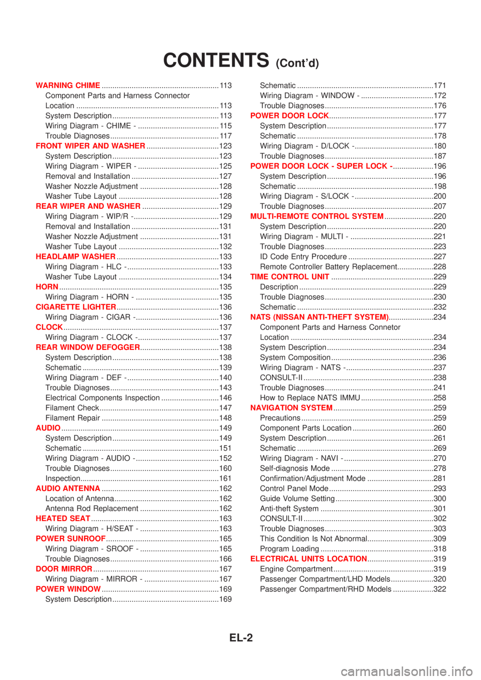
WARNING CHIME....................................................... 113
Component Parts and Harness Connector
Location ................................................................... 113
System Description .................................................. 113
Wiring Diagram - CHIME - ...................................... 115
Trouble Diagnoses................................................... 117
FRONT WIPER AND WASHER..................................123
System Description ..................................................123
Wiring Diagram - WIPER - ......................................125
Removal and Installation .........................................127
Washer Nozzle Adjustment .....................................128
Washer Tube Layout ...............................................128
REAR WIPER AND WASHER....................................129
Wiring Diagram - WIP/R -........................................129
Removal and Installation .........................................131
Washer Nozzle Adjustment .....................................131
Washer Tube Layout ...............................................132
HEADLAMP WASHER................................................133
Wiring Diagram - HLC - ...........................................133
Washer Tube Layout ...............................................134
HORN...........................................................................135
Wiring Diagram - HORN - .......................................135
CIGARETTE LIGHTER................................................136
Wiring Diagram - CIGAR -.......................................136
CLOCK.........................................................................137
Wiring Diagram - CLOCK -......................................137
REAR WINDOW DEFOGGER.....................................138
System Description ..................................................138
Schematic ................................................................139
Wiring Diagram - DEF - ...........................................140
Trouble Diagnoses...................................................143
Electrical Components Inspection ...........................146
Filament Check ........................................................147
Filament Repair .......................................................148
AUDIO..........................................................................149
System Description ..................................................149
Schematic ................................................................151
Wiring Diagram - AUDIO - .......................................152
Trouble Diagnoses...................................................160
Inspection.................................................................161
AUDIO ANTENNA.......................................................162
Location of Antenna .................................................162
Antenna Rod Replacement .....................................162
HEATED SEAT............................................................163
Wiring Diagram - H/SEAT - .....................................163
POWER SUNROOF.....................................................165
Wiring Diagram - SROOF - .....................................165
Trouble Diagnoses...................................................166
DOOR MIRROR...........................................................167
Wiring Diagram - MIRROR - ...................................167
POWER WINDOW.......................................................169
System Description ..................................................169Schematic ................................................................171
Wiring Diagram - WINDOW - ..................................172
Trouble Diagnoses...................................................176
POWER DOOR LOCK.................................................177
System Description ..................................................177
Schematic ................................................................178
Wiring Diagram - D/LOCK -.....................................180
Trouble Diagnoses...................................................187
POWER DOOR LOCK - SUPER LOCK -...................196
System Description ..................................................196
Schematic ................................................................198
Wiring Diagram - S/LOCK - .....................................200
Trouble Diagnoses...................................................207
MULTI-REMOTE CONTROL SYSTEM.......................220
System Description ..................................................220
Wiring Diagram - MULTI - .......................................221
Trouble Diagnoses...................................................223
ID Code Entry Procedure ........................................227
Remote Controller Battery Replacement.................228
TIME CONTROL UNIT................................................229
Description ...............................................................229
Trouble Diagnoses...................................................230
Schematic ................................................................232
NATS (NISSAN ANTI-THEFT SYSTEM).....................234
Component Parts and Harness Connetor
Location ...................................................................234
System Description ..................................................234
System Composition ................................................236
Wiring Diagram - NATS -.........................................237
CONSULT-II .............................................................238
Trouble Diagnoses...................................................241
How to Replace NATS IMMU ..................................258
NAVIGATION SYSTEM...............................................259
Precautions ..............................................................259
Component Parts Location ......................................260
System Description ..................................................261
Schematic ................................................................269
Wiring Diagram - NAVI - ..........................................270
Self-diagnosis Mode ................................................278
Confirmation/Adjustment Mode ...............................281
Control Panel Mode .................................................293
Guide Volume Setting ..............................................300
Anti-theft System .....................................................301
CONSULT-II .............................................................302
Trouble Diagnoses...................................................303
This Condition Is Not Abnormal...............................309
Program Loading .....................................................318
ELECTRICAL UNITS LOCATION...............................319
Engine Compartment ...............................................319
Passenger Compartment/LHD Models ....................320
Passenger Compartment/RHD Models ...................322
CONTENTS(Cont'd)
EL-2
Page 2174 of 2493
SEL976W
SEL480X
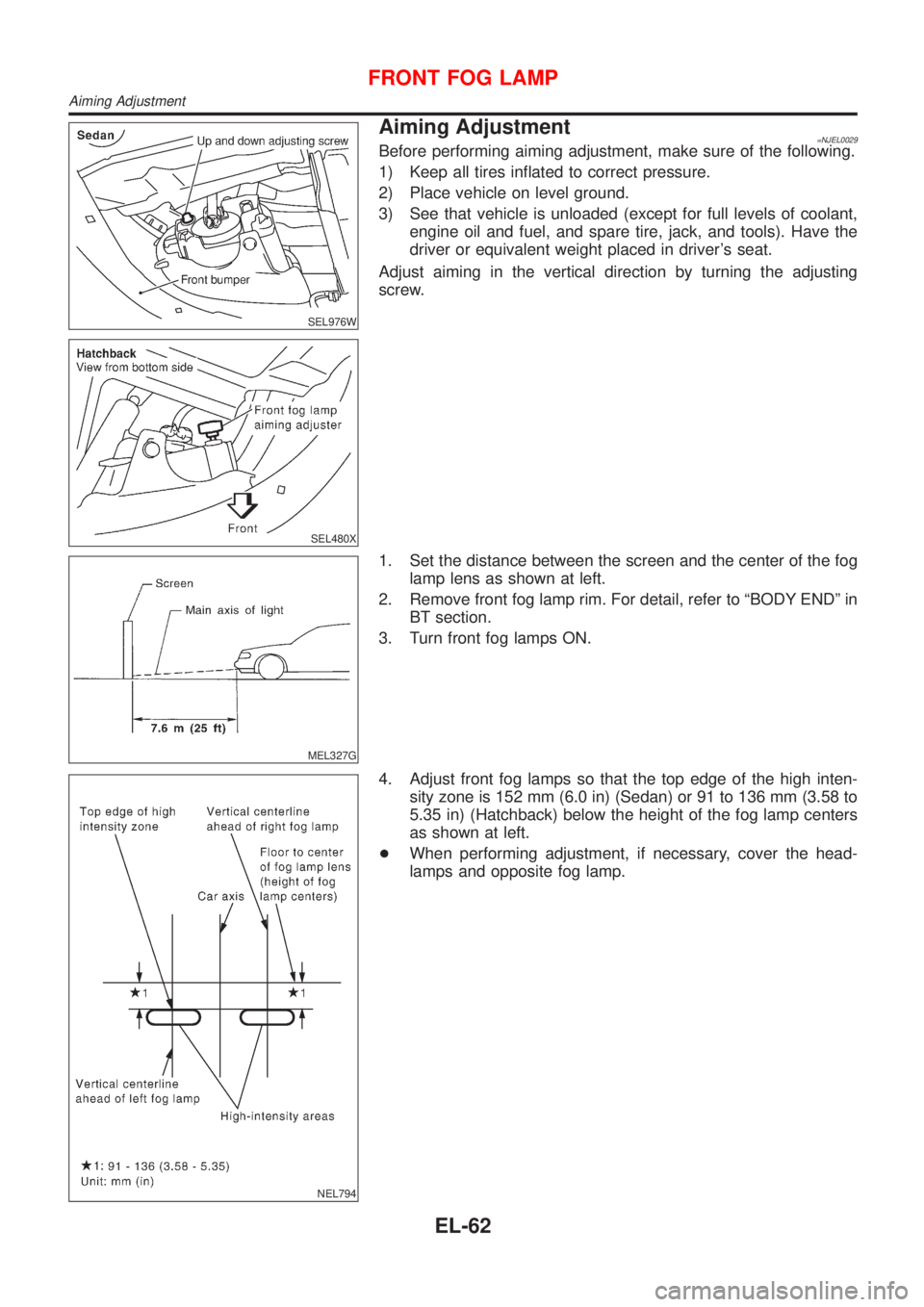
Aiming Adjustment=NJEL0029Before performing aiming adjustment, make sure of the following.
1) Keep all tires inflated to correct pressure.
2) Place vehicle on level ground.
3) See that vehicle is unloaded (except for full levels of coolant,
engine oil and fuel, and spare tire, jack, and tools). Have the
driver or equivalent weight placed in driver's seat.
Adjust aiming in the vertical direction by turning the adjusting
screw.
MEL327G
1. Set the distance between the screen and the center of the fog
lamp lens as shown at left.
2. Remove front fog lamp rim. For detail, refer to ªBODY ENDº in
BT section.
3. Turn front fog lamps ON.
NEL794
4. Adjust front fog lamps so that the top edge of the high inten-
sity zone is 152 mm (6.0 in) (Sedan) or 91 to 136 mm (3.58 to
5.35 in) (Hatchback) below the height of the fog lamp centers
as shown at left.
+When performing adjustment, if necessary, cover the head-
lamps and opposite fog lamp.
FRONT FOG LAMP
Aiming Adjustment
EL-62
Page 2485 of 2493
Heated oxygen sensor (HO2S) heater
(rear) ............................................ EC-243, 389
Heated oxygen sensor (rear) ......... EC-214, 222,
229, 237, 383
Heated seat ............................................. EL-163
Height (Dimensions) ................................... GI-43
High clutch ............................................... AT-394
Hood ............................................................ BT-7
Horn ......................................................... EL-135
How to erase DTC for OBD system .. EC-68, 71,
522
I
IACV-AAC valve .............................. EC-313, 418
IATS - Wiring diagram .................... EC-160, 370
IGN/SG - Wiring diagram ........................ EC-452
ILL - Wiring diagram .................................. EL-72
INJECT - Wiring diagram ........................ EC-447
INT/L - Wiring diagram .............................. EL-87
IVC - Wiring diagram ...................... EC-331, 433
Identification plate ...................................... GI-40
Idle air control (IAC) system ........... EC-313, 418
Idle air control valve (IACV) ............ EC-313, 418
Idle speed ......................................... EC-41, 536
Ignition timing ............................................ EC-41
Illumination ................................................. EL-71
Injection nozzle ....................................... EC-509
Injector removal and installation ............... EC-39
Input shaft (FF M/T) ............... MT-36, 64, 93, 98
Instrument panel ........................................ BT-25
Intake air temperature sensor ......... EC-158, 369
Intake valve timing control solenoid
valve ............................................ EC-329, 432
Interior lamp on-off control ........................ EL-77
Interior lamp ............................................... EL-76
Interior ........................................................ BT-31
J
Jacking points ............................................ GI-45
Joint connector (J/C) ............................... EL-372
Junction box (J/B) .................................... EL-369
K
Keyless entry system - See Multi-remote control
system ..................................................... EL-220
Knock sensor (KS) .......................... EC-268, 269
Knuckle spindle ........................................... AX-5
L
LOAD - Wiring diagram .......................... EC-481
Length (Dimensions) .................................. GI-43
License lamp ............................................. EL-53Lifting points ............................................... GI-46
Line pressure solenoid valve ................... AT-230
Line pressure test (A/T) ............................. AT-82
Liquid gasket application ...................... EM-4, 76
Location of electrical units ....................... EL-319
Lock, door .................................................. BT-21
Low and reverse brake ............................ AT-406
Lubricant (R134a) A/C .............................. HA-86
Lubricants ................................................. MA-20
Lubrication circuit (engine) .................... LC-4, 26
M
M/T major overhaul ....................... MT-30, 54, 92
M/T removal and installation ..................... MT-23
MAFS - Wiring diagram .................. EC-154, 566
MAIN - Wiring diagram ................... EC-145, 560
MAJOR OVERHALL ................................ AT-349
MIL & Data link connectors circuit .......... EC-488
MIL/DL - Wiring diagram ................. EC-488, 701
MIRROR - Wiring diagram ...................... EL-167
Magnet clutch ............................................ HA-89
Mainshaft (M/T) .................... MT-39, 69, 93, 103
Malfunction indicator lamp (MIL) ...... EC-72, 523
Manual air conditioner - Wiring
diagram .................................................. HA-27
Manual transaxle number .......................... GI-42
Mass air flow sensor (MAFS) ......... EC-152, 566
Master cylinder (clutch) ............................. CL-11
Meter .......................................................... EL-89
Mirror defogger ........................................ EL-138
Mirror, door ................................................ BT-72
Misfire ...................................................... EC-262
Mode door control linkage
adjustment ............................................. HA-47
Model variation ........................................... GI-38
Molding - See Exterior ............................... BT-47
Multi-remote control system .................... EL-220
Multiport fuel injection (MFI) system ......... EC-29
Multiport fuel injection precautions ............... GI-6
N
NATS (Nissan Anti-theft System)
precautions ................................................... GI-3
NATS (Nissan Anti-theft System) ............ EL-234
NATS - Wiring diagram ............................ EL-237
NVH troubleshooting (AX) ........................... AX-3
NVH troubleshooting (BR) .......................... BR-6
NVH troubleshooting (MT) ........................ MT-13
NVH troubleshooting (ST) ........................... ST-5
NVH troubleshooting (SU) ........................ SU-16
NVH troubleshooting CL ............................. CL-4
NVIS (Nissan vehicle immobiliser sys-
tem) precautions ....................................... GI-3
Neutral position switch .................... EC-364, 441
ALPHABETICAL INDEX
IDX-5
Page 2487 of 2493
Shock absorber (rear) ............................... SU-21
Side air bag ............................................... RS-33
Side trim .................................................... BT-31
Spare tire size ............................................ GI-43
Speedometer ............................................. EL-89
Spiral cable ............................................... RS-29
Spot lamp .................................................. EL-87
Spring (Wheelarch) height .......................... SU-6
Stabilizer bar (front) ................................... SU-11
Stall test (A/T) ............................................ AT-78
Standardized relay ....................................... EL-7
Start signal ...................................... EC-460, 693
Starter ....................................................... SC-16
Starting system ......................................... SC-13
Steering linkage ......................................... ST-15
Steering switch .......................................... EL-39
Steering wheel and column ....................... ST-10
Steering wheel play ..................................... ST-6
Steering wheel turning force ....................... ST-8
Stop lamp .................................................. EL-56
Striking rod (M/T) .......................... MT-32, 56, 94
Strut (front) .................................................. SU-9
Strut (rear) ................................................. SU-20
Sub-gear (M/T) ................................... MT-31, 55
Sunroof, electric ....................................... EL-165
Sunroof ...................................................... BT-60
Super lock ................................................ EL-196
Supplemental Restraint System ............... RS-20
Supplemental restraint system - Wiring
diagram .................................................. RS-46
Symbols and abbreviations ........................ GI-11
Symptom matrix chart ..................... EC-124, 541
Synchronizer (M/T) ....................... MT-31, 55, 93
System readiness test (SRT) code ........... EC-60
T
TCM circuit diagram ................................... AT-17
TCM inspection table ............................... AT-117
TP/SW - Wiring diagram ................. EC-323, 427
TPS - Wiring diagram ............................. EC-171
TURN - Wiring diagram ............................. EL-67
Tachometer ................................................ EL-89
Tail lamp .................................................... EL-53
Thermostat .......................................... LC-15, 40
Three way catalyst precautions ................... GI-6
Three way catalyst .................................. EC-299
Throttle position sensor (TPS) ................ EC-168
Throttle position sensor adjustment .......... EC-98
Throttle position switch ........... AT-139, 264, 333,
EC-321, 426
Throwout bearing - See Clutch release
bearing ............................................. CL-17, 20
Tie-rod ball joints ....................................... ST-19
Tie-rod ........................................................ ST-15
Tightening torque of standard bolts ........... GI-49
Timing chain ....................................... EM-22, 93
Tire size ...................................................... GI-43
Torque converter installation .................... AT-347Tow truck towing ........................................ GI-47
Transmission case (M/T) .............. MT-30, 54, 92
Tread-FR&RR (Dimensions) ...................... GI-43
Trim ............................................................ BT-31
Trouble diagnoses ...................................... GI-31
Trunk lid finisher ........................................ BT-45
Trunk lid opener - See Trunk lid ................ BT-10
Trunk lid trim .............................................. BT-45
Trunk lid ..................................................... BT-10
Trunk room lamp ....................................... EL-87
Trunk room trim ......................................... BT-45
Turn signal lamp ........................................ EL-65
Two trip detection logic ............................. EC-57
Two-pole lift ................................................ GI-46
U
Under body ................................................ BT-77
V
VSS - Wiring diagram ..................... EC-311, 593
Vacuum hose (brake system) ................... BR-22
Vacuum hose drawing (Engine control) .... EC-27
Vacuum pump ........................................... BR-23
Valve clearance ................................ EM-42, 132
Valve guide ....................................... EM-38, 123
Valve lifter ................................................. EM-41
Valve seat ......................................... EM-40, 125
Valve spring ...................................... EM-41, 127
Vehicle speed sensor (VSS) ........... EC-309, 593
Viscosity number (SAE) ............................ MA-21
Viscous coupling (FF M/T) ........................ MT-93
W
WARN - Wiring diagram .......................... EL-108
WIP/R - Wiring diagram .......................... EL-129
WIPER - Wiring diagram ......................... EL-125
Warning chime ......................................... EL-113
Warning lamps ......................................... EL-107
Washer, front ........................................... EL-123
Water pump ......................................... LC-14, 38
Water temperature gauge .......................... EL-89
Weatherstrip - See Exterior ....................... BT-47
Wheel alignment (rear) ............................. SU-18
Wheel bearing (front) .................................. AX-3
Wheel bearing (rear) ................................. AX-23
Wheel hub (front) ........................................ AX-5
Wheel hub (rear) ....................................... AX-24
Wheel sensors (ABS) ............................... BR-88
Wheelarch height ........................................ SU-6
Wheelbase (Dimensions) ........................... GI-43
Wide open & closed throttle position
switch ................................................... EC-168
Width (Dimensions) .................................... GI-43
Window, rear .............................................. BT-68
ALPHABETICAL INDEX
IDX-7