2001 NISSAN ALMERA N16 service indicator
[x] Cancel search: service indicatorPage 6 of 2493

The security indicator is located on the combi meter. The indicator
blinks when the ignition switch is in ªOFFº or ªACCº position.
Therefore, NATS warns outsiders that the vehicle is equipped with
the anti-theft system.
+When NATS detects trouble, the security indicator lamp lights
up while ignition switch is in ªONº position.
This lighting up indicates that the anti-theft is not functioning,
so prompt service is required.
+When servicing NATS (trouble diagnoses, system initialization
and additional registration of other NATS ignition key IDs),
CONSULT-II hardware and CONSULT-II NATS software is
necessary.
Regarding the procedures of NATS initialization and NATS
ignition key ID registration, refer to CONSULT-II operation
manual, NATS.
Therefore, CONSULT-II NATS software (program card and
operation manual) must be kept strictly confidential to main-
tain the integrity of the anti-theft function.
+When servicing NATS (trouble diagnoses, system initialization
and additional registration of other NATS ignition key IDs), it
may be necessary to re-register original key identification.
Therefore, be sure to receive all keys from vehicle owner. A
maximum of five key IDs can be registered into NATS.
+When failing to start the engine first time using the key of
NATS, start as follows.
a) Leave the ignition key in ªONº position for approximately 5
seconds.
b) Turn ignition key to ªOFFº or ªLOCKº position and wait approxi-
mately 5 seconds.
c) Repeat step 1 and 2 again.
d) Restart the engine while keeping the key separate from any
others on key-chain.
SGI285
GENERAL PRECAUTIONSNJGI0001S03+Do not operate the engine for an extended period of time
without proper exhaust ventilation.
Keep the work area well ventilated and free of any inflammable
materials. Special care should be taken when handling any
inflammable or poisonous materials, such as gasoline, refrig-
erant gas, etc. When working in a pit or other enclosed area,
be sure to properly ventilate the area before working with haz-
ardous materials.
Do not smoke while working on the vehicle.
SGI231
+Before jacking up the vehicle, apply wheel chocks or other tire
blocks to the wheels to prevent the vehicle from moving. After
jacking up the vehicle, support the vehicle weight with safety
stands at the points designated for proper lifting before work-
ing on the vehicle.
These operations should be done on a level surface.
+When removing a heavy component such as the engine or
transaxle, be careful not to lose your balance and drop them.
Also, do not allow them to strike adjacent parts, especially the
brake tubes and master cylinder.
PRECAUTIONS
Precautions (Cont'd)
GI-4
Page 54 of 2493

NEW TERMNEW ACRONYM /
ABBREVIATIONOLD TERM
Malfunction indicator lamp MIL Check engine light
Manifold absolute pressure MAP ***
Manifold absolute pressure sensor MAPS ***
Manifold differential pressure MDP ***
Manifold differential pressure sensor MDPS ***
Manifold surface temperature MST ***
Manifold surface temperature sensor MSTS ***
Manifold vacuum zone MVZ ***
Manifold vacuum zone sensor MVZS ***
Mass air flow sensor MAFS Air flow meter
Mixture control solenoid valve MC solenoid valve Air-fuel ratio control solenoid valve
Multiport fuel injection system MFI system Fuel injection control
Nonvolatile random access memory NVRAM ***
On board diagnostic system OBD system Self-diagnoses
Open loop OL Open loop
Oxidation catalyst OC Catalyst
Oxidation catalytic converter system OC system ***
Oxygen sensor O2S Exhaust gas sensor
Park position switch *** Park switch
Park/neutral position switch PNP switch Park/neutral switch
Inhibitor switch
Neutral position switch
Periodic trap oxidizer system PTOX system ***
Positive crankcase ventilation PCV Positive crankcase ventilation
Positive crankcase ventilation valve PCV valve PCV valve
Powertrain control module PCM ***
Programmable read only memory PROM ***
Pulsed secondary air injection control
solenoid valvePAIRC solenoid valve AIV control solenoid valve
Pulsed secondary air injection system PAIR system Air induction valve (AIV) control
Pulsed secondary air injection valve PAIR valve Air induction valve
Random access memory RAM ***
Read only memory ROM ***
Scan tool ST ***
Secondary air injection pump AIR pump ***
Secondary air injection system AIR system ***
Sequential multiport fuel injection system SFI system Sequential fuel injection
Service reminder indicator SRI ***
ISO 15031-2 TERMINOLOGY LIST
ISO 15031-2 (Cont'd)
GI-52
Page 149 of 2493

VALVE SEAT RESURFACE LIMITNJEM0031S08Unit: mm (in)
AEM343
Depth (L)Intake 35.95 - 36.55 (1.4154 - 1.4390)
Exhaust 35.92 - 36.52 (1.4142 - 1.4378)
Camshaft and Camshaft BearingNJEM0032Unit: mm (in)
Engine modelQG
Cam height ªAºIntake 40.610 - 40.800 (1.5988 - 1.6063)
Exhaust 40.056 - 40.246 (1.5770 - 1.5845)
Cam wear limit0.20 (0.0079)
EM671
Standard Limit
Camshaft journal to bearing clearance 0.045 - 0.086 (0.0018 - 0.0034) 0.15 (0.0059)
Inner diameter of camshaft bearingNo. 1 28.000 - 28.021 (1.1024 - 1.1032)
Ð
No. 2 to No. 5 24.000 - 24.021 (0.9449 - 0.9457)
Outer diameter of camshaft journalNo. 1 27.935 - 27.955 (1.0998 - 1.1006)
Ð
No. 2 to No. 5 23.935 - 23.955 (0.9423 - 0.9431)
Camshaft runout [TIR*] Less than 0.02 (0.0008) 0.1 (0.004)
Camshaft end play 0.115 - 0.188 (0.0045 - 0.0074) 0.20 (0.0079)
*Total indicator reading
SERVICE DATA AND SPECIFICATIONS (SDS)QG
Valve (Cont'd)
EM-71
Page 152 of 2493
![NISSAN ALMERA N16 2001 Electronic Repair Manual Connecting RodNJEM0035Unit: mm (in)
Center distance140.45 - 140.55 (5.5295 - 5.5335)
Bend limit [per 100 (3.94)]0.15 (0.0059)
Torsion limit [per 100 (3.94)]0.3 (0.012)
Connecting rod bushing inner dia NISSAN ALMERA N16 2001 Electronic Repair Manual Connecting RodNJEM0035Unit: mm (in)
Center distance140.45 - 140.55 (5.5295 - 5.5335)
Bend limit [per 100 (3.94)]0.15 (0.0059)
Torsion limit [per 100 (3.94)]0.3 (0.012)
Connecting rod bushing inner dia](/manual-img/5/57351/w960_57351-151.png)
Connecting RodNJEM0035Unit: mm (in)
Center distance140.45 - 140.55 (5.5295 - 5.5335)
Bend limit [per 100 (3.94)]0.15 (0.0059)
Torsion limit [per 100 (3.94)]0.3 (0.012)
Connecting rod bushing inner diameter* (small end) 19.000 - 19.012 (0.7480 - 0.7485)
Connecting rod big end inner diameter 43.000 - 43.013 (1.6929 - 1.6934)
Side clearanceStandard 0.200 - 0.470 (0.0079 - 0.0185)
Limit 0.5 (0.020)
*After installing in connecting rod
CrankshaftNJEM0036Unit: mm (in)
Main journal dia. ªDmºGrade No. 0 49.956 - 49.964 (1.9668 - 1.9671)
Grade No. 1 49.948 - 49.956 (1.9665 - 1.9668)
Grade No. 2 49.940 - 49.948 (1.9661 - 1.9665)
Pin journal dia. ªDpºGrade No. 0 39.968 - 39.974 (1.5735 - 1.5738)
Grade No. 1 39.962 - 39.968 (1.5733 - 1.5735)
Grade No. 2 39.956 - 39.962 (1.5731 - 1.5733)
Center distance ªrº43.95 - 44.05 (1.7303 - 1.7342)
Out-of-round (X þ Y)Standard Less than 0.003 (0.0001)
Limit Less than 0.005 (0.0002)
Taper (A þ B)Standard Less than 0.004 (0.0002)
Limit Less than 0.005 (0.0002)
Runout [TIR*]Standard Less than 0.04 (0.0016)
Limit Less than 0.05 (0.0020)
Free end playStandard 0.060 - 0.260 (0.0024 - 0.0102)
Limit 0.3 (0.012)
*: Total indicator reading
Main BearingNJEM0037STANDARDNJEM0037S01
Grade No. Thickness ªTº mm (in) Identification color
0 1.826 - 1.830 (0.0719 - 0.0720) Black
1 1.830 - 1.834 (0.0720 - 0.0722) Red
2 1.834 - 1.838 (0.0722 - 0.0724) Green
3 1.838 - 1.842 (0.0724 - 0.0725) Yellow
4 1.842 - 1.846 (0.0725 - 0.0727) Blue
UNDERSIZENJEM0037S02Unit: mm (in)
Thickness ªTº
0.25 (0.0098) 1.960 - 1.964 (0.0772 - 0.0773)
0.50 (0.0197) 2.085 - 2.089 (0.0821 - 0.0822)
SERVICE DATA AND SPECIFICATIONS (SDS)QG
Connecting Rod
EM-74
Page 153 of 2493

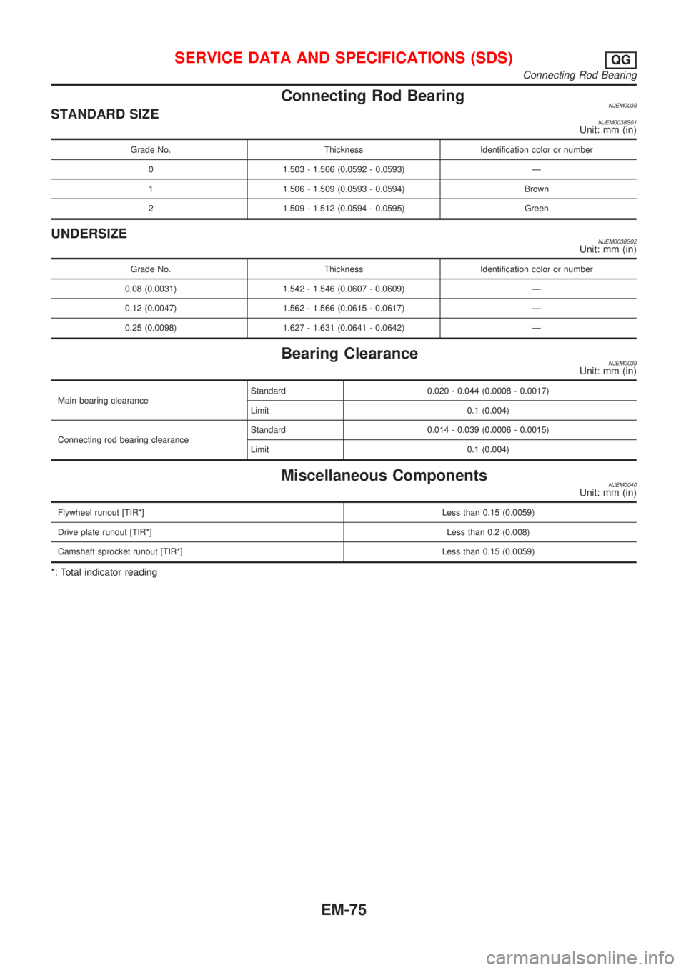
Connecting Rod BearingNJEM0038STANDARD SIZENJEM0038S01Unit: mm (in)
Grade No. Thickness Identification color or number
0 1.503 - 1.506 (0.0592 - 0.0593) Ð
1 1.506 - 1.509 (0.0593 - 0.0594) Brown
2 1.509 - 1.512 (0.0594 - 0.0595) Green
UNDERSIZENJEM0038S02Unit: mm (in)
Grade No. Thickness Identification color or number
0.08 (0.0031) 1.542 - 1.546 (0.0607 - 0.0609) Ð
0.12 (0.0047) 1.562 - 1.566 (0.0615 - 0.0617) Ð
0.25 (0.0098) 1.627 - 1.631 (0.0641 - 0.0642) Ð
Bearing ClearanceNJEM0039Unit: mm (in)
Main bearing clearanceStandard 0.020 - 0.044 (0.0008 - 0.0017)
Limit 0.1 (0.004)
Connecting rod bearing clearanceStandard 0.014 - 0.039 (0.0006 - 0.0015)
Limit 0.1 (0.004)
Miscellaneous ComponentsNJEM0040Unit: mm (in)
Flywheel runout [TIR*]Less than 0.15 (0.0059)
Drive plate runout [TIR*]Less than 0.2 (0.008)
Camshaft sprocket runout [TIR*] Less than 0.15 (0.0059)
*: Total indicator reading
SERVICE DATA AND SPECIFICATIONS (SDS)QG
Connecting Rod Bearing
EM-75
Page 243 of 2493

Camshaft and Camshaft Bearing=NJEM0080Unit: mm (in)
Standard Limit
Camshaft journal to bearing clearance 0.045 - 0.086 (0.0018 - 0.0034) 0.045 - 0.086 (0.0018 - 0.0034)
Inner diameter of camshaft bearingNo. 1
30.500 - 30.521 (1.2008 - 1.2016)
No. 2, 3, 4, 5
24.000 - 24.021 (0.9449 - 0.9457)Ð
Outer diameter of camshaft journalNo. 1
30.435 - 30.455 (1.1982 - 1.1990)
No. 2, 3, 4, 5
23.935 - 23.955 (0.9423 - 0.9431)Ð
Camshaft runout [TIR*] Ð 0.02 (0.0008)
Camshaft sprocket runout [TIR*] Less than 0.15 (0.0059) Ð
Camshaft end play 0.070 - 0.148 (0.0028 - 0.0058) 0.24 (0.0094)
*: Total indicator reading
EM671
Cam height ªAºIntake 39.505 - 39.695 (1.5553 - 1.5628)
Exhaust 39.905 - 40.095 (1.5711 - 1.5785)
Wear limit of cam height0.15 (0.0059)
Valve timing
EM120
Unit: degree
abcde f
Valve timing 224 212 2 30 ±2 46
SERVICE DATA AND SPECIFICATIONS (SDS)YD
Camshaft and Camshaft Bearing
EM-165
Page 246 of 2493
![NISSAN ALMERA N16 2001 Electronic Repair Manual Connecting RodNJEM0083Unit: mm (in)
Center distance157.5 (6.201)
Bend [per 100 (3.94)] Limit 0.12 (0.0047)
Torsion [per 100 (3.94)] Limit 0.12 (0.0047)
Connecting rod small end inner diameter 30.080 - NISSAN ALMERA N16 2001 Electronic Repair Manual Connecting RodNJEM0083Unit: mm (in)
Center distance157.5 (6.201)
Bend [per 100 (3.94)] Limit 0.12 (0.0047)
Torsion [per 100 (3.94)] Limit 0.12 (0.0047)
Connecting rod small end inner diameter 30.080 -](/manual-img/5/57351/w960_57351-245.png)
Connecting RodNJEM0083Unit: mm (in)
Center distance157.5 (6.201)
Bend [per 100 (3.94)] Limit 0.12 (0.0047)
Torsion [per 100 (3.94)] Limit 0.12 (0.0047)
Connecting rod small end inner diameter 30.080 - 31.000 (1.1842 - 1.2205)
Piston pin bushing inner diameter* 28.026 - 28.038 (1.1034 - 1.1039)
Connecting rod big end inner diameter 55.000 - 55.013 (2.1654 - 2.1659)
Side clearanceStandard 0.200 - 0.350 (0.0079 - 0.0138)
Limit 0.4 (0.016)
*: After installing in connecting rod
CrankshaftNJEM0084Unit: mm (in)
Main journal dia. ªDmº gradeGrade No. 0
Grade No. 1
Grade No. 262.967 - 62.975 (2.4790 - 2.4793)
62.959 - 62.967 (2.4787 - 2.4790)
62.951 - 62.959 (2.4784 - 2.4787)
Pin journal dia. ªDpºGrade No. 0 51.968 - 51.974 (2.0460 - 2.0462)
Grade No. 1 51.961 - 51.968 (2.0457 - 2.0460)
Grade No. 2 51.954 - 51.961 (2.0454 - 2.0457)
Center distance ªrº46.97 - 47.03 (1.8492 - 1.8516)
Out-of-round (X þ Y) Standard/Limit Less than 0.003 (0.0001)/Less than 0.005 (0.0002)
Taper (A þ B) Standard/Limit Less than 0.003 (0.0001)/Less than 0.005 (0.0002)
Runout [TIR*]Standard Less than 0.05 (0.0020)
Limit Less than 0.10 (0.0039)
Free end playStandard 0.10 - 0.25 (0.0039 - 0.0098)
Limit 0.30 (0.0118)
SEM645EM715
*: Total indicator reading
SERVICE DATA AND SPECIFICATIONS (SDS)YD
Connecting Rod
EM-168
Page 247 of 2493

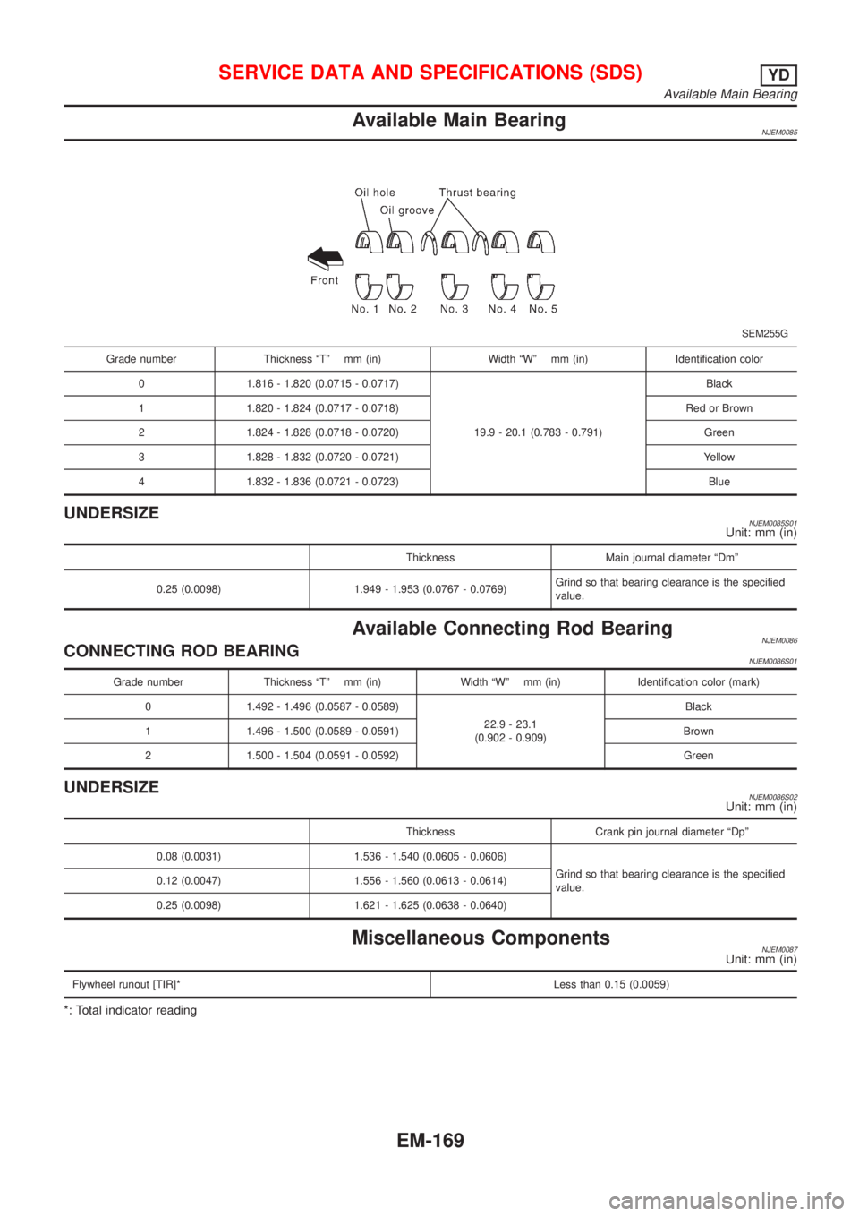
Available Main BearingNJEM0085
SEM255G
Grade number Thickness ªTº mm (in) Width ªWº mm (in) Identification color
0 1.816 - 1.820 (0.0715 - 0.0717)
19.9 - 20.1 (0.783 - 0.791)Black
1 1.820 - 1.824 (0.0717 - 0.0718) Red or Brown
2 1.824 - 1.828 (0.0718 - 0.0720) Green
3 1.828 - 1.832 (0.0720 - 0.0721) Yellow
4 1.832 - 1.836 (0.0721 - 0.0723) Blue
UNDERSIZENJEM0085S01Unit: mm (in)
Thickness Main journal diameter ªDmº
0.25 (0.0098) 1.949 - 1.953 (0.0767 - 0.0769)Grind so that bearing clearance is the specified
value.
Available Connecting Rod BearingNJEM0086CONNECTING ROD BEARINGNJEM0086S01
Grade number Thickness ªTº mm (in) Width ªWº mm (in) Identification color (mark)
0 1.492 - 1.496 (0.0587 - 0.0589)
22.9 - 23.1
(0.902 - 0.909)Black
1 1.496 - 1.500 (0.0589 - 0.0591) Brown
2 1.500 - 1.504 (0.0591 - 0.0592) Green
UNDERSIZENJEM0086S02Unit: mm (in)
Thickness Crank pin journal diameter ªDpº
0.08 (0.0031) 1.536 - 1.540 (0.0605 - 0.0606)
Grind so that bearing clearance is the specified
value. 0.12 (0.0047) 1.556 - 1.560 (0.0613 - 0.0614)
0.25 (0.0098) 1.621 - 1.625 (0.0638 - 0.0640)
Miscellaneous ComponentsNJEM0087Unit: mm (in)
Flywheel runout [TIR]*Less than 0.15 (0.0059)
*: Total indicator reading
SERVICE DATA AND SPECIFICATIONS (SDS)YD
Available Main Bearing
EM-169